2011 INFINITI QX56 weight
[x] Cancel search: weightPage 3672 of 5598

MA-2
FRONT DIFFERENTIAL GEAR OIL: R180A :
Draining ..................................................................
24
FRONT DIFFERENTIAL GEAR OIL: R180A : Re-
filling .......................................................................
25
REAR DIFFERENTIAL GEAR OIL: R230 ............. ...25
REAR DIFFERENTIAL GEAR OIL: R230 : Inspec-
tion ..........................................................................
25
REAR DIFFERENTIAL GEAR OIL: R230 : Drain-
ing ...........................................................................
25
REAR DIFFERENTIAL GEAR OIL: R230 : Refill-
ing ...........................................................................
26
WHEELS (BONDING WEIGHT TYPE) .....................26
WHEELS (BONDING WEIGHT TYPE) : Adjust-
ment ..................................................................... ...
26
BRAKE FLUID LEVEL AND LEAKS ........................27
BRAKE FLUID LEVEL AND LEAKS : Inspection ...28
BRAKE LINES AND CABLES ............................... ...28
BRAKE LINES AND CABLES : Inspection .............28
BRAKE FLUID ....................................................... ...28
BRAKE FLUID : Bleeding Brake System ................28
DISC BRAKE ......................................................... ...30
DISC BRAKE : Inspection ......................................30
DISC BRAKE : Front Disc Brake ............................31
DISC BRAKE : Rear Disc Brake .............................31
STEERING GEAR AND LINKAGE ........................ ...31
STEERING GEAR AND LINKAGE : Inspection ......31
POWER STEERING FLUID AND LINES ............... ...32
POWER STEERING FLUID AND LINES : Inspec-
tion ..........................................................................
32
AXLE AND SUSPENSION PARTS ...........................32
AXLE AND SUSPENSION PARTS : Inspection .. ...32
DRIVE SHAFT ........................................................ ...33
DRIVE SHAFT : Inspection .....................................33
BODY MAINTENANCE .....................................34
LOCKS, HINGES AND HOOD LATCH .................. ...34
LOCKS, HINGES AND HOOD LATCH : Lubricat-
ing ...........................................................................
34
SEAT BELT, BUCKLES, RETRACTORS, AN-
CHORS AND ADJUSTERS ................................... ...
34
SEAT BELT, BUCKLES, RETRACTORS, AN-
CHORS AND ADJUSTERS : Inspection .................
34
SERVICE DATA AND SPECIFICATIONS
(SDS) .......... ................................................
35
SERVICE DATA AND SPECIFICATIONS
(SDS) .............................................................. ...
35
DRIVE BELTS ........................................................ ...35
DRIVE BELTS : Drive Belts ....................................35
ENGINE COOLANT ............................................... ...35
ENGINE COOLANT :
Periodical Maintenance Specification ....................
35
ENGINE OIL ........................................................... ...35
ENGINE OIL : Periodical Maintenance Specifica-
tion ..........................................................................
35
SPARK PLUG ........................................................ ...35
SPARK PLUG : Spark Plug ....................................35
ROAD WHEEL ....................................................... ...35
ROAD WHEEL : Road Wheel .................................35
Revision: 2010 May2011 QX56
Page 3696 of 5598

MA-26
< PERIODIC MAINTENANCE >
CHASSIS MAINTENANCE
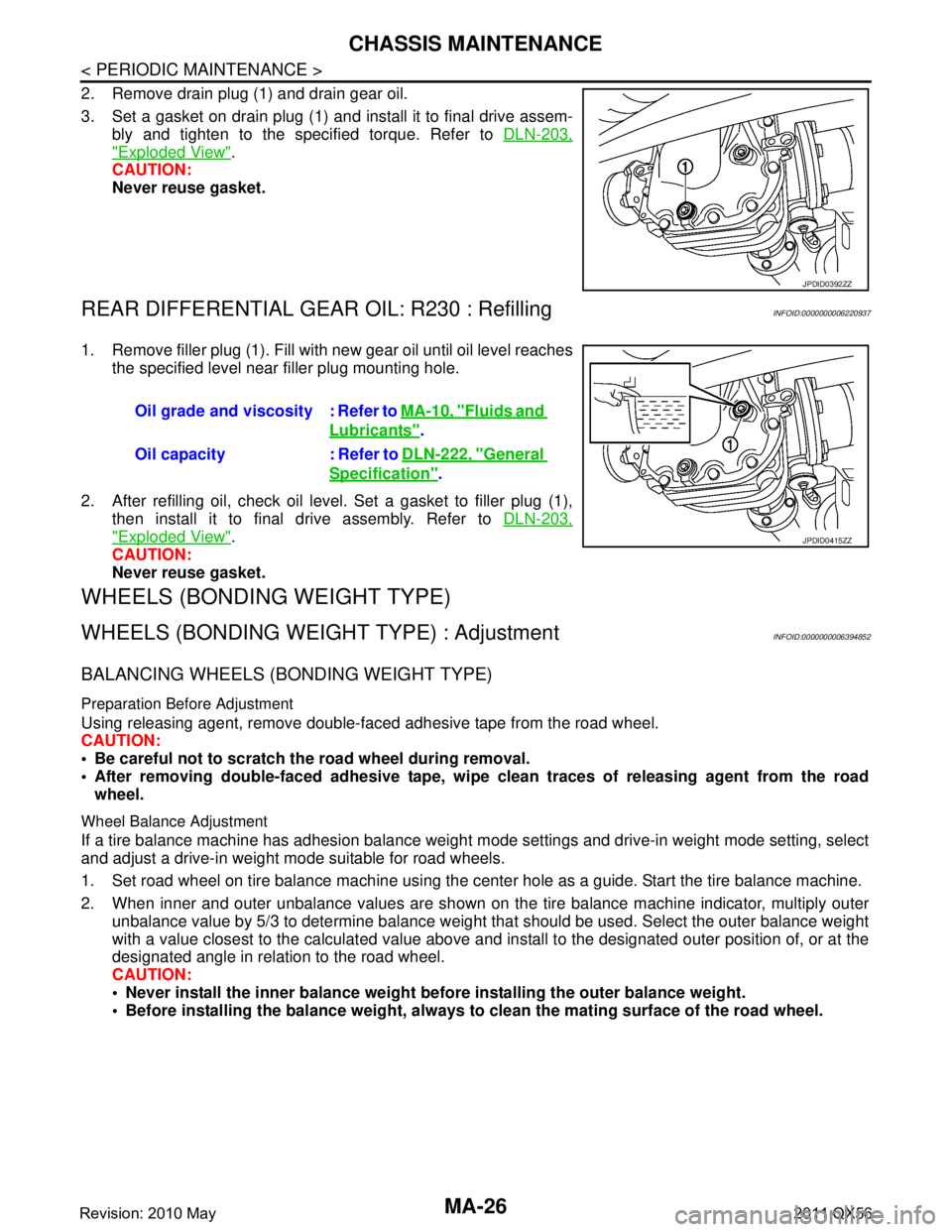
2. Remove drain plug (1) and drain gear oil.
3. Set a gasket on drain plug (1) and install it to final drive assem-bly and tighten to the specified torque. Refer to DLN-203,
"Exploded View".
CAUTION:
Never reuse gasket.
REAR DIFFERENTIAL GEAR OIL: R230 : RefillingINFOID:0000000006220937
1. Remove filler plug (1). Fill with new gear oil until oil level reaches
the specified level near filler plug mounting hole.
2. After refilling oil, check oil level. Set a gasket to filler plug (1), then install it to final drive assembly. Refer to DLN-203,
"Exploded View".
CAUTION:
Never reuse gasket.
WHEELS (BONDING WEIGHT TYPE)
WHEELS (BONDING WEIG HT TYPE) : AdjustmentINFOID:0000000006394852
BALANCING WHEELS (BONDING WEIGHT TYPE)
Preparation Before Adjustment
Using releasing agent, remove double-faced adhesive tape from the road wheel.
CAUTION:
Be careful not to scratch th e road wheel during removal.
After removing double-faced adhesive tape, wi pe clean traces of releasing agent from the road
wheel.
Wheel Balance Adjustment
If a tire balance machine has adhesion balance weight m ode settings and drive-in weight mode setting, select
and adjust a drive-in weight mode suitable for road wheels.
1. Set road wheel on tire balance machine using the center hole as a guide. Start the tire balance machine.
2. When inner and outer unbalance values are shown on the tire balance machine indicator, multiply outer unbalance value by 5/3 to determine balance weight t hat should be used. Select the outer balance weight
with a value closest to the calculated value above and in stall to the designated outer position of, or at the
designated angle in relation to the road wheel.
CAUTION:
Never install the inner balance weight be fore installing the outer balance weight.
Before installing the balance weight, always to clean the mating surface of the road wheel.
JPDID0392ZZ
Oil grade and viscosity : Refer to MA-10, "Fluids and
Lubricants".
Oil capacity : Refer to DLN-222, "
General
Specification".
JPDID0415ZZ
Revision: 2010 May2011 QX56
Page 3697 of 5598

CHASSIS MAINTENANCEMA-27
< PERIODIC MAINTENANCE >
C
DE
F
G H
I
J
K L
M B
MA
N
O A
a. Indicated unbalance value
× 5/3 = balance weight to be installed
Calculation example:
23 g (0.81 oz) × 5/3 = 38.33 g (1.35 oz) ⇒ 37.5 g (1.32 oz) bal-
ance weight (closer to calculated balance weight value)
NOTE:
Note that balance weight value must be closer to the calculated
balance weight value.
Example:
36.2 ⇒ 35 g (1.23 oz)
36.3 ⇒ 37.5 g (1.32 oz)
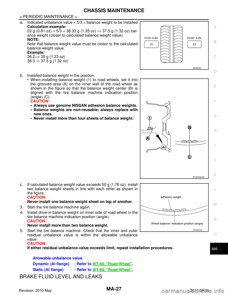
b. Installed balance weight in the position. When installing balance weight (1) to road wheels, set it into
the grooved area (A) on the inner wall of the road wheel as
shown in the figure so that the balance weight center (B) is
aligned with the tire balance machine indication position
(angle) (C).
CAUTION:
Always use genuine NISSAN ad hesion balance weights.
Balance weights are non-re usable; always replace with
new ones.
Never install more than four sheets of balance weight.
c. If calculated balance weight value exceeds 50 g (1.76 oz), install two balance weight sheets in line with each other as shown in
the figure.
CAUTION:
Never install one balance weight sheet on top of another.
3. Start the tire balance machine again.
4. Install drive-in balance weight on inner side of road wheel in the tire balance machine indication position (angle).
CAUTION:
Never install more than two balance weight.
5. Start the tire balance machine. Check that the inner and outer residual unbalance value is within the allowable unbalance
value.
CAUTION:
If either residual unbalan ce value exceeds limit, repeat installation procedures.
BRAKE FLUID LEVEL AND LEAKS
SMA054D
JPEIC0040ZZ
Allowable unbalance value
Dynamic (At flange) : Refer to WT-69, "
Road Wheel".
Static (At flange) : Refer to WT-69, "
Road Wheel".
PEIA0033E
Revision: 2010 May2011 QX56
Page 5095 of 5598
![INFINITI QX56 2011 Factory Service Manual
PRECAUTIONSTM-7
< PRECAUTION > [7AT: RE7R01B]
C
EF
G H
I
J
K L
M A
B
TM
N
O P
Disassembly should be done in a clean work area.
Use lint-free paper or towels for wiping parts clean. Common shop r INFINITI QX56 2011 Factory Service Manual
PRECAUTIONSTM-7
< PRECAUTION > [7AT: RE7R01B]
C
EF
G H
I
J
K L
M A
B
TM
N
O P
Disassembly should be done in a clean work area.
Use lint-free paper or towels for wiping parts clean. Common shop r](/manual-img/42/57033/w960_57033-5094.png)
PRECAUTIONSTM-7
< PRECAUTION > [7AT: RE7R01B]
C
EF
G H
I
J
K L
M A
B
TM
N
O P
Disassembly should be done in a clean work area.
Use lint-free paper or towels for wiping parts clean. Common shop rags can leave fibers that could interfere
with the operation of the transmission.
Place disassembled parts in order for easier and proper assembly.
All parts should be carefully cleaned with a general purpose, non-flammable solvent before inspection or
reassembly.
Gaskets, seals and O-rings should be repl aced any time the A/T is disassembled.
It is very important to perform func tional tests whenever they are indicated.
The valve body contains precision parts and requires extreme care when parts are removed and serviced.
Place disassembled valve body parts in order for easier and proper assembly. Care will also prevent springs
and small parts from becoming scattered or lost.
Properly installed valves, sleeves, plugs, etc. will slide along bores in valve body under their own weight.
Before assembly, apply a coat of recommended ATF to all parts. Apply petroleum jelly to protect O-rings and
seals, or hold bearings and washers in place during assembly. Never use grease.
Extreme care should be taken to avoid damage to O-rings, seals and gaskets when assembling.
When the A/T drain plug is removed, only some of the ATF is drained. Old ATF will remain in torque con- verter and ATF cooling system.
Always follow the procedures under “Changing” when changing ATF. Refer to TM-94, "
Changing".
Occasionally, the parking gear may be locked with the to rque insufficiently released, when stopping the vehi-
cle by shifting the selector lever from “D” or “R” to “P” position with the brake pedal depressed.
In this case, the shock with a thud caused by the abrupt release of torque may occur when shifting the selec-
tor lever from “P” posit ion to other positions.
However, this symptom is not a malfunction which results in the damage of parts.
Service Notice or PrecautionINFOID:0000000006274263
ATF COOLER SERVICE
If ATF contains frictional material (clutches, bands, etc. ), or if an A/T is repaired, overhauled, or replaced,
inspect and clean the A/T fluid cooler mounted in the radiat or or replace the radiator. Flush cooler lines using
cleaning solvent and compressed air after repair. For A/T fluid cooler cleaning procedure, refer to TM-97,
"Cleaning". For radiator replacement, refer to CO-13, "Exploded View".
Revision: 2010 May2011 QX56
Page 5454 of 5598

WT-4
< PRECAUTION >
PRECAUTIONS
5. When the repair work is completed, re-connect both battery cables. With the brake pedal released, turn
the push-button ignition switch from ACC position to ON position, then to LOCK position. (The steering
wheel will lock when the push-button igniti on switch is turned to LOCK position.)
6. Perform self-diagnosis check of all control units using CONSULT-III.
Service Notice or Precautions for TPMSINFOID:0000000006225485
Low tire pressure warning lamp blinks for 1min, then turns ON when occurring any malfunction except low tire pressure. Erase the self-diagnosis memories for low tire pressure warning control unit, or register the ID
to turn low tire pressure warning lamp OFF. For ID registration, refer to WT-29, "
Work Procedure".
ID registration is required when replacing or rotating wheel s, replacing transmitter or low tire pressure warn-
ing control unit. Refer to WT-29, "
Work Procedure".
Replace grommet seal, valve core and cap of transmitter in TPMS, when replacing each tire by reaching the
wear limit. Refer to WT-66, "
Exploded View".
For tire inflation indicator function, refer to the following.
- When inflating the tires, park the vehicle in the safe area and ensure the safety of the working area.
- Read and understand the tire inflation indicator function prior to use.
- Inflate the tires one at a time.
- If there is no response for approximately 15 seconds or mo re after inflating the tires, cancel the use of the
tire inflation indicator function or move the vehicle approximately 1 m (3.2 ft) backward or forward to try
again. The air filler pressure may be weak or out of service area.
- Despite the high-precision TPMS pressure sensor, an i ndicated value may differ from that of the pressure
gauge.
- Air pressure is measured rather high due to the rise in tire air temperature after driving.
- If TPMS is malfunctioning, the tire inflation indicator is unusable.
Service Notice or Precautions for Road WheelINFOID:0000000006225486
Genuine NISSAN aluminum wheel is designed for each type of vehicle. Use it on the specified vehicle only.
Use Genuine NISSAN parts for the wheel nuts.
Always use them after adjusting the wheel balance. For the balance weights, use Genuine NISSAN alumi-
num wheel weights.
Use caution when handling the aluminum wheels, because they can be easily scratched. When removing
dirt, do not use any abrasives, a wire brush, or other it ems that may scratch the coating. Use a neutral deter-
gent if a detergent is needed.
After driving on roads scattered with anti-ici ng salts, wash off the wheels completely.
When installing road wheels onto the vehicle, always wipe of f any dirt or foreign substances to prevent them
from being trapped between the contact surfaces of wheel.
Never apply oil to nut and bolt threads.
Revision: 2010 May2011 QX56
Page 5512 of 5598

WT-62
< PERIODIC MAINTENANCE >
ROAD WHEEL
PERIODIC MAINTENANCE
ROAD WHEEL
AdjustmentINFOID:0000000006225545
BALANCING WHEELS (BONDING WEIGHT TYPE)
Preparation Before Adjustment
Using releasing agent, remove double-faced adhesive tape from the road wheel.
CAUTION:
Be careful not to scratch the road wheel during removal.
After removing double-faced adhesive tape, wi pe clean traces of releasing agent from the road
wheel.
Wheel Balance Adjustment
If a tire balance machine has adhesion balance weight m ode settings and drive-in weight mode setting, select
and adjust a drive-in weight mode suitable for road wheels.
1. Set road wheel on tire balance machine using the center hole as a guide. Start the tire balance machine.
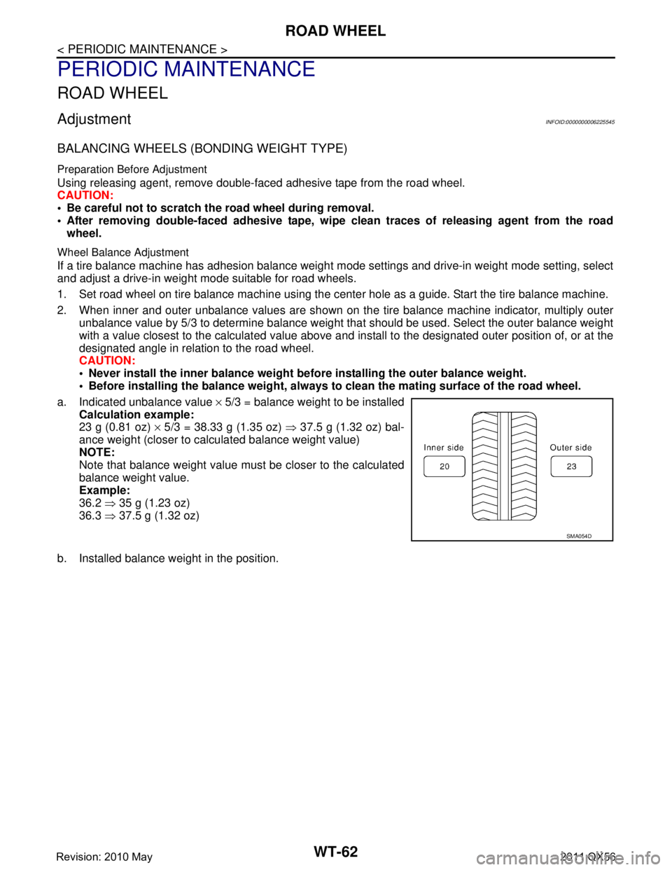
2. When inner and outer unbalance values are shown on the tire balance machine indicator, multiply outer unbalance value by 5/3 to determine balance weight t hat should be used. Select the outer balance weight
with a value closest to the calculated value above and in stall to the designated outer position of, or at the
designated angle in relation to the road wheel.
CAUTION:
Never install the inner balance weight be fore installing the outer balance weight.
Before installing the balance weight, always to clean the mating surface of the road wheel.
a. Indicated unbalance value × 5/3 = balance weight to be installed
Calculation example:
23 g (0.81 oz) × 5/3 = 38.33 g (1.35 oz) ⇒ 37.5 g (1.32 oz) bal-
ance weight (closer to calculated balance weight value)
NOTE:
Note that balance weight value must be closer to the calculated
balance weight value.
Example:
36.2 ⇒ 35 g (1.23 oz)
36.3 ⇒ 37.5 g (1.32 oz)
b. Installed balance weight in the position.
SMA054D
Revision: 2010 May2011 QX56
Page 5513 of 5598

ROAD WHEELWT-63
< PERIODIC MAINTENANCE >
C
DF
G H
I
J
K L
M A
B
WT
N
O P
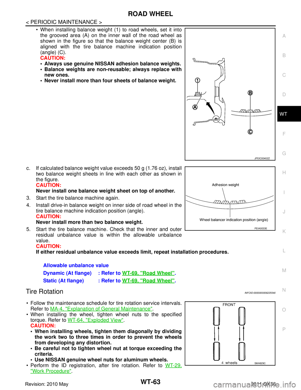
When installing balance weight (1) to road wheels, set it into the grooved area (A) on the inner wall of the road wheel as
shown in the figure so that the balance weight center (B) is
aligned with the tire balance machine indication position
(angle) (C).
CAUTION:
Always use genuine NISSAN ad hesion balance weights.
Balance weights are non-re usable; always replace with
new ones.
Never install more than four sheets of balance weight.
c. If calculated balance weight value exceeds 50 g (1.76 oz), install two balance weight sheets in line with each other as shown in
the figure.
CAUTION:
Never install one balance weight sheet on top of another.
3. Start the tire balance machine again.
4. Install drive-in balance weight on inner side of road wheel in the tire balance machine indication position (angle).
CAUTION:
Never install more than two balance weight.
5. Start the tire balance machine. Check that the inner and outer residual unbalance value is within the allowable unbalance
value.
CAUTION:
If either residual unbalan ce value exceeds limit, repeat installation procedures.
Tire RotationINFOID:0000000006225546
Follow the maintenance schedule for tire rotation service intervals.
Refer to MA-4, "
Explanation of General Maintenance".
When installing the wheel, tighten wheel nuts to the specified torque. Refer to WT-64, "
Exploded View".
CAUTION:
When installing wheels, tighte n them diagonally by dividing
the work two to three times in order to prevent the wheels
from developing any distortion.
Be careful not to tighten wh eel nut at torque exceeding the
criteria.
Use NISSAN genuine wheel nuts for aluminum wheels.
Perform the ID registration, after tire rotation. Refer to WT-29,
"Work Procedure".
JPEIC0040ZZ
Allowable unbalance value
Dynamic (At flange) : Refer to WT-69, "
Road Wheel".
Static (At flange) : Refer to WT-69, "
Road Wheel".
PEIA0033E
SMA829C
Revision: 2010 May2011 QX56