2011 INFINITI QX56 weight
[x] Cancel search: weightPage 2670 of 5598
EM-108
< UNIT DISASSEMBLY AND ASSEMBLY >
CYLINDER BLOCK
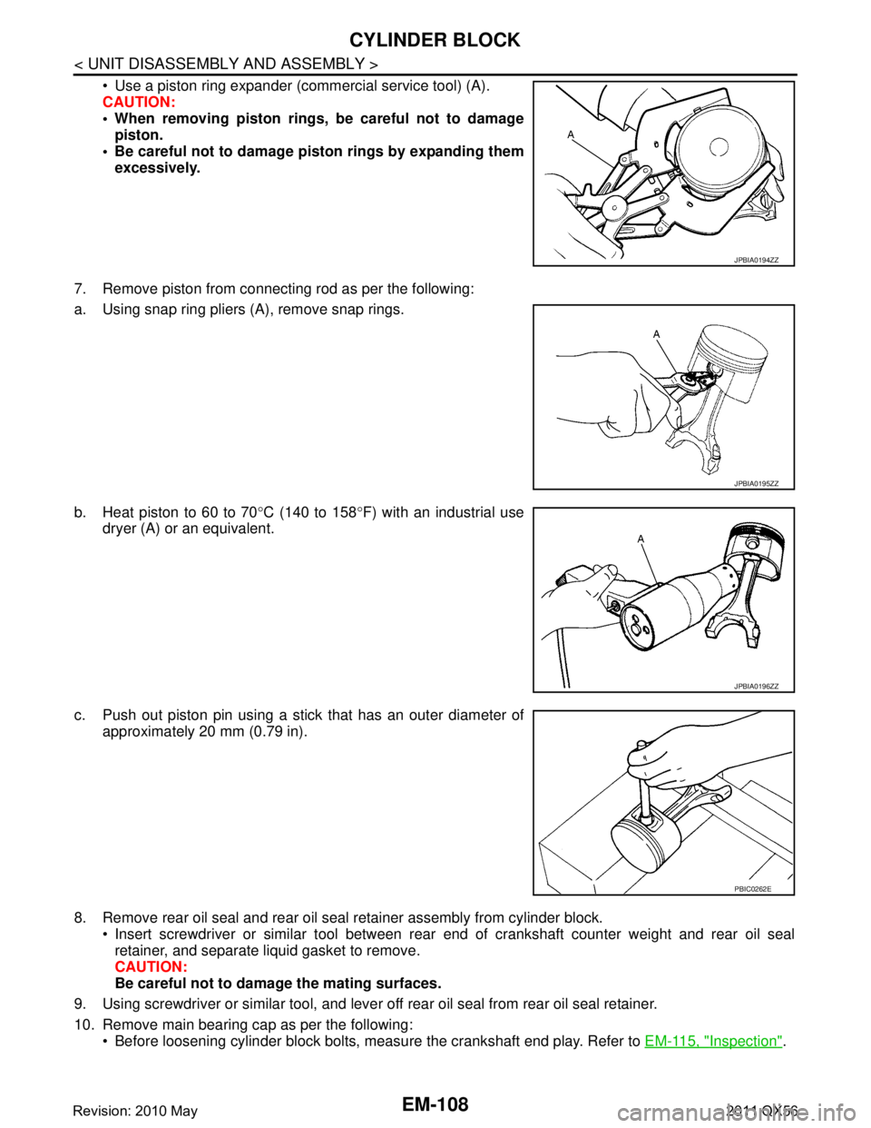
Use a piston ring expander (commercial service tool) (A).
CAUTION:
When removing piston rings, be careful not to damagepiston.
Be careful not to damage piston rings by expanding them
excessively.
7. Remove piston from connecting rod as per the following:
a. Using snap ring pliers (A), remove snap rings.
b. Heat piston to 60 to 70 °C (140 to 158 °F) with an industrial use
dryer (A) or an equivalent.
c. Push out piston pin using a stick that has an outer diameter of approximately 20 mm (0.79 in).
8. Remove rear oil seal and rear oil seal retainer assembly from cylinder block. Insert screwdriver or similar tool between rear end of crankshaft counter weight and rear oil sealretainer, and separate liquid gasket to remove.
CAUTION:
Be careful not to damage the mating surfaces.
9. Using screwdriver or similar tool, and lever off rear oil seal from rear oil seal retainer.
10. Remove main bearing cap as per the following: Before loosening cylinder block bolts, measure the crankshaft end play. Refer to EM-115, "
Inspection".
JPBIA0194ZZ
JPBIA0195ZZ
JPBIA0196ZZ
PBIC0262E
Revision: 2010 May2011 QX56
Page 2676 of 5598
EM-114
< UNIT DISASSEMBLY AND ASSEMBLY >
CYLINDER BLOCK
Before installing connecting rod bearings, apply engine oil to the bearing surface (inside). Do not applyengine oil to the back surface, but thoroughly clean it.
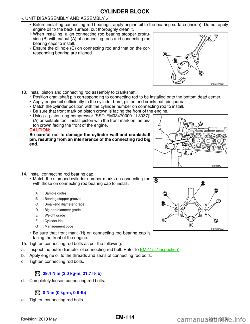
When installing, align connecting rod bearing stopper protru-
sion (B) with cutout (A) of connecting rods and connecting rod
bearing caps to install.
Ensure the oil hole (C) on connecting rod and that on the cor-
responding bearing are aligned.
13. Install piston and connecting rod assembly to crankshaft. Position crankshaft pin corresponding to connecting rod to be installed onto the bottom dead center.
Apply engine oil sufficiently to the cylinder bore, piston and crankshaft pin journal.
Match the cylinder position with the cyli nder number on connecting rod to install.
Be sure that front mark on piston cr own is facing the front of the engine.
Using a piston ring compressor [SST: EM03470000 (J-8037)]
(A) or suitable tool, install piston with the front mark on the pis-
ton crown facing the front of the engine.
CAUTION:
Be careful not to damage the cylinder wall and crankshaft
pin, resulting from an interf erence of the connecting rod big
end.
14. Install connecting rod bearing cap. Match the stamped cylinder number marks on connecting rodwith those on connecting rod bearing cap to install.
Be sure that front mark (H) on connecting rod bearing cap is facing the front of the engine.
15. Tighten connecting rod bolts as per the following:
a. Inspect the outer diameter of connecting rod bolt. Refer to EM-115, "
Inspection".
b. Apply engine oil to the threads and seats of connecting rod bolts.
c. Tighten connecting rod bolts.
d. Completely loosen connecting rod bolts.
e. Tighten connecting rod bolts.
JPBIA2272ZZ
PBIC3244J
A: Sample codes
B : Bearing stopper groove
C : Small-end diameter grade
D : Big-end diameter grade
E : Weight grade
F : Cylinder No.
G : Management code
: 29.4 N·m (3.0 kg-m, 21.7 ft-lb)
: 0 N·m (0 kg-m, 0 ft-lb)
JPBIA2273ZZ
Revision: 2010 May2011 QX56
Page 2688 of 5598
EM-126
< UNIT DISASSEMBLY AND ASSEMBLY >
HOW TO SELECT PISTON AND BEARING
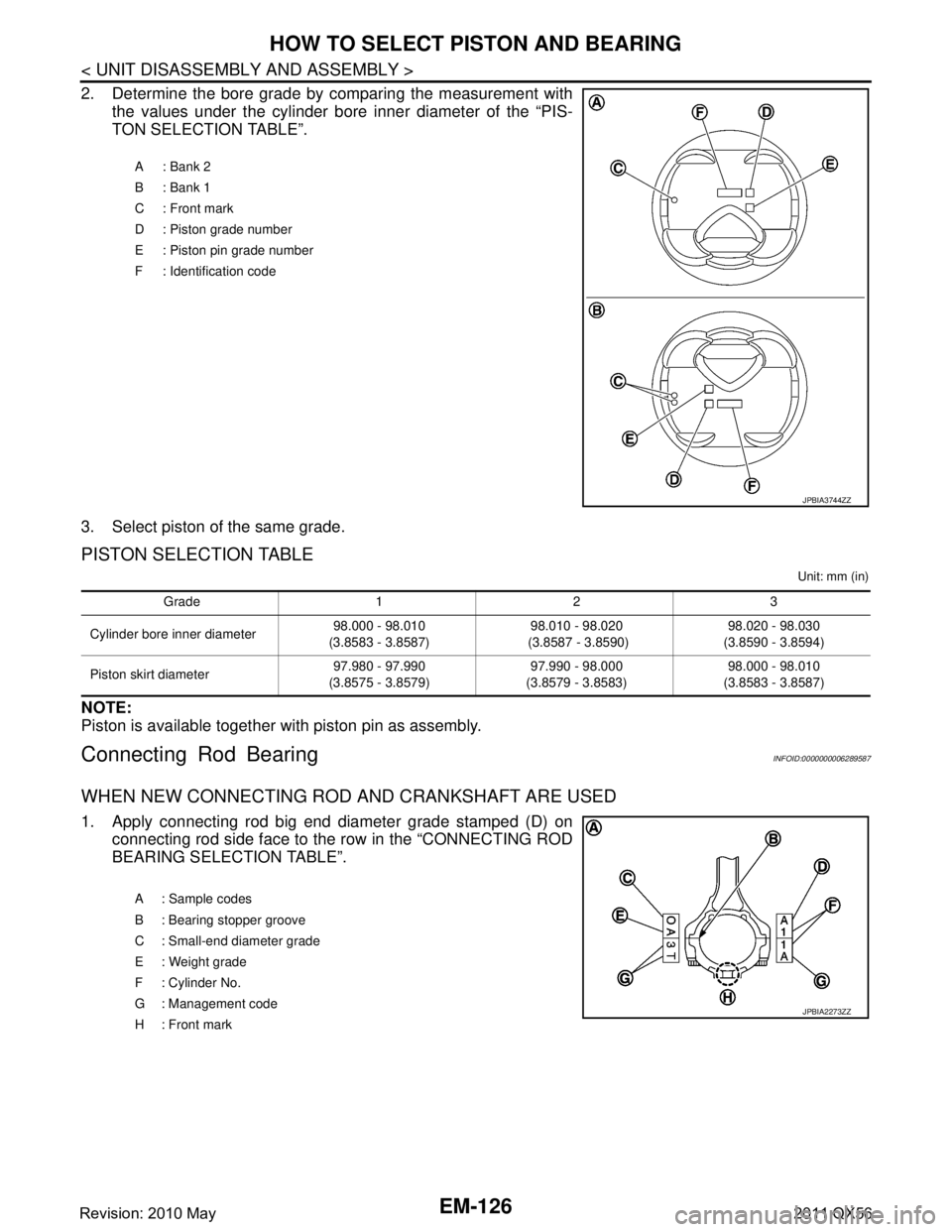
2. Determine the bore grade by comparing the measurement withthe values under the cylinder bore inner diameter of the “PIS-
TON SELECTION TABLE”.
3. Select piston of the same grade.
PISTON SELECTION TABLE
Unit: mm (in)
NOTE:
Piston is available together with piston pin as assembly.
Connecting Rod BearingINFOID:0000000006289587
WHEN NEW CONNECTING ROD AND CRANKSHAFT ARE USED
1. Apply connecting rod big end diameter grade stamped (D) on connecting rod side face to the row in the “CONNECTING ROD
BEARING SELECTION TABLE”.
A: Bank 2
B: Bank 1
C : Front mark
D : Piston grade number
E : Piston pin grade number
F : Identification code
JPBIA3744ZZ
Grade 1 2 3
Cylinder bore inner diameter 98.000 - 98.010
(3.8583 - 3.8587) 98.010 - 98.020
(3.8587 - 3.8590) 98.020 - 98.030
(3.8590 - 3.8594)
Piston skirt diameter 97.980 - 97.990
(3.8575 - 3.8579) 97.990 - 98.000
(3.8579 - 3.8583) 98.000 - 98.010
(3.8583 - 3.8587)
A : Sample codes
B : Bearing stopper groove
C : Small-end diameter grade
E : Weight grade
F : Cylinder No.
G : Management code
H: Front mark
JPBIA2273ZZ
Revision: 2010 May2011 QX56
Page 2992 of 5598
GI-28
< PRECAUTION >
PRECAUTIONS
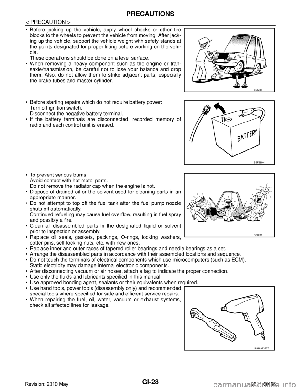
Before jacking up the vehicle, apply wheel chocks or other tireblocks to the wheels to prevent t he vehicle from moving. After jack-
ing up the vehicle, support the vehicle weight with safety stands at
the points designated for proper lifting before working on the vehi-
cle.
These operations should be done on a level surface.
When removing a heavy component such as the engine or tran- saxle/transmission, be careful not to lose your balance and drop
them. Also, do not allow them to strike adjacent parts, especially
the brake tubes and master cylinder.
Before starting repairs which do not require battery power: Turn off ignition switch.
Disconnect the negative battery terminal.
If the battery terminals are disconnected, recorded memory of
radio and each control unit is erased.
To prevent serious burns: Avoid contact with hot metal parts.
Do not remove the radiator cap when the engine is hot.
Dispose of drained oil or the solvent used for cleaning parts in an appropriate manner.
Do not attempt to top off the fuel tank after the fuel pump nozzle
shuts off automatically.
Continued refueling may cause fuel overflow, resulting in fuel spray
and possibly a fire.
Clean all disassembled parts in the designated liquid or solvent prior to inspection or assembly.
Replace oil seals, gaskets, packings, O-rings, locking washers,
cotter pins, self-locking nuts, etc. with new ones.
Replace inner and outer races of tapered roller bearings and needle bearings as a set.
Arrange the disassembled parts in accordance with their assembled locations and sequence.
Do not touch the terminals of electrical com ponents which use microcomputers (such as ECM).
Static electricity may damage internal electronic components.
After disconnecting vacuum or air hoses, atta ch a tag to indicate the proper connection.
Use only the fluids and lubricants specified in this manual.
Use approved bonding agent, sealants or their equivalents when required.
Use hand tools, power tools (disassembly only) and recommended special tools where specified for safe and efficient service repairs.
When repairing the fuel, oil, water, vacuum or exhaust systems, check all affected lines for leakage.
SGI231
SEF289H
SGI233
JPAIA0335ZZ
Revision: 2010 May2011 QX56
Page 3064 of 5598
HA-8
< PRECAUTION >
PRECAUTIONS
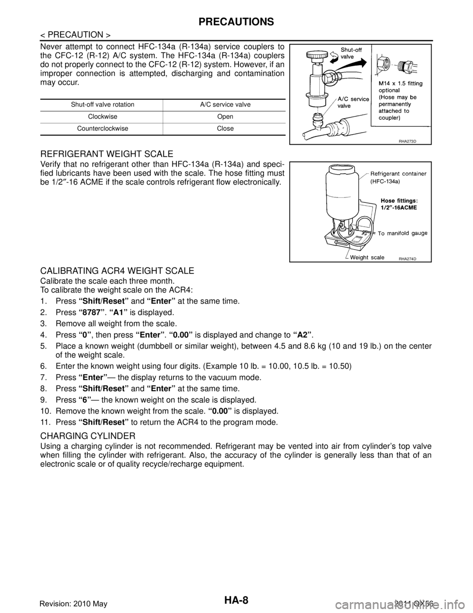
Never attempt to connect HFC-134a (R-134a) service couplers to
the CFC-12 (R-12) A/C system. The HFC-134a (R-134a) couplers
do not properly connect to the CFC-12 (R-12) system. However, if an
improper connection is attempted, discharging and contamination
may occur.
REFRIGERANT WEIGHT SCALE
Verify that no refrigerant other than HFC-134a (R-134a) and speci-
fied lubricants have been used with the scale. The hose fitting must
be 1/2″-16 ACME if the scale controls refrigerant flow electronically.
CALIBRATING ACR4 WEIGHT SCALE
Calibrate the scale each three month.
To calibrate the weight scale on the ACR4:
1. Press “Shift/Reset” and “Enter” at the same time.
2. Press “8787”. “A1” is displayed.
3. Remove all weight from the scale.
4. Press “0”, then press “Enter”. “0.00” is displayed and change to “A2”.
5. Place a known weight (dumbbell or similar weight ), between 4.5 and 8.6 kg (10 and 19 lb.) on the center
of the weight scale.
6. Enter the known weight using four digi ts. (Example 10 lb. = 10.00, 10.5 lb. = 10.50)
7. Press “Enter”— the display returns to the vacuum mode.
8. Press “Shift/Reset” and “Enter” at the same time.
9. Press “6”— the known weight on the scale is displayed.
10. Remove the known weight from the scale. “0.00” is displayed.
11. Press “Shift/Reset” to return the ACR4 to the program mode.
CHARGING CYLINDER
Using a charging cylinder is not recommended. Refrigerant may be vented into air from cylinder’s top valve
when filling the cylinder with refrigerant. Also, the accu racy of the cylinder is generally less than that of an
electronic scale or of quality recycle/recharge equipment.
Shut-off valve rotati on A/C service valve
Clockwise Open
Counterclockwise Close
RHA273D
RHA274D
Revision: 2010 May2011 QX56
Page 3067 of 5598
PREPARATIONHA-11
< PREPARATION >
C
DE
F
G H
J
K L
M A
B
HA
N
O P
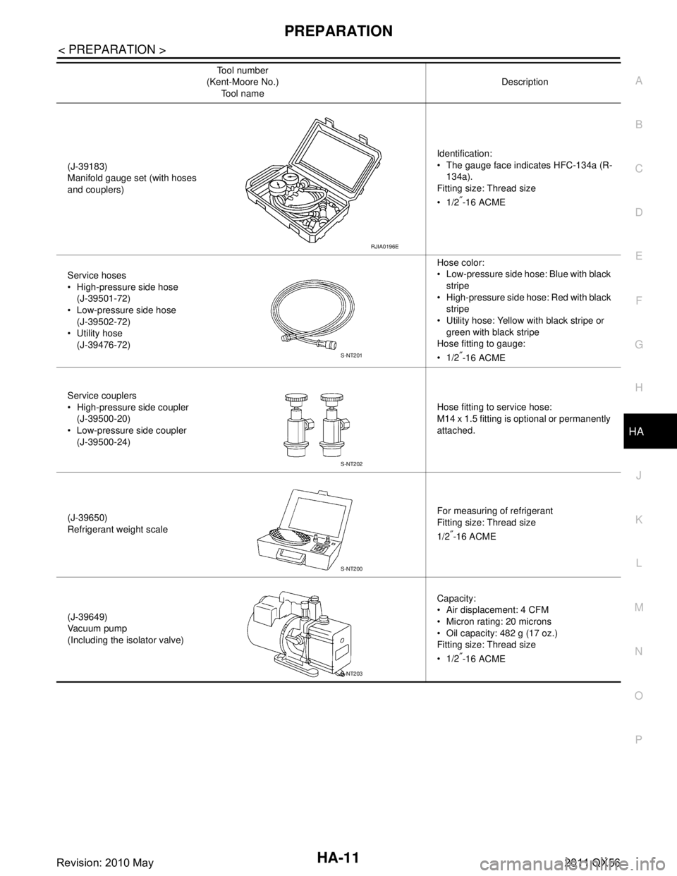
(J-39183)
Manifold gauge set (with hoses
and couplers) Identification:
The gauge face indicates HFC-134a (R-
134a).
Fitting size: Thread size
1/2
″-16 ACME
Service hoses
High-pressure side hose (J-39501-72)
Low-pressure side hose
(J-39502-72)
Utility hose (J-39476-72) Hose color:
Low-pressure side hose: Blue with black
stripe
High-pressure side hose: Red with black stripe
Utility hose: Yellow with black stripe or
green with black stripe
Hose fitting to gauge:
1/2
″-16 ACME
Service couplers
High-pressure side coupler (J-39500-20)
Low-pressure side coupler (J-39500-24) Hose fitting to service hose:
M14 x 1.5 fitting is optional or permanently
attached.
(J-39650)
Refrigerant weight scale For measuring of refrigerant
Fitting size: Thread size
1/2
″-16 ACME
(J-39649)
Va c u u m p u m p
(Including the isolator valve) Capacity:
Air displacement: 4 CFM
Micron rating: 20 microns
Oil capacity: 482 g (17 oz.)
Fitting size: Thread size
1/2
″-16 ACME
Tool number
(Kent-Moore No.)
Tool name Description
RJIA0196E
S-NT201
S-NT202
S-NT200
S-NT203
Revision: 2010 May2011 QX56
Page 3074 of 5598
HA-18
< BASIC INSPECTION >
REFRIGERANT
REFRIGERANT
DescriptionINFOID:0000000006276149
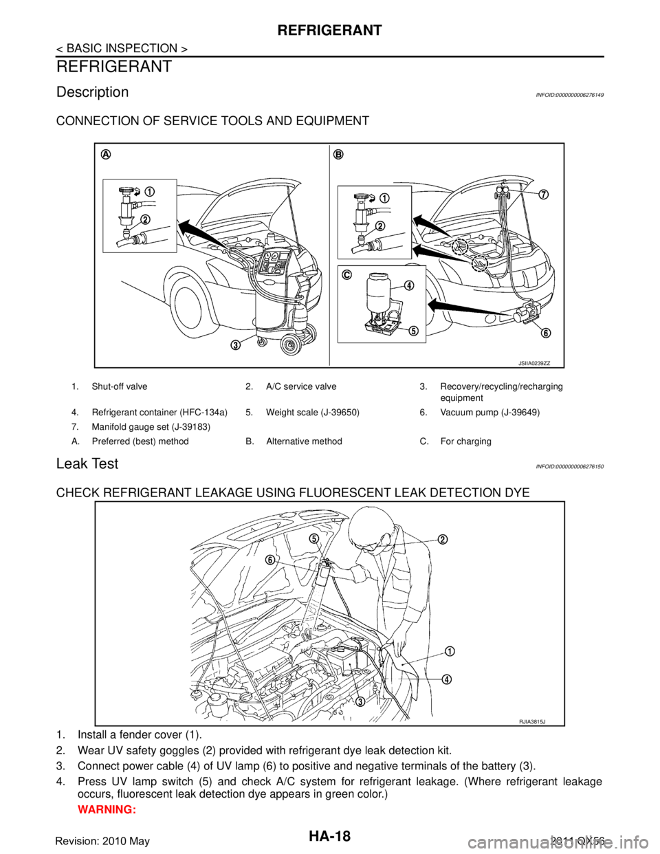
CONNECTION OF SERVICE TOOLS AND EQUIPMENT
Leak TestINFOID:0000000006276150
CHECK REFRIGERANT LEAKAGE USING FLUORESCENT LEAK DETECTION DYE
1. Install a fender cover (1).
2. Wear UV safety goggles (2) provided with refrigerant dye leak detection kit.
3. Connect power cable (4) of UV lamp (6) to positive and negative terminals of the battery (3).
4. Press UV lamp switch (5) and check A/C system for refrigerant leakage. (Where refrigerant leakage
occurs, fluorescent leak detec tion dye appears in green color.)
WARNING:
1. Shut-off valve 2. A/C service valve 3. Recovery/recycling/recharging equipment
4. Refrigerant container (HFC-134a) 5. Weight scale (J-39650) 6. Vacuum pump (J-39649)
7. Manifold gauge set (J-39183)
A. Preferred (best) method B. Alternative method C. For charging
JSIIA0239ZZ
RJIA3815J
Revision: 2010 May2011 QX56
Page 3669 of 5598
LU-16
< REMOVAL AND INSTALLATION >
OIL PUMP
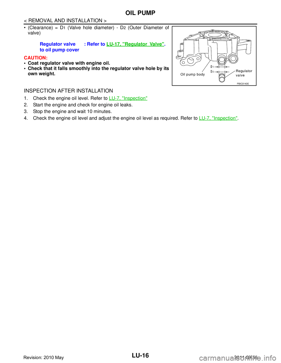
(Clearance) = D1 (Valve hole diameter) - D2 (Outer Diameter of
valve)
CAUTION:
Coat regulator valve with engine oil.
Check that it falls smoothly into the regulator valve hole by its
own weight.
INSPECTION AFTER INSTALLATION
1. Check the engine oil level. Refer to LU-7, "Inspection"
2. Start the engine and check for engine oil leaks.
3. Stop the engine and wait 10 minutes.
4. Check the engine oil level and adjust the engine oil level as required. Refer to LU-7, "
Inspection".
Regulator valve
to oil pump cover
: Refer to
LU-17, "
RegulatorVa l v e".
PBIC0143E
Revision: 2010 May2011 QX56