Page 3278 of 5598

SYSTEMINL-11
< SYSTEM DESCRIPTION >
C
DE
F
G H
I
J
K
M A
B
INL
N
O P
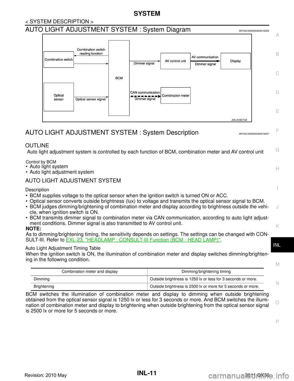
AUTO LIGHT ADJUSTMENT SYSTEM : System DiagramINFOID:0000000006216056
AUTO LIGHT ADJUSTMENT SYSTEM : System DescriptionINFOID:0000000006216057
OUTLINE
Auto light adjustment system is controlled by each f unction of BCM, combination meter and AV control unit
Control by BCM Auto light system
Auto light adjustment system
AUTO LIGHT ADJUSTMENT SYSTEM
Description
BCM supplies voltage to the optical sensor when the ignition switch is turned ON or ACC.
Optical sensor converts outside brightness (lux) to voltage and transmits the optical sensor signal to BCM.
BCM judges dimming/brightening of combination meter and display according to brightness outside the vehi- cle, when ignition switch is ON.
BCM transmits dimmer signal to combination meter via CAN communication, according to auto light adjust- ment conditions. Dimmer signal is also transmitted to AV control unit.
NOTE:
As to dimming/brightening timing, the sensitivity depends on settings. The settings can be changed with CON-
SULT-III. Refer to EXL-23, "
HEADLAMP : CONSULT-III F unction (BCM - HEAD LAMP)".
Auto Light Adjustment Timing Table
When the ignition switch is ON, the illumination of co mbination meter and display switches dimming/brighten-
ing in the following condition.
BCM switches the illumination of combination me ter and display to dimming when outside brightening
obtained from the optical sensor signal is 1250 lx or le ss for 3 seconds or more. And BCM switches the illumi-
nation of combination meter and display to brightening when outside brightening from the optical sensor signal
is 2500 lx or more for 5 seconds or more.
JMLIA0967GB
Combination meter and display Dimming/brightening timing
Dimming Outside brightness is 1250 lx or less for 3 seconds or more.
Brightening Outside brightness is 2500 lx or more for 5 seconds or more.
Revision: 2010 May2011 QX56
Page 3285 of 5598
INL-18
< WIRING DIAGRAM >
INTERIOR ROOM LAMP CONTROL SYSTEM
WIRING DIAGRAM
INTERIOR ROOM LAMP CONTROL SYSTEM
Wiring DiagramINFOID:0000000006216062
JCLWM5455GB
Revision: 2010 May2011 QX56
Page 3286 of 5598
INTERIOR ROOM LAMP CONTROL SYSTEMINL-19
< WIRING DIAGRAM >
C
DE
F
G H
I
J
K
M A
B
INL
N
O P
JCLWM5456GB
Revision: 2010 May2011 QX56
Page 3287 of 5598
INL-20
< WIRING DIAGRAM >
INTERIOR ROOM LAMP CONTROL SYSTEM
JCLWM5457GB
Revision: 2010 May2011 QX56
Page 3288 of 5598
INTERIOR ROOM LAMP CONTROL SYSTEMINL-21
< WIRING DIAGRAM >
C
DE
F
G H
I
J
K
M A
B
INL
N
O P
JCLWM5458GB
Revision: 2010 May2011 QX56
Page 3289 of 5598
INL-22
< WIRING DIAGRAM >
INTERIOR ROOM LAMP CONTROL SYSTEM
JCLWM5459GB
Revision: 2010 May2011 QX56
Page 3290 of 5598
INTERIOR ROOM LAMP CONTROL SYSTEMINL-23
< WIRING DIAGRAM >
C
DE
F
G H
I
J
K
M A
B
INL
N
O P
JCLWM5460GB
Revision: 2010 May2011 QX56
Page 3291 of 5598
INL-24
< WIRING DIAGRAM >
INTERIOR ROOM LAMP CONTROL SYSTEM
JCLWM5461GB
Revision: 2010 May2011 QX56