2011 INFINITI QX56 service
[x] Cancel search: servicePage 3270 of 5598
PRECAUTIONSINL-3
< PRECAUTION >
C
DE
F
G H
I
J
K
M A
B
INL
N
O P
PRECAUTION
PRECAUTIONS
Precaution for Supplemental Restraint System (SRS) "AIR BAG" and "SEAT BELT
PRE-TENSIONER"
INFOID:0000000006377028
The Supplemental Restraint System such as “A IR BAG” and “SEAT BELT PRE-TENSIONER”, used along
with a front seat belt, helps to reduce the risk or severi ty of injury to the driver and front passenger for certain
types of collision. This system includes seat belt switch inputs and dual stage front air bag modules. The SRS
system uses the seat belt switches to determine the front air bag deployment, and may only deploy one front
air bag, depending on the severity of a collision and whether the front occupants are belted or unbelted.
Information necessary to service the system safely is included in the “SRS AIR BAG” and “SEAT BELT” of this
Service Manual.
WARNING:
• To avoid rendering the SRS inoper ative, which could increase the risk of personal injury or death in
the event of a collision that would result in air ba g inflation, all maintenance must be performed by
an authorized NISSAN/INFINITI dealer.
Improper maintenance, including in correct removal and installation of the SRS, can lead to personal
injury caused by unintentional act ivation of the system. For removal of Spiral Cable and Air Bag
Module, see the “SRS AIR BAG”.
Do not use electrical test equipm ent on any circuit related to the SRS unless instructed to in this
Service Manual. SRS wiring harnesses can be identi fied by yellow and/or orange harnesses or har-
ness connectors.
PRECAUTIONS WHEN USING POWER TOOLS (AIR OR ELECTRIC) AND HAMMERS
WARNING:
When working near the Air Bag Diagnosis Sensor Unit or other Air Bag System sensors with the
ignition ON or engine running, DO NOT use air or electric power tools or strike near the sensor(s)
with a hammer. Heavy vibration could activate the sensor(s) and deploy the air bag(s), possibly
causing serious injury.
When using air or electric power tools or hammers , always switch the ignition OFF, disconnect the
battery, and wait at least 3 minutes before performing any service.
Revision: 2010 May2011 QX56
Page 3281 of 5598
INL-14
< SYSTEM DESCRIPTION >
DIAGNOSIS SYSTEM (BCM)
INT LAMP : CONSULT-III Fu nction (BCM - INT LAMP)
INFOID:0000000006216059
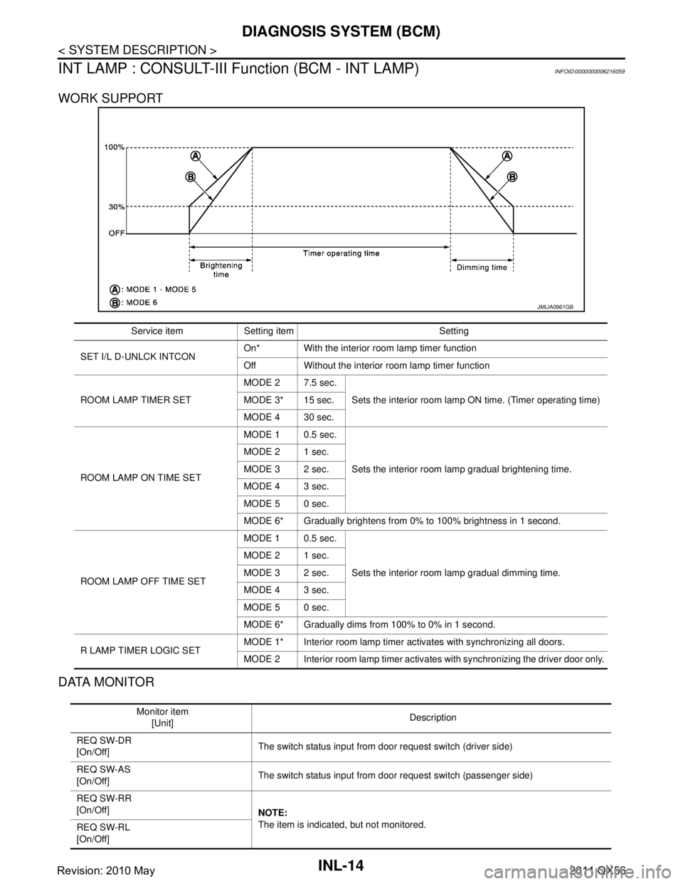
WORK SUPPORT
DATA MONITOR
JMLIA0961GB
Service item Setting item Setting
SET I/L D-UNLCK INTCON On* With the interior room lamp timer function
Off Without the interior room lamp timer function
ROOM LAMP TIMER SET MODE 2 7.5 sec.
Sets the interior room lamp ON time. (Timer operating time)
MODE 3* 15 sec.
MODE 4 30 sec.
ROOM LAMP ON TIME SET MODE 1 0.5 sec.
Sets the interior room lamp gradual brightening time.
MODE 2 1 sec.
MODE 3 2 sec.
MODE 4 3 sec.
MODE 5 0 sec.
MODE 6* Gradually brightens from 0% to 100% brightness in 1 second.
ROOM LAMP OFF TIME SET MODE 1 0.5 sec.
Sets the interior room lamp gradual dimming time.
MODE 2 1 sec.
MODE 3 2 sec.
MODE 4 3 sec.
MODE 5 0 sec.
MODE 6* Gradually dims from 100% to 0% in 1 second.
R LAMP TIMER LOGIC SET MODE 1* Interior room lamp timer activates with synchronizing all doors.
MODE 2 Interior room lamp timer activates with synchronizing the driver door only.
Monitor item
[Unit] Description
REQ SW-DR
[On/Off] The switch status input from door request switch (driver side)
REQ SW-AS
[On/Off] The switch status input from door request switch (passenger side)
REQ SW-RR
[On/Off] NOTE:
The item is indicated, but not monitored.
REQ SW-RL
[On/Off]
Revision: 2010 May2011 QX56
Page 3282 of 5598

DIAGNOSIS SYSTEM (BCM)INL-15
< SYSTEM DESCRIPTION >
C
DE
F
G H
I
J
K
M A
B
INL
N
O P
ACTIVE TEST
BATTERY SAVER
BATTERY SAVER : CONSULT-III Function (BCM - BATTERY SAVER)INFOID:0000000006216060
WORK SUPPORT
*:Factory setting PUSH SW
[On/Off]
The switch status input from push-button ignition switch
UNLK SEN -DR
[On/Off] Driver door unlock status input from unlock sensor
DOOR SW-DR
[On/Off] The switch status input from door switch (driver side)
DOOR SW-AS
[On/Off] The switch status input from door switch (passenger side)
DOOR SW-RR
[On/Off] The switch status input from rear door switch RH
DOOR SW- RL
[On/Off] The switch status input from rear door switch LH
DOOR SW- BK
[On/Off] The switch status input from back door switch
CDL LOCK SW
[On/Off] Lock switch status input from door lock and unlock switch
CDL UNLOCK SW
[On/Off] Unlock switch status input from door lock and unlock switch
KEY CYL LK-SW
[On/Off] Lock switch status received from door key cylinder switch
KEY CYL UN-SW
[On/Off] Unlock switch status received from door key cylinder switch
TRNK/HAT MNTR
[On/Off] NOTE:
The item is indicated, but not monitored.
RKE-LOCK
[On/Off] Lock signal status received from remote keyless entry receiver
RKE-UNLOCK
[On/Off] Unlock signal status received from remote keyless entry receiver
Monitor item
[Unit] Description
Test item Operation Description
INT LAMP OnOutputs the interior room lamp control signal to turn the interior room lamps ON.
[Map lamp, personal lamp, foot lamp (when applicable lamps switch is in DOOR po-
sition.)]
Off Stops the interior room lamp control signal to turn the interior room lamps OFF.
STEP LAMP TEST On Outputs the step lamp control signal to turn the step lamps ON.
Off Stops the step lamp control signal to turn the step lamps ON.
Service item Setting item Setting
ROOM LAMP TIMER SET MODE 1
*30 min.
Sets the interior room lamp battery saver timer operating
time.
MODE 2 60 min.
BATTERY SAVER SET On
*With the exterior lamp battery saver function
Off Without the exterior lamp battery saver function
Revision: 2010 May2011 QX56
Page 3349 of 5598

INL-82
< SERVICE DATA AND SPECIFICATIONS (SDS)
SERVICE DATA AND SPECIFICATIONS (SDS)
SERVICE DATA AND SPECIFICATIONS (SDS)
SERVICE DATA AND SPECIFICATIONS (SDS)
Bulb SpecificationsINFOID:0000000006288670
Item Type Wattage (W)
Push-button ignition switch illumination LED —
Map lamp Wedge 8
Console lamp
(integrated into the map lamp assembly) LED —
Puddle lamp LED —
Vanity mirror lamp — 2
Glove box lamp Wedge 1.4
Foot lamp (driver and passenger) Wedge 1.4
Rear foot lamp LED —
Mood lamp (front and rear door armrest) LED —
Ste p lam p We dg e 8
Personal lamp Wedge 8
Luggage room lamp — 8
Revision: 2010 May2011 QX56
Page 3350 of 5598

INT-1
BODY INTERIOR
C
DE
F
G H
I
K L
M
SECTION INT
A
B
INT
N
O P
CONTENTS
INTERIOR
PRECAUTION ................ ...............................3
PRECAUTIONS .............................................. .....3
Precaution for Supplemental Restraint System
(SRS) "AIR BAG" and "SEAT BELT PRE-TEN-
SIONER" ............................................................. ......
3
Precaution Necessary for Steering Wheel Rota-
tion after Battery Disconnect .....................................
3
Precaution for Procedure without Cowl Top Cover ......4
Precaution for Work ..................................................4
PREPARATION ............................................5
PREPARATION .............................................. .....5
Special Service Tools .......................................... ......5
Commercial Service Tools ........................................5
CLIP LIST ............................................................6
Clip List ............................................................... ......6
SYMPTOM DIAGNOSIS ...............................7
SQUEAK AND RATTLE TROUBLE DIAG-
NOSES ........................ ........................................
7
Work Flow ........................................................... ......7
Inspection Procedure ................................................9
Diagnostic Worksheet .............................................11
REMOVAL AND INSTALLATION ...............13
FRONT DOOR FINISHER .............................. ....13
Exploded View .................................................... ....13
Removal and Installation .........................................14
REAR DOOR FINISHER ....................................16
Exploded View .................................................... ....16
Removal and Installation .........................................16
BODY SIDE TRIM ..............................................18
Exploded View .................................................... ....18
DASH SIDE FINISHER .......................................... ....18
DASH SIDE FINISHER : Removal and Installation
....
18
FRONT PILLAR GARNISH .................................... ....19
FRONT PILLAR GARNISH : Removal and Instal-
lation ........................................................................
19
BODY SIDE WELT ................................................. ....20
BODY SIDE WELT : Removal and Installation ........20
KICKING PLATE INNER ....................................... ....20
KICKING PLATE INNER : Removal and Installa-
tion ...........................................................................
20
KICKING PLATE OUTER ...................................... ....21
KICKING PLATE OUTER : Removal and Installa-
tion ...........................................................................
21
CENTER PILLAR LOWER GARNISH ................... ....22
CENTER PILLAR LOWER GARNISH : Removal
and Installation ........................................................
22
CENTER PILLAR UPPER GARNISH ........................22
CENTER PILLAR UPPER GARNISH : Removal
and Installation .................................................... ....
22
FLOOR TRIM ....................................................24
Exploded View .........................................................24
FRONT FLOOR CARPET ...................................... ....25
FRONT FLOOR CARPET : Removal and Installa-
tion ....................................................................... ....
25
REAR FLOOR CARPET ........................................ ....27
REAR FLOOR CARPET : Removal and Installa-
tion ...........................................................................
27
HEADLINING ....................................................28
Exploded View .........................................................28
Removal and Installation .........................................29
LUGGAGE FLOOR TRIM .................................33
Exploded View .........................................................33
Revision: 2010 May2011 QX56
Page 3352 of 5598
PRECAUTIONSINT-3
< PRECAUTION >
C
DE
F
G H
I
K L
M A
B
INT
N
O P
PRECAUTION
PRECAUTIONS
Precaution for Supplemental Restraint System (SRS) "AIR BAG" and "SEAT BELT
PRE-TENSIONER"
INFOID:0000000006415653
The Supplemental Restraint System such as “A IR BAG” and “SEAT BELT PRE-TENSIONER”, used along
with a front seat belt, helps to reduce the risk or severi ty of injury to the driver and front passenger for certain
types of collision. This system includes seat belt switch inputs and dual stage front air bag modules. The SRS
system uses the seat belt switches to determine the front air bag deployment, and may only deploy one front
air bag, depending on the severity of a collision and whether the front occupants are belted or unbelted.
Information necessary to service the system safely is included in the “SRS AIR BAG” and “SEAT BELT” of this
Service Manual.
WARNING:
• To avoid rendering the SRS inoper ative, which could increase the risk of personal injury or death in
the event of a collision that would result in air ba g inflation, all maintenance must be performed by
an authorized NISSAN/INFINITI dealer.
Improper maintenance, including in correct removal and installation of the SRS, can lead to personal
injury caused by unintentional act ivation of the system. For removal of Spiral Cable and Air Bag
Module, see the “SRS AIR BAG”.
Do not use electrical test equipm ent on any circuit related to the SRS unless instructed to in this
Service Manual. SRS wiring harnesses can be identi fied by yellow and/or orange harnesses or har-
ness connectors.
PRECAUTIONS WHEN USING POWER TOOLS (AIR OR ELECTRIC) AND HAMMERS
WARNING:
When working near the Air Bag Diagnosis Sensor Unit or other Air Bag System sensors with the
ignition ON or engine running, DO NOT use air or electric power tools or strike near the sensor(s)
with a hammer. Heavy vibration could activate the sensor(s) and deploy the air bag(s), possibly
causing serious injury.
When using air or electric power tools or hammers , always switch the ignition OFF, disconnect the
battery, and wait at least 3 minutes before performing any service.
Precaution Necessary for Steering Wh eel Rotation after Battery Disconnect
INFOID:0000000006415652
NOTE:
Before removing and installing any control units, first tu rn the push-button ignition switch to the LOCK posi-
tion, then disconnect both battery cables.
After finishing work, confirm that all control unit connectors are connected properly, then re-connect both
battery cables.
Always use CONSULT-III to perform self-diagnosis as a part of each function inspection after finishing work.
If a DTC is detected, perform trouble diagnos is according to self-diagnosis results.
For vehicle with steering lock unit, if the battery is disconnected or discharged, the steering wheel will lock and
cannot be turned.
If turning the steering wheel is required with the batte ry disconnected or discharged, follow the operation pro-
cedure below before starting the repair operation.
OPERATION PROCEDURE
1. Connect both battery cables. NOTE:
Supply power using jumper cables if battery is discharged.
2. Turn the push-button ignition switch to ACC position. (At this time, the steering lock will be released.)
3. Disconnect both battery cables. The steering lock wil l remain released with both battery cables discon-
nected and the steering wheel can be turned.
4. Perform the necessary repair operation.
Revision: 2010 May2011 QX56
Page 3354 of 5598
PREPARATIONINT-5
< PREPARATION >
C
DE
F
G H
I
K L
M A
B
INT
N
O P
PREPARATION
PREPARATION
Special Service ToolsINFOID:0000000006220267
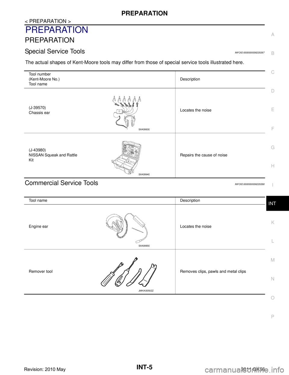
The actual shapes of Kent-Moore tools may differ fr om those of special service tools illustrated here.
Commercial Service ToolsINFOID:0000000006220268
Tool number
(Kent-Moore No.)
Tool name Description
(J-39570)
Chassis ear Locates the noise
(J-43980)
NISSAN Squeak and Rattle
Kit Repairs the cause of noise
SIIA0993E
SIIA0994E
Tool name
Description
Engine ear Locates the noise
Remover tool Removes clips, pawls and metal clips
SIIA0995E
JMKIA3050ZZ
Revision: 2010 May2011 QX56
Page 3356 of 5598
SQUEAK AND RATTLE TROUBLE DIAGNOSESINT-7
< SYMPTOM DIAGNOSIS >
C
DE
F
G H
I
K L
M A
B
INT
N
O P
SYMPTOM DIAGNOSIS
SQUEAK AND RATTLE TROUBLE DIAGNOSES
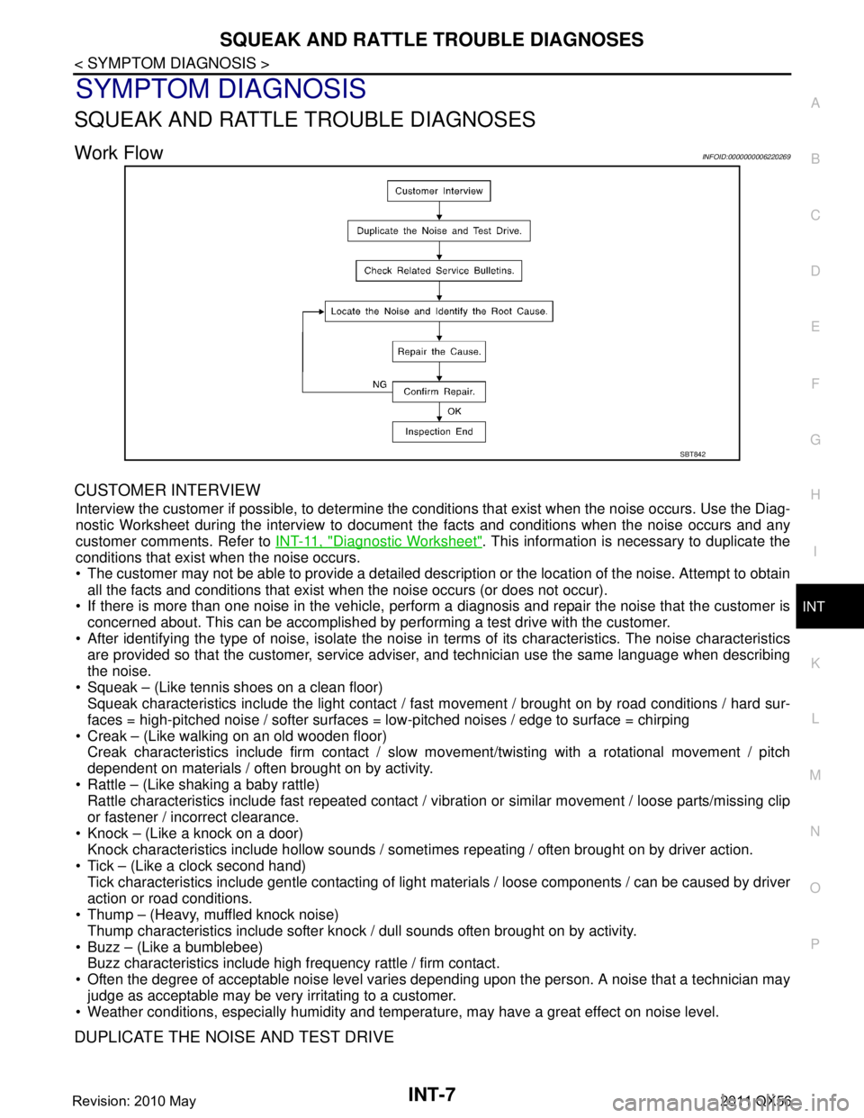
Work FlowINFOID:0000000006220269
CUSTOMER INTERVIEW
Interview the customer if possible, to determine the conditions that exist when the noise occurs. Use the Diag-
nostic Worksheet during the interv iew to document the facts and conditions when the noise occurs and any
customer comments. Refer to INT-11, "
Diagnostic Worksheet". This information is necessary to duplicate the
conditions that exist when the noise occurs.
The customer may not be able to provide a detailed description or the location of the noise. Attempt to obtain
all the facts and conditions that exist when the noise occurs (or does not occur).
If there is more than one noise in the vehicle, perform a diagnosis and repair the noise that the customer is
concerned about. This can be accomplished by performing a test drive with the customer.
After identifying the type of noise, isolate the noise in terms of its characteristics. The noise characteristics
are provided so that the customer, service advis er, and technician use the same language when describing
the noise.
Squeak – (Like tennis shoes on a clean floor) Squeak characteristics include the light contact / fast movement / brought on by road conditions / hard sur-
faces = high-pitched noise / softer surfaces = low-pitched noises / edge to surface = chirping
Creak – (Like walking on an old wooden floor) Creak characteristics include firm contact / slow mo vement/twisting with a rotational movement / pitch
dependent on materials / often brought on by activity.
Rattle – (Like shaking a baby rattle) Rattle characteristics include fast repeated contact / vi bration or similar movement / loose parts/missing clip
or fastener / incorrect clearance.
Knock – (Like a knock on a door) Knock characteristics include hollow sounds / someti mes repeating / often brought on by driver action.
Tick – (Like a clock second hand) Tick characteristics include gentle contacting of light materials / loose components / can be caused by driver
action or road conditions.
Thump – (Heavy, muffled knock noise)
Thump characteristics include softer knock / dull sounds often brought on by activity.
Buzz – (Like a bumblebee) Buzz characteristics include high frequency rattle / firm contact.
Often the degree of acceptable noise level varies depending upon the person. A noise that a technician may
judge as acceptable may be very irritating to a customer.
Weather conditions, especially humidity and temperat ure, may have a great effect on noise level.
DUPLICATE THE NOISE AND TEST DRIVE
SBT842
Revision: 2010 May2011 QX56