2011 INFINITI QX56 service
[x] Cancel search: servicePage 3074 of 5598
HA-18
< BASIC INSPECTION >
REFRIGERANT
REFRIGERANT
DescriptionINFOID:0000000006276149
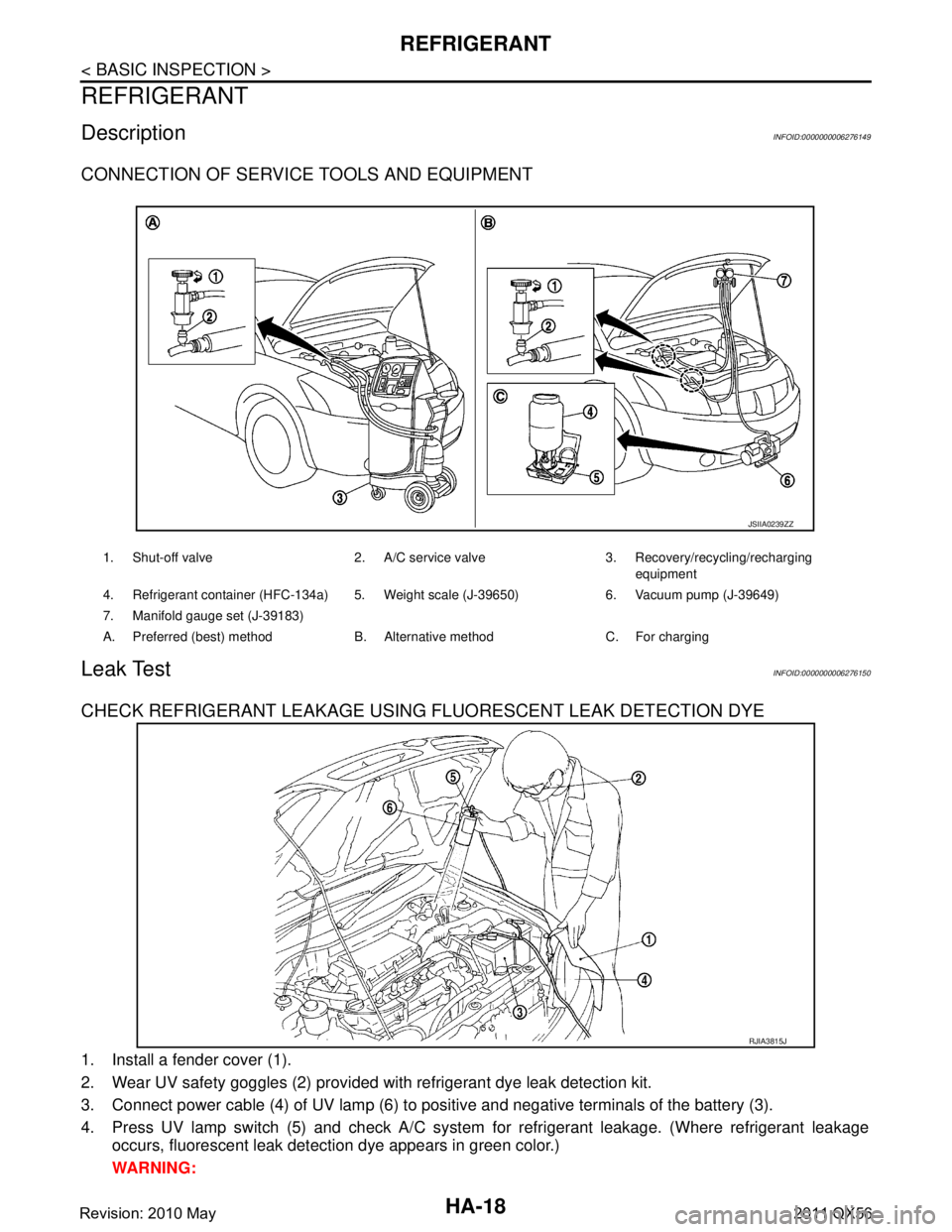
CONNECTION OF SERVICE TOOLS AND EQUIPMENT
Leak TestINFOID:0000000006276150
CHECK REFRIGERANT LEAKAGE USING FLUORESCENT LEAK DETECTION DYE
1. Install a fender cover (1).
2. Wear UV safety goggles (2) provided with refrigerant dye leak detection kit.
3. Connect power cable (4) of UV lamp (6) to positive and negative terminals of the battery (3).
4. Press UV lamp switch (5) and check A/C system for refrigerant leakage. (Where refrigerant leakage
occurs, fluorescent leak detec tion dye appears in green color.)
WARNING:
1. Shut-off valve 2. A/C service valve 3. Recovery/recycling/recharging equipment
4. Refrigerant container (HFC-134a) 5. Weight scale (J-39650) 6. Vacuum pump (J-39649)
7. Manifold gauge set (J-39183)
A. Preferred (best) method B. Alternative method C. For charging
JSIIA0239ZZ
RJIA3815J
Revision: 2010 May2011 QX56
Page 3075 of 5598
REFRIGERANTHA-19
< BASIC INSPECTION >
C
DE
F
G H
J
K L
M A
B
HA
N
O P
Never look directly into UV lamp light source.
NOTE:
For continuous operating time of UV lamp, fo llow the manufacturer operating instructions.
Illuminate piping joints from different angles us ing UV lamp and check that there is no leakage.
Use a mirror in area that is difficult to see to check refrigerant leakage.
Refrigerant leakage from evaporator can be detected by soaking cotton swab or a similar material with
drain hose water and illuminating it using UV lamp.
Dust, dirt, and packing materials adhesive used for condenser, evaporator, and other locations may flu- oresce. Be careful not to misidentify leakage.
5. Repair or replace parts where refrigerant leak age occurs and wipe off fluorescent leak detection dye.
NOTE:
Completely wipe off fluorescent leak detection dy e from gaps between parts, screw threads, and others
using a cotton swab or similar materials.
6. Use a UV lamp to check that no fluorescent leak detection dye remains after finishing work. WARNING:
Never look directly into UV lamp light source.
NOTE:
For continuous operating time of UV lamp, fo llow the manufacturer operating instructions.
Dust, dirt, and packing materials adhesive used for condenser, evaporator, and other locations may flu-
oresce. Be careful not to misidentify leakage.
CHECK REFRIGERANT LEAKAGE USIN G ELECTRICAL LEAK DETECTOR
WARNING:
Never check refrigerant leakage while the engine is running.
CAUTION:
Be careful of the following items so that in accurate checks or misidentifications are avoided.
Never allow refrigerant vapor, shop chemical vapors, cigarette smoke, or others around the vehicle.
Always check refrigerant leakage in a low air flow environment so that refrigerant may not disperse
when leakage occurs.
1. Stop the engine.
2. Connect recovery/recycling/recharging equipment or manifold gauge set to A/C service valve.
3. Check that A/C refrigerant pressure is 345 kPa (3.52 kg/cm
2, 50 psi) or more when temperature is 16 °C
(61 °F) or more. When pressure is lower than the spec ified value, recycle refrigerant completely and fill
refrigerant to the specified level.
NOTE:
Leakages may not be detected if A/C refri gerant pressure is 345 kPa (3.52 kg/cm
2, 50 psi) or less when
temperature is less than 16 °C (61 °F).
4. Clean area where refrigerant leakage check is per formed, and check refrigerant leakage along all sur-
faces of pipe connections and A/C system com ponents using electrical leak detector probe.
CAUTION:
Continue checking when a leakage is found. Always continue and complete checking along all
pipe connections and A/C system co mponents for additional leakage.
When a leakage is detected, clean leakage area using compressed air and check again.
When checking leakage of cooling unit inside, al ways clean inside of drain hose so that the
probe surface may not be exposed to water or dirt.
NOTE:
Always check leakage starting from high-pressure side and continue to low-pressure side.
When checking leakage of cooling unit inside, operate blower fan motor for 15 minutes or more at the maximum fan speed while the engine is stopped, and then insert electrical leak detector probe into drain
hose and hold for 10 minutes or more.
When disconnecting shut-off valve that is connected to A/C service valve, always evacuate remaining
refrigerant so that misidentification can be avoided.
5. Repair or replace parts where refrigerant leak age is detected. (Leakage is detected but leakage area is
unknown. GO TO 6.)
6. Start the engine and set A/C control in the following conditions. A/C switch ON
Air flow: VENT (ventilation)
Intake door position: Recirculation
Revision: 2010 May2011 QX56
Page 3076 of 5598
HA-20
< BASIC INSPECTION >
REFRIGERANT
Temperature setting: Full cold
Fan speed: Maximum speed set
7. Run the engine at approximately 1,500 rpm for 2 minutes or more.
8. Stop the engine. Check again for refrigerant leakage. GO TO 4.
WARNING:
Be careful not to get burned when the engine is hot.
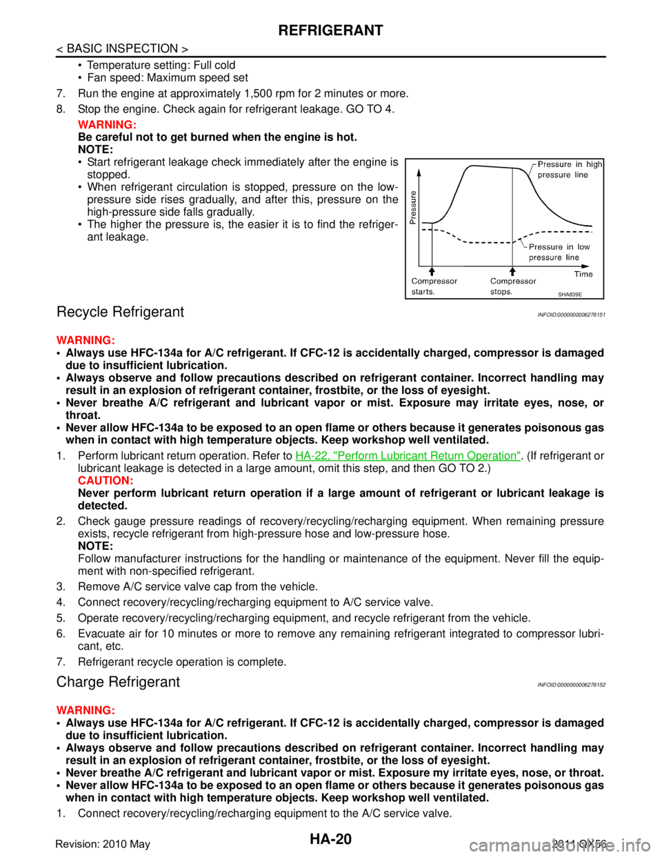
NOTE:
Start refrigerant leakage check immediately after the engine is stopped.
When refrigerant circulation is stopped, pressure on the low-
pressure side rises gradually, and after this, pressure on the
high-pressure side falls gradually.
The higher the pressure is, the easier it is to find the refriger-
ant leakage.
Recycle RefrigerantINFOID:0000000006276151
WARNING:
Always use HFC-134a for A/C refrigerant. If CFC-12 is accidentally charged, compressor is damaged
due to insufficient lubrication.
Always observe and follow precaution s described on refrigerant container. Incorrect handling may
result in an explosion of refrigerant co ntainer, frostbite, or the loss of eyesight.
Never breathe A/C refrigerant and lubricant vapor or mist. Exposure may irritate eyes, nose, or
throat.
Never allow HFC-134a to be exposed to an open flam e or others because it generates poisonous gas
when in contact with high temperature ob jects. Keep workshop well ventilated.
1. Perform lubricant return operation. Refer to HA-22, "
Perform Lubricant Return Operation". (If refrigerant or
lubricant leakage is detected in a large am ount, omit this step, and then GO TO 2.)
CAUTION:
Never perform lubricant return op eration if a large amount of refrigerant or lubricant leakage is
detected.
2. Check gauge pressure readings of recovery/recyc ling/recharging equipment. When remaining pressure
exists, recycle refrigerant from high-pressure hose and low-pressure hose.
NOTE:
Follow manufacturer instructions for the handling or maintenance of the equipment. Never fill the equip-
ment with non-specified refrigerant.
3. Remove A/C service valve cap from the vehicle.
4. Connect recovery/recycling/rechargi ng equipment to A/C service valve.
5. Operate recovery/recycling/recharging equipm ent, and recycle refrigerant from the vehicle.
6. Evacuate air for 10 minutes or more to remove any remaining refrigerant integrated to compressor lubri-
cant, etc.
7. Refrigerant recycle operation is complete.
Charge RefrigerantINFOID:0000000006276152
WARNING:
Always use HFC-134a for A/C refrigerant. If CFC-12 is accidentally charged, compressor is damaged
due to insufficient lubrication.
Always observe and follow precaution s described on refrigerant container. Incorrect handling may
result in an explosion of refrigerant co ntainer, frostbite, or the loss of eyesight.
Never breathe A/C refrigerant and lubricant vapor or mist. Exposure my irritate eyes, nose, or throat.
Never allow HFC-134a to be exposed to an open flam e or others because it generates poisonous gas
when in contact with high temperature ob jects. Keep workshop well ventilated.
1. Connect recovery/recycling/recharging equipment to the A/C service valve.
SHA839E
Revision: 2010 May2011 QX56
Page 3077 of 5598
REFRIGERANTHA-21
< BASIC INSPECTION >
C
DE
F
G H
J
K L
M A
B
HA
N
O P
2. Operate recovery/recycling/recharging equipment, and evacuate air from A/C system for 25 minutes or
more.
CAUTION:
Evacuate air for 15 minutes or mo re if the parts are replaced.
3. Check the airtightness of A/C system for 25 minutes or more. If pressure rises more than the specified
level, charge A/C system with approximately 200 g (0.4 lb) refrigerant and check that there is no refriger-
ant leakage. Refer to HA-18, "
Leak Test".
CAUTION:
Check the airtightness for 15 minutes or more if the parts are replaced.
4. If parts other than compressor are replaced, fill comp ressor lubricant according to parts that are replaced.
5. Charge the specified amount of refrigerant to A/C system.
6. Check that A/C system operates normally.
7. Disconnect recovery/recycling/recharging equipment. (Co llect the refrigerant from the high-pressure hose
and low-pressure hose of recove ry/recycling/recharging equipment.)
8. Install A/C service valve cap.
9. Refrigerant charge is complete.
Revision: 2010 May2011 QX56
Page 3106 of 5598
HA-50
< SERVICE DATA AND SPECIFICATIONS (SDS)
SERVICE DATA AND SPECIFICATIONS (SDS)
SERVICE DATA AND SPECIFICATIONS (SDS)
SERVICE DATA AND SPECIFICATIONS (SDS)
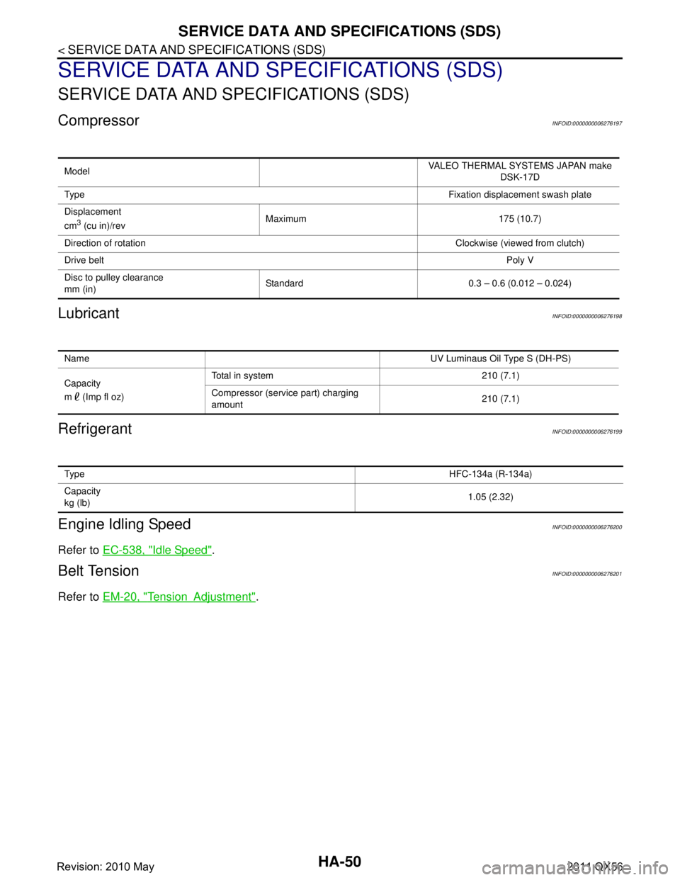
CompressorINFOID:0000000006276197
LubricantINFOID:0000000006276198
RefrigerantINFOID:0000000006276199
Engine Idling SpeedINFOID:0000000006276200
Refer to EC-538, "Idle Speed".
Belt TensionINFOID:0000000006276201
Refer to EM-20, "TensionAdjustment".
Model VALEO THERMAL SYSTEMS JAPAN make
DSK-17D
Ty p e Fixation displacement swash plate
Displacement
cm
3 (cu in)/rev Maximum 175 (10.7)
Direction of rotation Clockwise (viewed from clutch)
Drive belt Poly V
Disc to pulley clearance
mm (in) Standard 0.3 – 0.6 (0.012 – 0.024)
Name
UV Luminaus Oil Type S (DH-PS)
Capacity
m (Imp fl oz) Total in system 210 (7.1)
Compressor (service part) charging
amount
210 (7.1)
Ty p e
HFC-134a (R-134a)
Capacity
kg (lb) 1.05 (2.32)
Revision: 2010 May2011 QX56
Page 3111 of 5598
![INFINITI QX56 2011 Factory Service Manual
PRECAUTIONSHAC-5
< PRECAUTION > [AUTOMATIC AIR CONDITIONING]
C
D
E
F
G H
J
K L
M A
B
HAC
N
O P
PRECAUTION
PRECAUTIONS
Precaution for Supplemental Restraint System (SRS) "AIR BAG" and "SEAT BELT
PRE INFINITI QX56 2011 Factory Service Manual
PRECAUTIONSHAC-5
< PRECAUTION > [AUTOMATIC AIR CONDITIONING]
C
D
E
F
G H
J
K L
M A
B
HAC
N
O P
PRECAUTION
PRECAUTIONS
Precaution for Supplemental Restraint System (SRS) "AIR BAG" and "SEAT BELT
PRE](/manual-img/42/57033/w960_57033-3110.png)
PRECAUTIONSHAC-5
< PRECAUTION > [AUTOMATIC AIR CONDITIONING]
C
D
E
F
G H
J
K L
M A
B
HAC
N
O P
PRECAUTION
PRECAUTIONS
Precaution for Supplemental Restraint System (SRS) "AIR BAG" and "SEAT BELT
PRE-TENSIONER"
INFOID:0000000006275847
The Supplemental Restraint System such as “A IR BAG” and “SEAT BELT PRE-TENSIONER”, used along
with a front seat belt, helps to reduce the risk or severi ty of injury to the driver and front passenger for certain
types of collision. This system includes seat belt switch inputs and dual stage front air bag modules. The SRS
system uses the seat belt switches to determine the front air bag deployment, and may only deploy one front
air bag, depending on the severity of a collision and whether the front occupants are belted or unbelted.
Information necessary to service the system safely is included in the “SRS AIR BAG” and “SEAT BELT” of this
Service Manual.
WARNING:
• To avoid rendering the SRS inoper ative, which could increase the risk of personal injury or death in
the event of a collision that would result in air ba g inflation, all maintenance must be performed by
an authorized NISSAN/INFINITI dealer.
Improper maintenance, including in correct removal and installation of the SRS, can lead to personal
injury caused by unintentional act ivation of the system. For removal of Spiral Cable and Air Bag
Module, see the “SRS AIR BAG”.
Do not use electrical test equipm ent on any circuit related to the SRS unless instructed to in this
Service Manual. SRS wiring harnesses can be identi fied by yellow and/or orange harnesses or har-
ness connectors.
PRECAUTIONS WHEN USING POWER TOOLS (AIR OR ELECTRIC) AND HAMMERS
WARNING:
When working near the Air Bag Diagnosis Sensor Unit or other Air Bag System sensors with the
ignition ON or engine running, DO NOT use air or electric power tools or strike near the sensor(s)
with a hammer. Heavy vibration could activate the sensor(s) and deploy the air bag(s), possibly
causing serious injury.
When using air or electric power tools or hammers , always switch the ignition OFF, disconnect the
battery, and wait at least 3 minutes before performing any service.
Revision: 2010 May2011 QX56
Page 3263 of 5598
HRN-2
< PRECAUTION >
PRECAUTIONS
PRECAUTION
PRECAUTIONS
Precaution for Supplemental Restraint System (SRS) "AIR BAG" and "SEAT BELT
PRE-TENSIONER"
INFOID:0000000006220273
The Supplemental Restraint System such as “A IR BAG” and “SEAT BELT PRE-TENSIONER”, used along
with a front seat belt, helps to reduce the risk or severi ty of injury to the driver and front passenger for certain
types of collision. This system includes seat belt switch inputs and dual stage front air bag modules. The SRS
system uses the seat belt switches to determine the front air bag deployment, and may only deploy one front
air bag, depending on the severity of a collision and w hether the front occupants are belted or unbelted.
Information necessary to service the system safely is included in the “SRS AIR BAG” and “SEAT BELT” of this
Service Manual.
WARNING:
• To avoid rendering the SRS inopera tive, which could increase the risk of personal injury or death in
the event of a collision that would result in air bag inflation, all maintenance must be performed by
an authorized NISS AN/INFINITI dealer.
Improper maintenance, including in correct removal and installation of the SRS, can lead to personal
injury caused by unintent ional activation of the system. For re moval of Spiral Cable and Air Bag
Module, see the “SRS AIR BAG”.
Do not use electrical test equipmen t on any circuit related to the SRS unless instructed to in this
Service Manual. SRS wiring harnesses can be identi fied by yellow and/or orange harnesses or har-
ness connectors.
PRECAUTIONS WHEN USING POWER TOOLS (AIR OR ELECTRIC) AND HAMMERS
WARNING:
When working near the Air Bag Diagnosis Sensor Unit or other Air Bag System sensors with the ignition ON or engine running, DO NOT use air or electric power tools or strike near the sensor(s)
with a hammer. Heavy vibration could activate the sensor(s) and deploy the air bag(s), possibly
causing serious injury.
When using air or electric power tools or hammers , always switch the ignition OFF, disconnect the
battery, and wait at least 3 minu tes before performing any service.
Revision: 2010 May2011 QX56
Page 3269 of 5598

INL-2
LUGGAGE ROOM LAMP CIRCUIT ..................60
Description ........................................................... ...60
Diagnosis Procedure ..............................................60
STEP LAMP CIRCUIT .......................................62
Description ........................................................... ...62
Component Function Check ...................................62
Diagnosis Procedure ..............................................62
PUDDLE LAMP CIRCUIT ..................................64
Description ........................................................... ...64
Diagnosis Procedure ..............................................64
PUSH-BUTTON IGNITION SWITCH ILLUMI-
NATION CIRCUIT ..............................................
65
Component Function Check ................................ ...65
Diagnosis Procedure ..............................................65
SYMPTOM DIAGNOSIS .............................67
INTERIOR LIGHTING SYSTEM SYMPTOMS ...67
Symptom Table ................................................... ...67
REMOVAL AND INSTALLATION ...............68
MAP LAMP ..................................................... ...68
Exploded View ..................................................... ...68
Removal and Installation ........................................68
Replacement ..........................................................68
VANITY MIRROR LAMP ...................................69
Exploded View ..................................................... ...69
Replacement ..........................................................69
GLOVE BOX LAMP ...........................................70
Exploded View ..................................................... ...70
Replacement ..........................................................70
FOOT LAMP ......................................................71
DRIVER SIDE ......................................................... ...71
DRIVER SIDE : Exploded View ..............................71
DRIVER SIDE : Replacement ................................71
PASSENGER SIDE ...................................................71
PASSENGER SIDE : Exploded View .....................71
PASSENGER SIDE : Replac ement ........................72
REAR FOOT LAMP ................................................ ...72
REAR FOOT LAMP : Exploded View .....................72
REAR FOOT LAMP : Removal and Installation ......72
STEP LAMP .......................................................74
Exploded View ..................................................... ...74
Removal and Installation .........................................74
Replacement ...........................................................74
MOOD LAMP .....................................................75
FRONT DOOR ARMREST ..................................... ...75
FRONT DOOR ARMREST : Exploded View ..........75
FRONT DOOR ARMREST : Replacement .............75
REAR DOOR ARMREST ....................................... ...75
REAR DOOR ARMREST : Exploded View .............75
REAR DOOR ARMREST : Replacement ...............76
PERSONAL LAMP ............................................77
Exploded View ..................................................... ...77
Removal and Installation .........................................77
Replacement ...........................................................78
PUDDLE LAMP .............................................. ...79
Exploded View ..................................................... ...79
Removal and Installation .........................................79
LUGGAGE ROOM LAMP ..................................81
Exploded View ..................................................... ...81
Removal and Installation .........................................81
Replacement ...........................................................81
SERVICE DATA AND SPECIFICATIONS
(SDS) .......... ................................................
82
SERVICE DATA AND SPECIFICATIONS
(SDS) .............................................................. ...
82
Bulb Specifications ............................................... ...82
Revision: 2010 May2011 QX56