2011 INFINITI QX56 keyless entry
[x] Cancel search: keyless entryPage 1711 of 5598
DOOR DOES NOT LOCK/UNLOCK WITH INTELLIGENT KEYDLK-175
< SYMPTOM DIAGNOSIS >
C
DE
F
G H
I
J
L
M A
B
DLK
N
O P
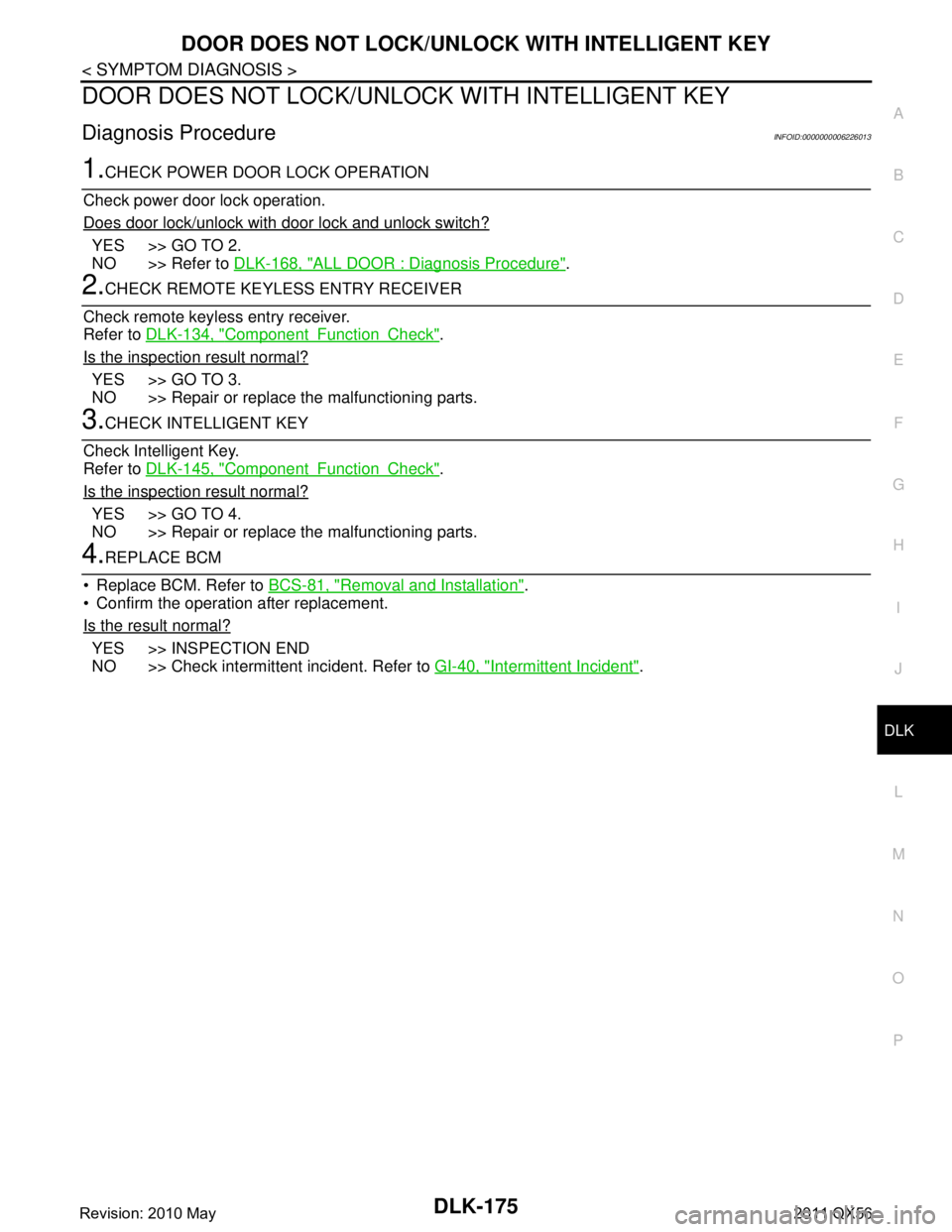
DOOR DOES NOT LOCK/UNLOCK WITH INTELLIGENT KEY
Diagnosis ProcedureINFOID:0000000006226013
1.CHECK POWER DOOR LOCK OPERATION
Check power door lock operation.
Does door lock/unlock with door lock and unlock switch?
YES >> GO TO 2.
NO >> Refer to DLK-168, "
ALL DOOR : Diagnosis Procedure".
2.CHECK REMOTE KEYLESS ENTRY RECEIVER
Check remote keyless entry receiver.
Refer to DLK-134, "
ComponentFunctionCheck".
Is the inspection result normal?
YES >> GO TO 3.
NO >> Repair or replace the malfunctioning parts.
3.CHECK INTELLIGENT KEY
Check Intelligent Key.
Refer to DLK-145, "
ComponentFunctionCheck".
Is the inspection result normal?
YES >> GO TO 4.
NO >> Repair or replace the malfunctioning parts.
4.REPLACE BCM
Replace BCM. Refer to BCS-81, "
Removal and Installation".
Confirm the operation after replacement.
Is the result normal?
YES >> INSPECTION END
NO >> Check intermittent incident. Refer to GI-40, "
Intermittent Incident".
Revision: 2010 May2011 QX56
Page 1722 of 5598
DLK-186
< SYMPTOM DIAGNOSIS >
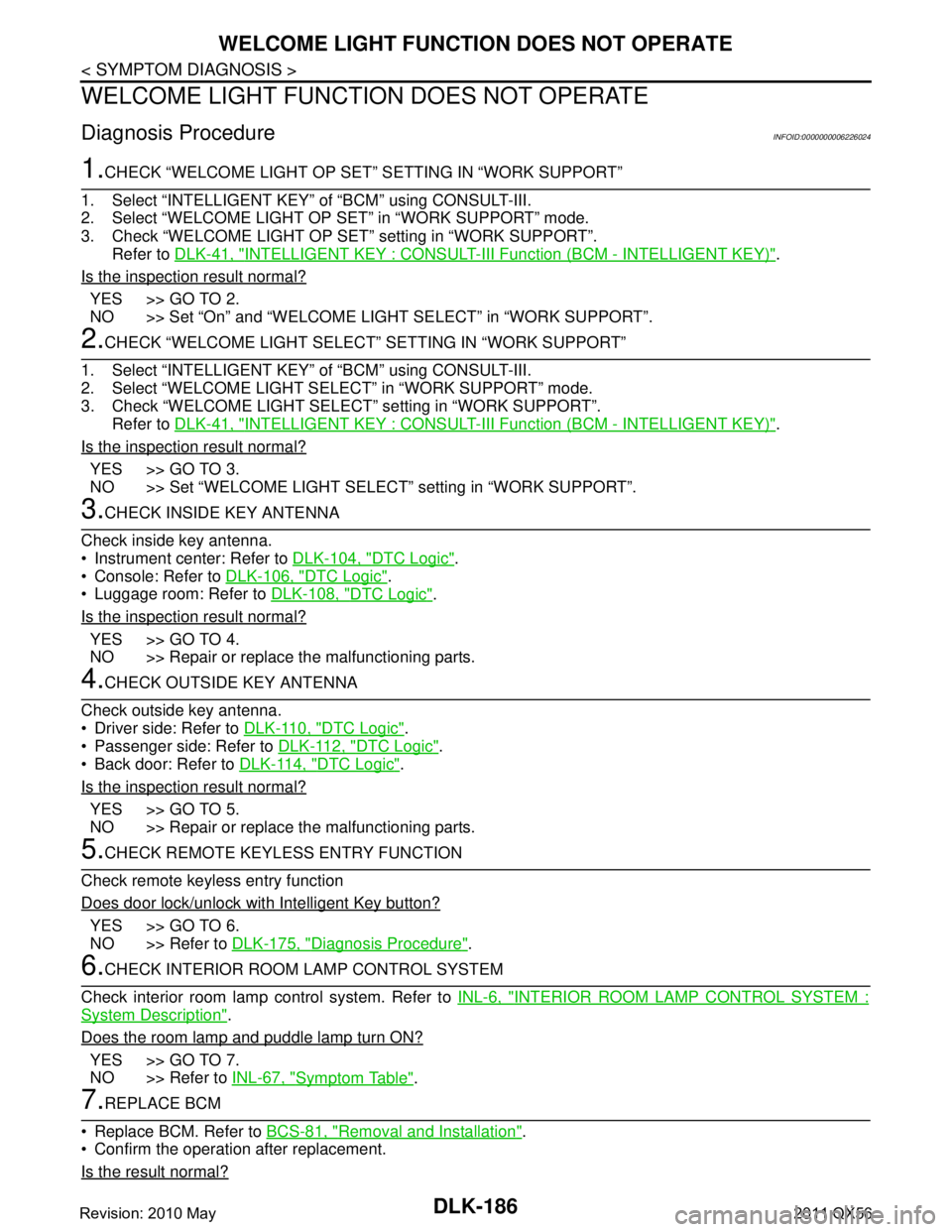
WELCOME LIGHT FUNCTION DOES NOT OPERATE
WELCOME LIGHT FUNCTION DOES NOT OPERATE
Diagnosis ProcedureINFOID:0000000006226024
1.CHECK “WELCOME LIGHT OP SET” SETTING IN “WORK SUPPORT”
1. Select “INTELLIGE NT KEY” of “BCM” using CONSULT-III.
2. Select “WELCOME LIGHT OP SET” in “WORK SUPPORT” mode.
3. Check “WELCOME LIGHT OP SET” setting in “WORK SUPPORT”. Refer to DLK-41, "
INTELLIGENT KEY : CONSULT-III F unction (BCM - INTELLIGENT KEY)".
Is the inspection result normal?
YES >> GO TO 2.
NO >> Set “On” and “WELCOME LIGHT SELECT” in “WORK SUPPORT”.
2.CHECK “WELCOME LIGHT SELECT” SETTING IN “WORK SUPPORT”
1. Select “INTELLIGE NT KEY” of “BCM” using CONSULT-III.
2. Select “WELCOME LIGHT SEL ECT” in “WORK SUPPORT” mode.
3. Check “WELCOME LIGHT SELECT ” setting in “WORK SUPPORT”.
Refer to DLK-41, "
INTELLIGENT KEY : CONSULT-III F unction (BCM - INTELLIGENT KEY)".
Is the inspection result normal?
YES >> GO TO 3.
NO >> Set “WELCOME LIGHT SELECT” setting in “WORK SUPPORT”.
3.CHECK INSIDE KEY ANTENNA
Check inside key antenna.
Instrument center: Refer to DLK-104, "
DTC Logic".
Console: Refer to DLK-106, "
DTC Logic".
Luggage room: Refer to DLK-108, "
DTC Logic".
Is the inspection result normal?
YES >> GO TO 4.
NO >> Repair or replace the malfunctioning parts.
4.CHECK OUTSIDE KEY ANTENNA
Check outside key antenna.
Driver side: Refer to DLK-110, "
DTC Logic".
Passenger side: Refer to DLK-112, "
DTC Logic".
Back door: Refer to DLK-114, "
DTC Logic".
Is the inspection result normal?
YES >> GO TO 5.
NO >> Repair or replace the malfunctioning parts.
5.CHECK REMOTE KEYL ESS ENTRY FUNCTION
Check remote keyless entry function
Does door lock/unlock with Intelligent Key button?
YES >> GO TO 6.
NO >> Refer to DLK-175, "
Diagnosis Procedure".
6.CHECK INTERIOR ROOM LAMP CONTROL SYSTEM
Check interior room lamp control system. Refer to INL-6, "
INTERIOR ROOM LAMP CONTROL SYSTEM :
System Description".
Does the room lamp and puddle lamp turn ON?
YES >> GO TO 7.
NO >> Refer to INL-67, "
Symptom Table".
7.REPLACE BCM
Replace BCM. Refer to BCS-81, "
Removal and Installation".
Confirm the operation after replacement.
Is the result normal?
Revision: 2010 May2011 QX56
Page 1736 of 5598
DLK-200
< SYMPTOM DIAGNOSIS >
AUTOMATIC BACK DOOR OPERATION DOES NOT OPERATE
1. Replace automatic back door control module. Refer to DLK-262, "Removal and Installation".
2. Confirm the operation after replacement.
Is the result normal?
YES >> INSPECTION END
NO >> Check intermittent incident. Refer to GI-40, "
Intermittent Incident".
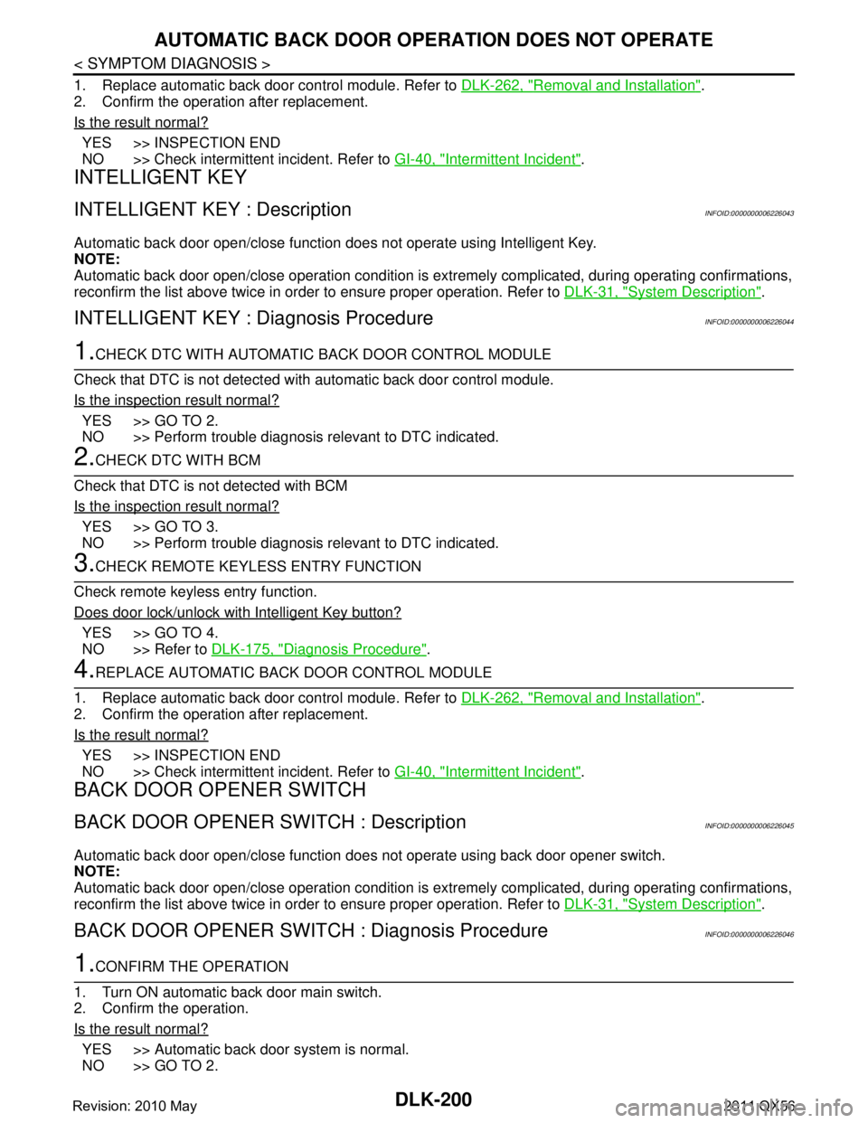
INTELLIGENT KEY
INTELLIGENT KEY : DescriptionINFOID:0000000006226043
Automatic back door open/close function does not operate using Intelligent Key.
NOTE:
Automatic back door open/close operation condition is ex tremely complicated, during operating confirmations,
reconfirm the list above twice in order to ensure proper operation. Refer to DLK-31, "
System Description".
INTELLIGENT KEY : Diagnosis ProcedureINFOID:0000000006226044
1.CHECK DTC WITH AUTOMATIC BACK DOOR CONTROL MODULE
Check that DTC is not detected with automatic back door control module.
Is the inspection result normal?
YES >> GO TO 2.
NO >> Perform trouble diagnosis relevant to DTC indicated.
2.CHECK DTC WITH BCM
Check that DTC is not detected with BCM
Is the inspection result normal?
YES >> GO TO 3.
NO >> Perform trouble diagnosis relevant to DTC indicated.
3.CHECK REMOTE KEYL ESS ENTRY FUNCTION
Check remote keyless entry function.
Does door lock/unlock with Intelligent Key button?
YES >> GO TO 4.
NO >> Refer to DLK-175, "
Diagnosis Procedure".
4.REPLACE AUTOMATIC BACK DOOR CONTROL MODULE
1. Replace automatic back door control module. Refer to DLK-262, "
Removal and Installation".
2. Confirm the operation after replacement.
Is the result normal?
YES >> INSPECTION END
NO >> Check intermittent incident. Refer to GI-40, "
Intermittent Incident".
BACK DOOR OPENER SWITCH
BACK DOOR OPENER SWITCH : DescriptionINFOID:0000000006226045
Automatic back door open/close function does not operate using back door opener switch.
NOTE:
Automatic back door open/close operation condition is ex tremely complicated, during operating confirmations,
reconfirm the list above twice in order to ensure proper operation. Refer to DLK-31, "
System Description".
BACK DOOR OPENER SWITCH : Diagnosis ProcedureINFOID:0000000006226046
1.CONFIRM THE OPERATION
1. Turn ON automatic back door main switch.
2. Confirm the operation.
Is the result normal?
YES >> Automatic back door system is normal.
NO >> GO TO 2.
Revision: 2010 May2011 QX56
Page 1795 of 5598
REMOTE KEYLESS ENTRY RECEIVERDLK-259
< REMOVAL AND INSTALLATION >
C
DE
F
G H
I
J
L
M A
B
DLK
N
O P
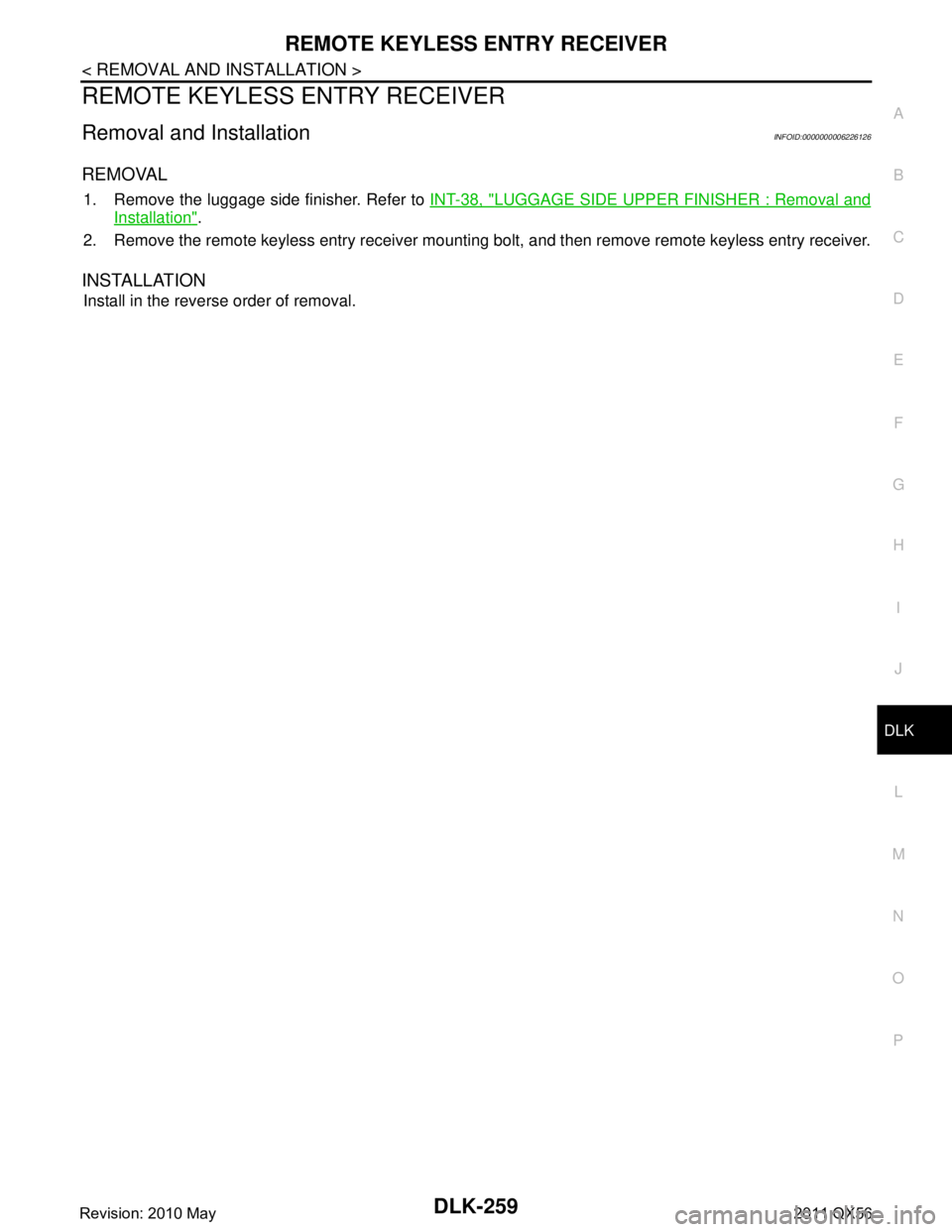
REMOTE KEYLESS ENTRY RECEIVER
Removal and InstallationINFOID:0000000006226126
REMOVAL
1. Remove the luggage side finisher. Refer to INT-38, "LUGGAGE SIDE UPPER FINISHER : Removal and
Installation".
2. Remove the remote keyless entry receiver mounting bolt, and then remove remote keyless entry receiver.
INSTALLATION
Install in the reverse order of removal.
Revision: 2010 May2011 QX56
Page 2736 of 5598
![INFINITI QX56 2011 Factory Service Manual
EXL-26
< SYSTEM DESCRIPTION >[XENON TYPE]
DIAGNOSIS SYSTEM (BCM)
*: Factory setting
DATA MONITOR
ACTIVE TEST
Service item Setting item Setting
HAZARD ANSWER
BACK Lock Only With locking only
Sets the INFINITI QX56 2011 Factory Service Manual
EXL-26
< SYSTEM DESCRIPTION >[XENON TYPE]
DIAGNOSIS SYSTEM (BCM)
*: Factory setting
DATA MONITOR
ACTIVE TEST
Service item Setting item Setting
HAZARD ANSWER
BACK Lock Only With locking only
Sets the](/manual-img/42/57033/w960_57033-2735.png)
EXL-26
< SYSTEM DESCRIPTION >[XENON TYPE]
DIAGNOSIS SYSTEM (BCM)
*: Factory setting
DATA MONITOR
ACTIVE TEST
Service item Setting item Setting
HAZARD ANSWER
BACK Lock Only With locking only
Sets the hazard warning lamp answer back function
when the door is lock/unlock with the request switch or
the key fob.
Unlk Only With unlocking only
Lock&Unlk
*With locking/unlocking
Off Without the function
Monitor item [Unit] Description
REQ SW-DR
[On/Off] The switch status input from the request switch (driver side)
REQ SW-AS
[On/Off] The switch status input from the request switch (passenger side)
PUSH SW
[On/Off] The switch status input from the push-button ignition switch
TURN SIGNAL R
[On/Off] Each switch status that BCM detects from the combination switch reading function
TURN SIGNAL L
[On/Off]
HAZARD SW
[On/Off] The switch status input from the hazard switch
RKE-LOCK
[On/Off] Lock signal status received from the remote keyless entry receiver
RKE-UNLOCK
[On/Off] Unlock signal status received from the remote keyless entry receiver
RKE-PANIC
[On/Off] Panic alarm signal status received from the remote keyless entry receiver
Test item Operation Description
FLASHER RH Outputs the voltage to blink the right side turn signal lamps.
LH Outputs the voltage to blink the left side turn signal lamps.
Off Stops the voltage to turn the turn signal lamps OFF.
Revision: 2010 May2011 QX56
Page 3271 of 5598
INL-4
< SYSTEM DESCRIPTION >
COMPONENT PARTS
SYSTEM DESCRIPTION
COMPONENT PARTS
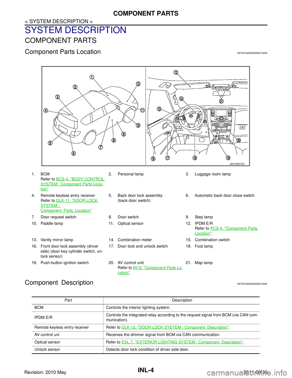
Component Parts LocationINFOID:0000000006216048
Component DescriptionINFOID:0000000006216049
1. BCMRefer to BCS-4, "
BODY CONTROL
SYSTEM : Componen t Parts Loca-
tion"
2. Personal lamp 3. Luggage room lamp
4. Remote keyless entry receiver Refer to DLK-11, "
DOOR LOCK
SYSTEM :
ComponentPartsLocation"
5. Back door lock assembly
(back door switch) 6. Automatic back door close switch
7. Door request switch 8. Door switch 9. Step lamp
10. Paddle lamp 11. Optical sensor 12. IPDM E/R Refer to PCS-4, "
Component Parts
Location"
13. Vanity mirror lamp 14. Combination meter 15. Combination switch
16. Front door lock assembly (driver
side) (door key cylinder switch, un-
lock sensor) 17. Door lock and unlock switch 18. Foot lamp
19. Push-button ignition switch 20. AV control unit Refer to AV- 9 , "
Component Parts Lo-
cation"
21. Map lamp
JMLIA0837ZZ
Part Description
BCM Controls the interior lighting system.
IPDM E/R Controls the integrated relay according to the request signal from BCM (via CAN com-
munication).
Remote keyless entry receiver Refer to DLK-12, "
DOOR LOCK SYSTEM : ComponentDescription".
AV control uni Receives the dimmer signal from BCM via CAN communication.
Optical sensor Refer to EXL-7, "
EXTERIOR LIGHTING SYSTEM : ComponentDescription".
Unlock sensor Detects door lock condition of driver side door.
Revision: 2010 May2011 QX56
Page 3274 of 5598
SYSTEMINL-7
< SYSTEM DESCRIPTION >
C
DE
F
G H
I
J
K
M A
B
INL
N
O P
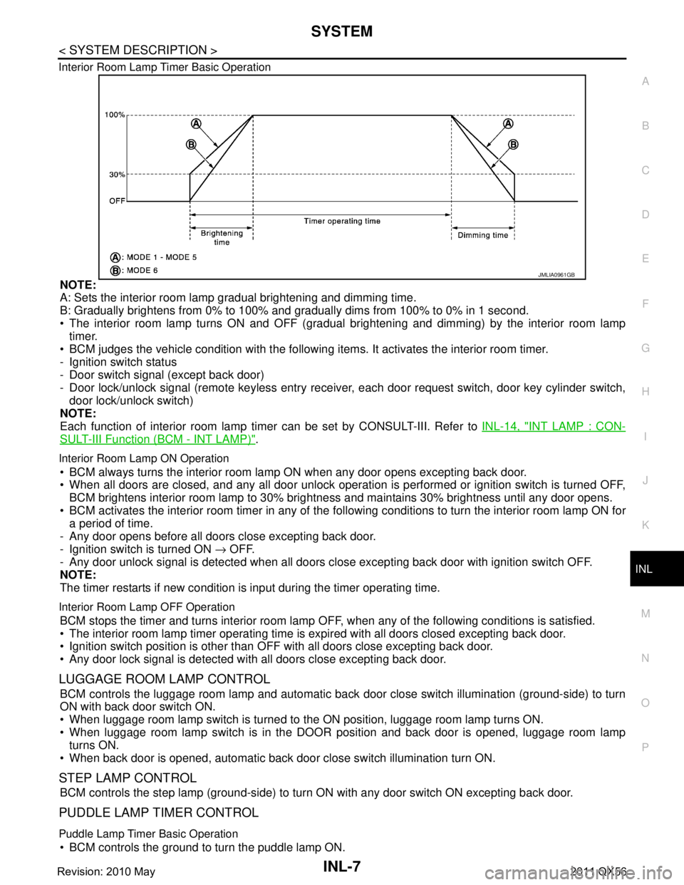
Interior Room Lamp Timer Basic Operation
NOTE:
A: Sets the interior room lamp gradual brightening and dimming time.
B: Gradually brightens from 0% to 100% and gradually dims from 100% to 0% in 1 second.
The interior room lamp turns ON and OFF (gradual brightening and dimming) by the interior room lamp
timer.
BCM judges the vehicle condition with the following items. It activates the interior room timer.
- Ignition switch status
- Door switch signal (except back door)
- Door lock/unlock signal (remote keyless entry receiv er, each door request switch, door key cylinder switch,
door lock/unlock switch)
NOTE:
Each function of interior room lamp ti mer can be set by CONSULT-III. Refer to INL-14, "
INT LAMP : CON-
SULT-III Function (BCM - INT LAMP)".
Interior Room Lamp ON Operation
BCM always turns the interior room lamp ON when any door opens excepting back door.
When all doors are closed, and any all door unlock operation is performed or ignition switch is turned OFF,
BCM brightens interior room lamp to 30% bri ghtness and maintains 30% brightness until any door opens.
BCM activates the interior room timer in any of the fo llowing conditions to turn the interior room lamp ON for
a period of time.
- Any door opens before all doors close excepting back door.
- Ignition switch is turned ON → OFF.
- Any door unlock signal is detected when all doors cl ose excepting back door with ignition switch OFF.
NOTE:
The timer restarts if new condition is input during the timer operating time.
Interior Room Lamp OFF Operation
BCM stops the timer and turns interior room lamp OF F, when any of the following conditions is satisfied.
The interior room lamp timer operating time is expired with all doors closed excepting back door.
Ignition switch position is other than O FF with all doors close excepting back door.
Any door lock signal is detected with all doors close excepting back door.
LUGGAGE ROOM LAMP CONTROL
BCM controls the luggage room lamp and automatic back door close switch illumination (ground-side) to turn
ON with back door switch ON.
When luggage room lamp switch is turned to the ON position, luggage room lamp turns ON.
When luggage room lamp switch is in the DOOR position and back door is opened, luggage room lamp turns ON.
When back door is opened, automatic back door close switch illumination turn ON.
STEP LAMP CONTROL
BCM controls the step lamp (ground-side) to turn ON with any door switch ON excepting back door.
PUDDLE LAMP TIMER CONTROL
Puddle Lamp Timer Basic Operation
BCM controls the ground to turn the puddle lamp ON.
JMLIA0961GB
Revision: 2010 May2011 QX56
Page 3275 of 5598

INL-8
< SYSTEM DESCRIPTION >
SYSTEM
The puddle lamp turns ON and OFF by the puddle lamp timer.
BCM judges the vehicle condition with the following items. It activates the puddle lamp timer.
- Ignition switch status
- Door switch signal (except back door)
- Door lock/unlock signal (remote keyless entry receiver, each door request switch)
- Driver side door lock status
Puddle Lamp ON Operation
BCM activates the puddle lamp timer in any of the following conditions to turn the puddle lamp ON for a period
of time.
Any door opens excepting back door.
Any door opens before all doors close excepting back door.
Ignition switch is turned ON → OFF.
Door unlock signal by remote keyless entry rece iver or each door request switch is detected.
Driver side door is locked*.
NOTE:
The timer restarts if new condition is input during the timer operating time.
Puddle Lamp OFF Operation
BCM stops the timer and turns puddle lamp OFF, when any of the following conditions are satisfied.
The puddle lamp timer operating time is expired.
The interior room lamp OFF conditions.
The interior room lamp timer operating time is expired.
PUSH-BUTTON IGNITION SWITCH ILLUMINATION CONTROL
Push-button Ignition Switch Illumination Basic Operation
BCM controls the ON/OFF status of push-button igni tion switch illumination according to vehicle status.
BCM provides the push-button ignition switch illumi nation control signal and the ground to turn the push-but-
ton ignition switch illumination ON.
BCM cuts the ground supply while each illumination (tai l lamp) is ON. BCM switches to the ground control
according to the meter illumination control function. Refer to MWI-16, "
METER ILLUMINATION CONTROL :
System Description".
Heart Beat Operation
BCM repeats brightening and dimming operation of push-button ignition switch illumination when any of the
following conditions are satisfied.
Welcome light function operates.
When ignition switch is OFF and any of the following conditions are satisfied.
- Driver side door changes from closed to open
- Driver side door changes from locked to unlocked
- Intelligent Key ID comparison is OK and driver side door changes from open to closed
- ID comparison by Intelligent Key transponder is OK
Illumination ON Operation
When ignition switch is not OFF or tail lamp turns ON, push-button ignition switch illumination turns ON.
Dimming Operation
When tail lamp turns OFF and ignition switch is turned OFF, push-button ignition switch illumination dims to
50% brightness.
Illumination OFF Operation
Push-button ignition switch illumination turns OFF when ignition switch turns OFF and tail lamp turns from ON
to OFF, while push-button ignition switch illumination is in ON status.
When push-button ignition switch illumination is at 50% brightness or in heartbeat status, and any of the fol-
lowing conditions are satisfied, push-butt on ignition switch illumination turns OFF.
15 seconds after start of heartbeat operation.
When welcome light function is not operating and any on the following conditions is satisfied.
- Driver side door is closed
- Driver side door is locked
- Intelligent Key ID comparison is NG
- Comparison of Intelligent Key ID by transponder is NG
INTERIOR ROOM LAMP BATTERY SAVER SYSTEM
Revision: 2010 May2011 QX56