2011 INFINITI QX56 Ignition coil
[x] Cancel search: Ignition coilPage 2595 of 5598
ROCKER COVEREM-33
< REMOVAL AND INSTALLATION >
C
DE
F
G H
I
J
K L
M A
EM
NP
O
ROCKER COVER
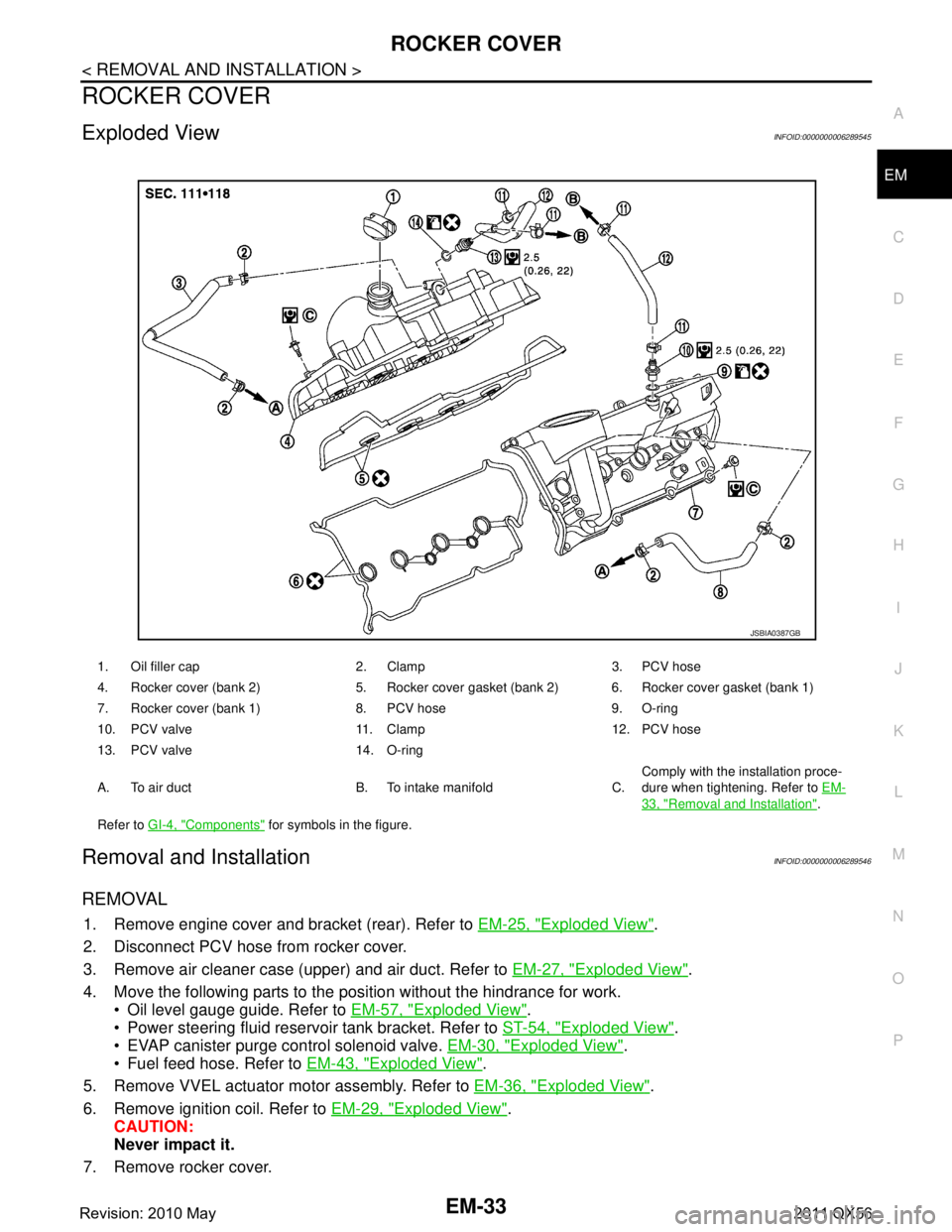
Exploded ViewINFOID:0000000006289545
Removal and InstallationINFOID:0000000006289546
REMOVAL
1. Remove engine cover and bracket (rear). Refer to
EM-25, "Exploded View".
2. Disconnect PCV hose from rocker cover.
3. Remove air cleaner case (upper) and air duct. Refer to EM-27, "
Exploded View".
4. Move the following parts to the position without the hindrance for work. Oil level gauge guide. Refer to EM-57, "
Exploded View".
Power steering fluid reservoir tank bracket. Refer to ST-54, "
Exploded View".
EVAP canister purge control solenoid valve. EM-30, "
Exploded View".
Fuel feed hose. Refer to EM-43, "
Exploded View".
5. Remove VVEL actuator motor assembly. Refer to EM-36, "
Exploded View".
6. Remove ignition coil. Refer to EM-29, "
Exploded View".
CAUTION:
Never impact it.
7. Remove rocker cover.
1. Oil filler cap 2. Clamp 3. PCV hose
4. Rocker cover (bank 2) 5. Rocker cover gasket (bank 2) 6. Rocker cover gasket (bank 1)
7. Rocker cover (bank 1) 8. PCV hose 9. O-ring
10. PCV valve 11. Clamp 12. PCV hose
13. PCV valve 14. O-ring
A. To air duct B. To intake manifold C. Comply with the installation proce-
dure when tightening. Refer to
EM-
33, "Removal and Installation".
Refer to GI-4, "
Components" for symbols in the figure.
JSBIA0387GB
Revision: 2010 May2011 QX56
Page 2597 of 5598
ROCKER COVEREM-35
< REMOVAL AND INSTALLATION >
C
DE
F
G H
I
J
K L
M A
EM
NP
O
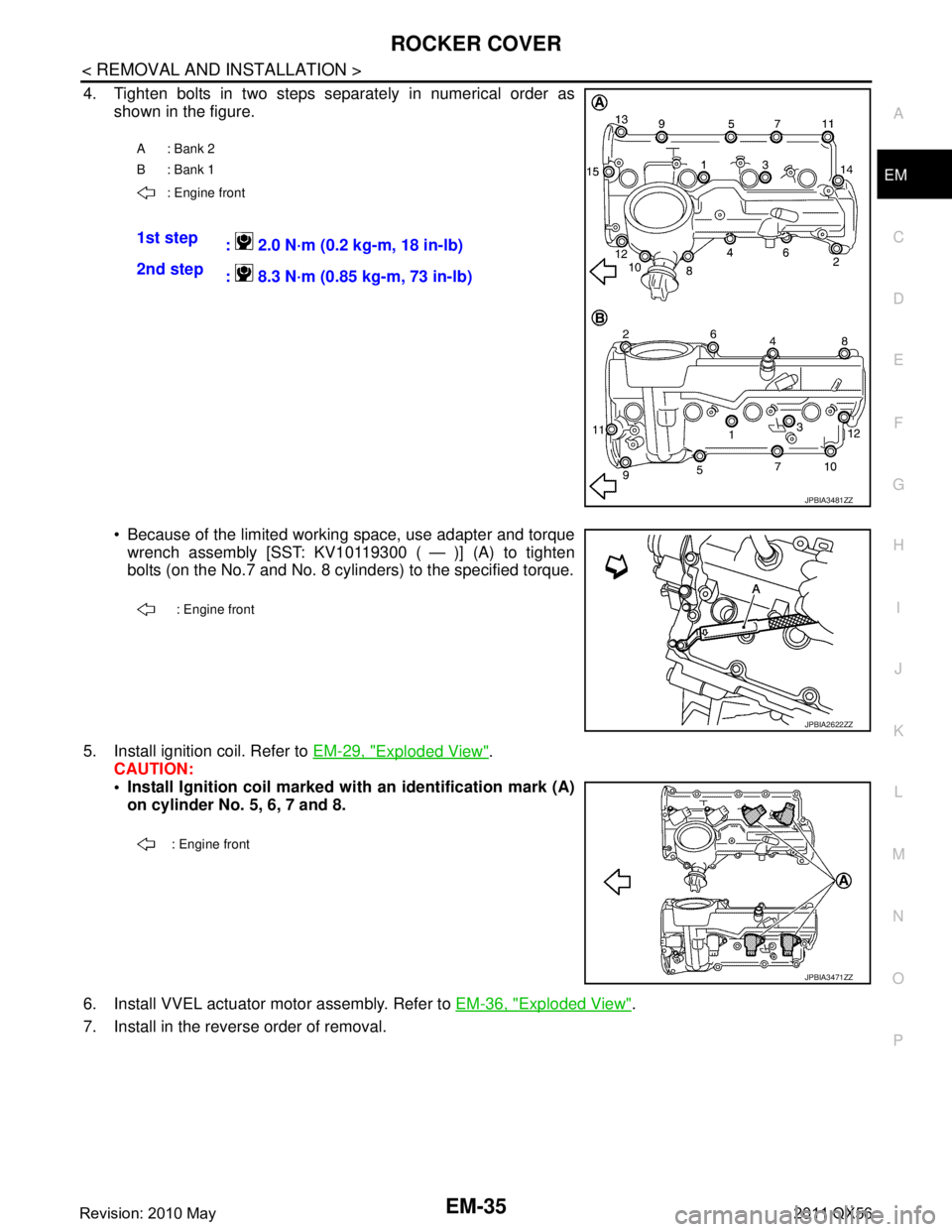
4. Tighten bolts in two steps separately in numerical order as
shown in the figure.
Because of the limited working space, use adapter and torquewrench assembly [SST: KV10119300 ( — )] (A) to tighten
bolts (on the No.7 and No. 8 cylinders) to the specified torque.
5. Install ignition coil. Refer to EM-29, "
Exploded View".
CAUTION:
Install Ignition coil marked with an identification mark (A)
on cylinder No. 5, 6, 7 and 8.
6. Install VVEL actuator motor assembly. Refer to EM-36, "
Exploded View".
7. Install in the reverse order of removal.
A: Bank 2
B: Bank 1
: Engine front
1st step : 2.0 N·m (0.2 kg-m, 18 in-lb)
2nd step : 8.3 N·m (0.85 kg-m, 73 in-lb)
JPBIA3481ZZ
: Engine front
JPBIA2622ZZ
: Engine front
JPBIA3471ZZ
Revision: 2010 May2011 QX56
Page 2646 of 5598
EM-84
< REMOVAL AND INSTALLATION >
CAMSHAFT
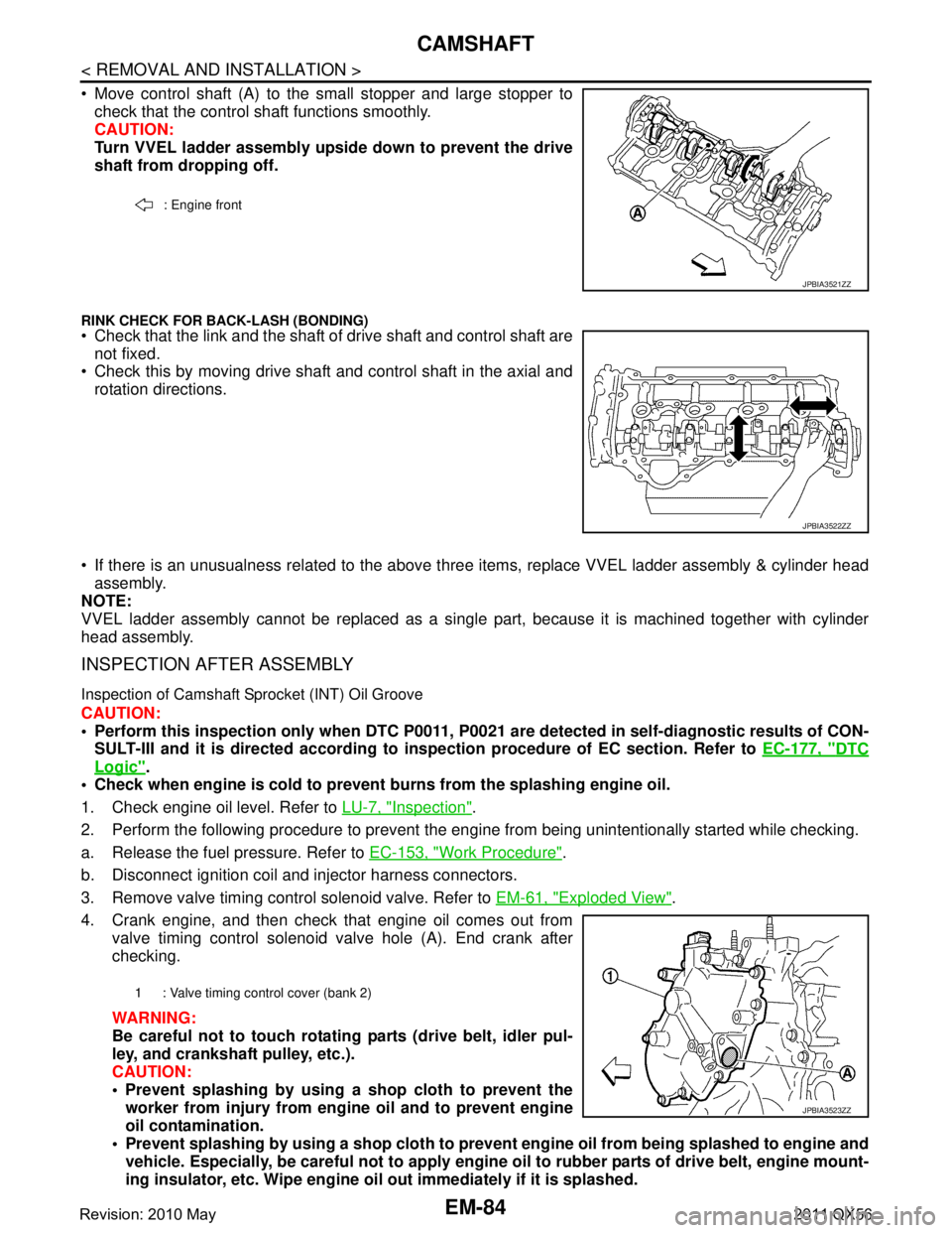
Move control shaft (A) to the small stopper and large stopper tocheck that the control shaft functions smoothly.
CAUTION:
Turn VVEL ladder assembly upside down to prevent the drive
shaft from dropping off.
RINK CHECK FOR BACK-LASH (BONDING) Check that the link and the shaft of drive shaft and control shaft are
not fixed.
Check this by moving drive shaft and control shaft in the axial and
rotation directions.
If there is an unusualness related to the above three items, replace VVEL ladder assembly & cylinder head
assembly.
NOTE:
VVEL ladder assembly cannot be replaced as a singl e part, because it is machined together with cylinder
head assembly.
INSPECTION AFTER ASSEMBLY
Inspection of Camshaft Sprocket (INT) Oil Groove
CAUTION:
Perform this inspection only when DTC P0011, P 0021 are detected in self-diagnostic results of CON-
SULT-III and it is directed according to inspection procedure of EC section. Refer to EC-177, "
DTC
Logic".
Check when engine is cold to prevent burns from the splashing engine oil.
1. Check engine oil level. Refer to LU-7, "
Inspection".
2. Perform the following procedure to prevent the engine from being unintentionally started while checking.
a. Release the fuel pressure. Refer to EC-153, "
Work Procedure".
b. Disconnect ignition coil and injector harness connectors.
3. Remove valve timing control solenoid valve. Refer to EM-61, "
Exploded View".
4. Crank engine, and then check that engine oil comes out from valve timing control solenoid valve hole (A). End crank after
checking.
WARNING:
Be careful not to touch rotati ng parts (drive belt, idler pul-
ley, and crankshaft pulley, etc.).
CAUTION:
Prevent splashing by using a shop cloth to prevent the worker from injury from en gine oil and to prevent engine
oil contamination.
Prevent splashing by using a shop cloth to prevent engine oil from being splashed to engine and
vehicle. Especially, be careful not to apply engine oil to rubber parts of drive belt, engine mount-
ing insulator, etc. Wipe engine oil out immediately if it is splashed.
: Engine front
JPBIA3521ZZ
JPBIA3522ZZ
1 : Valve timing control cover (bank 2)
JPBIA3523ZZ
Revision: 2010 May2011 QX56
Page 2665 of 5598

ENGINE STAND SETTINGEM-103
< UNIT DISASSEMBLY AND ASSEMBLY >
C
DE
F
G H
I
J
K L
M A
EM
NP
O
UNIT DISASSEMBLY AND ASSEMBLY
ENGINE STAND SETTING
SettingINFOID:0000000006289579
NOTE:
Explained here is how to disassemble with engine stand s
upporting transmission surface. When using a differ-
ent type of engine stand, note the difference in the steps, etc.
1. Remove the engine assembly from the vehicle. Refer to EM-98, "
Exploded View".
2. Remove crankshaft pulley. Refer to EM-96, "
FRONT OIL SEAL : Removal and Installation".
NOTE:
The drive plate is fixed with a ring gear stopper [SST: KV10119200 (J-49277)]. Loosen the crankshaft pul-
ley mounting bolts before installing the engine stand.
3. Remove the parts that may restrict installation of engine to a widely used engine stand. Fix crankshaft with a ring gear stopper [SST: KV10119200 (J-49277)]. Loosen drive plate mounting bolt
with power tool.
Check for deformation or damage of drive plate. Refer to EM-115, "
Inspection".
NOTE:
The procedure is described assuming that you us e a widely used engine stand holding the surface, to
which transmission is installed.
4. Remove pilot converter using the pilot bushing puller (commercial service tool), if necessary.
5. Lift the engine with hoist to inst all it onto the widely used engine stand.
CAUTION:
Use an engine stand that has a load capacity [240 kg (529 lb) or more] large enough for supporting
the engine weight.
If the load capacity of the stand is not adequate, remove the following parts beforehand to reduce the potential risk of overturning the stand.
- Remove intake manifold. Refer to EM-30, "
Exploded View".
- Remove fuel injector and fuel tube assembly. Refer to EM-48, "
Exploded View".
- Remove ignition coil. Refer to EM-29, "
Exploded View".
- Remove rocker cover. Refer to EM-33, "
Exploded View".
- Remove exhaust manifold. Refer to EM-40, "
Exploded View".
- Other removable brackets. NOTE:
The figure shows an example of widely used engine stand (A)
that can hold mating surface of transmission with drive plate
removed.
CAUTION:
Before removing the hang ing chains, check the engine
stand is stable and there is no risk of overturning.
6. Drain engine oil. Refer to LU-8, "
Draining".
JPBIA0190ZZ
Revision: 2010 May2011 QX56
Page 2667 of 5598
ENGINE UNITEM-105
< UNIT DISASSEMBLY AND ASSEMBLY >
C
DE
F
G H
I
J
K L
M A
EM
NP
O
ENGINE UNIT
DisassemblyINFOID:0000000006289580
1. Remove intake manifold. Refer to
EM-30, "Exploded View".
2. Remove exhaust manifold. Refer to EM-40, "
Exploded View".
3. Remove oil pan (lower). Refer to EM-54, "
Exploded View".
4. Remove ignition coil and spark plug. Refer to EM-23, "
Exploded View".
5. Remove rocker cover. Refer to EM-33, "
Exploded View".
6. Remove timing chain. Refer to EM-61, "
Exploded View".
7. Remove exhaust camshaft and VVEL ladder assembly. Refer to EM-74, "
Exploded View".
8. Remove cylinder head. Refer to EM-86, "
Exploded View".
AssemblyINFOID:0000000006289581
Assemble in the reverse order of disassembly.
Revision: 2010 May2011 QX56
Page 3689 of 5598
ENGINE MAINTENANCEMA-19
< PERIODIC MAINTENANCE >
C
DE
F
G H
I
J
K L
M B
MA
N
O A
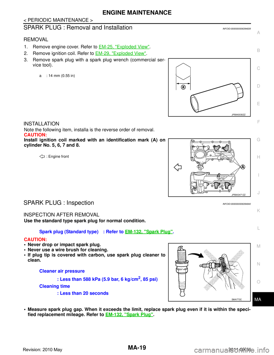
SPARK PLUG : Removal and InstallationINFOID:0000000006394839
REMOVAL
1. Remove engine cover. Refer to
EM-25, "Exploded View".
2. Remove ignition coil. Refer to EM-29, "
Exploded View".
3. Remove spark plug with a spark plug wrench (commercial ser- vice tool).
INSTALLATION
Note the following item, installa is the reverse order of removal.
CAUTION:
Install ignition coil marked wi th an identification mark (A) on
cylinder No. 5, 6, 7 and 8.
SPARK PLUG : InspectionINFOID:0000000006394840
INSPECTION AFTER REMOVAL
Use the standard type spark plug for normal condition.
CAUTION:
Never drop or impact spark plug.
Never use a wire brush for cleaning.
If plug tip is covered with carbon, use spark plug cleaner to
clean.
Measure spark plug gap. When it exceeds the limit, replace spark plug even if it is within the speci-
fied replacement mileage. Refer to EM-132, "
Spark Plug".
a : 14 mm (0.55 in)
JPBIA0030ZZ
: Engine front
JPBIA3471ZZ
Spark plug (Standard type) : Refer to EM-132, "Spark Plug".
Cleaner air pressure : Less than 588 kPa (5.9 bar, 6 kg/cm
2, 85 psi)
Cleaning time
: Less than 20 seconds
SMA773C
Revision: 2010 May2011 QX56
Page 3848 of 5598
![INFINITI QX56 2011 Factory Service Manual
PCS
SYSTEMPCS-7
< SYSTEM DESCRIPTION > [IPDM E/R]
C
D
E
F
G H
I
J
K L
B A
O P
N
IGNITION RELAY MALFUNCTION DETECTION FUNCTION
IPDM E/R monitors the voltage at the contact circuit and
excitation co INFINITI QX56 2011 Factory Service Manual
PCS
SYSTEMPCS-7
< SYSTEM DESCRIPTION > [IPDM E/R]
C
D
E
F
G H
I
J
K L
B A
O P
N
IGNITION RELAY MALFUNCTION DETECTION FUNCTION
IPDM E/R monitors the voltage at the contact circuit and
excitation co](/manual-img/42/57033/w960_57033-3847.png)
PCS
SYSTEMPCS-7
< SYSTEM DESCRIPTION > [IPDM E/R]
C
D
E
F
G H
I
J
K L
B A
O P
N
IGNITION RELAY MALFUNCTION DETECTION FUNCTION
IPDM E/R monitors the voltage at the contact circuit and
excitation coil circuit of the ignition relay inside it.
IPDM E/R judges the ignition relay error if the volt age differs between the contact circuit and the excitation
coil circuit.
If the ignition relay cannot turn OFF due to contact seizure, it activates the tail lamp relay for 10 minutes to alert the user to the ignition relay malfunc tion when the ignition switch is turned OFF.
FRONT WIPER PROTECTION FUNCTION
IPDM E/R detects front wiper stop position by a front wiper stop position signal.
When a front wiper stop position signal is in the conditi ons listed below, IPDM E/R stops power supply to wiper
after repeating a front wiper 10 seconds activation and 20 seconds stop.
NOTE:
This operation status can be confirmed on the IPDM E/ R “Data Monitor” that displays “BLOCK” for the item
“WIP PROT” while the wiper is stopped.
STARTER MOTOR PROTECTION FUNCTION
IPDM E/R turns OFF the starter control relay to protect the starter motor when the starter control relay remains
active for 90 seconds.
POWER CONTROL SYSTEM
Control part Fail-safe operation
Headlamp Turns ON the headlamp low relay when the ignition switch is turned ON
Turns OFF the headlamp low relay when the ignition switch is turned OFF
Headlamp high relay OFF
Parking lamp
License plate lamp
Illumination
Tail lamp Turns ON the tail lamp relay when the ignition switch is turned ON
Turns OFF the tail lamp relay when the ignition switch is turned OFF
Front wiper motor The status just before activation of fail-safe control is maintained until the ignition switch is
turned OFF while the front wiper is operating at LO or HI speed.
The wiper is operated at LO speed until the ignition switch is turned OFF if the fail-safe con- trol is activated while the front wiper is set in the INT mode and the front wiper motor is op-
erating.
Return automatically wiper to stop position when ignition switch is turned ON if fail-safe con- trol is activated while front wiper motor is operated and wiper stops in the other position than
stop position.
Front fog lamp Front fog lamp relay OFF
Horn Horn OFF
Ignition relay The status just before activation of fail-safe is maintained.
Starter motor Starter control relay OFF
Steering lock unit Steering lock relay OFF
Voltage judgment IPDM E/R judgment Operation
Ignition relay contact side Ignition relay excitation coil
side
ON ON Ignition relay ON normal —
OFF OFF Ignition relay OFF normal —
ON OFF Ignition relay ON stuck Detects DTC “B2098: IGN RELAY ON”
Turns ON the tail lamp relay for 10 min-
utes
OFF ON Ignition relay OFF stuck Detects DTC “B2099: IGN RELAY OFF”
Ignition switch Front wiper switch Front wiper stop position signal
ON OFF
The front wiper stop position signal (stop position) cannot be input for
10 seconds.
ON The front wiper stop position signal does not change for 10 seconds.
Revision: 2010 May2011 QX56
Page 3863 of 5598
![INFINITI QX56 2011 Factory Service Manual
PCS-22
< ECU DIAGNOSIS INFORMATION >[IPDM E/R]
IPDM E/R
IGNITION RELAY MALFUNCTION DETECTION FUNCTION
IPDM E/R monitors the voltage at the contact circuit and
excitation coil circuit of the igniti INFINITI QX56 2011 Factory Service Manual
PCS-22
< ECU DIAGNOSIS INFORMATION >[IPDM E/R]
IPDM E/R
IGNITION RELAY MALFUNCTION DETECTION FUNCTION
IPDM E/R monitors the voltage at the contact circuit and
excitation coil circuit of the igniti](/manual-img/42/57033/w960_57033-3862.png)
PCS-22
< ECU DIAGNOSIS INFORMATION >[IPDM E/R]
IPDM E/R
IGNITION RELAY MALFUNCTION DETECTION FUNCTION
IPDM E/R monitors the voltage at the contact circuit and
excitation coil circuit of the ignition relay inside it.
IPDM E/R judges the ignition relay error if the volt age differs between the contact circuit and the excitation
coil circuit.
If the ignition relay cannot turn OFF due to contact seiz ure, it activates the tail lamp relay for 10 minutes to
alert the user to the ignition relay malfunction when the ignition switch is turned OFF.
FRONT WIPER PROTECTION FUNCTION
IPDM E/R detects front wiper stop positi on by a front wiper stop position signal.
When a front wiper stop position signal is in the conditi ons listed below, IPDM E/R stops power supply to wiper
after repeating a front wiper 10 seconds activation and 20 seconds stop.
NOTE:
This operation status can be confirmed on the IPDM E/ R “Data Monitor” that displays “BLOCK” for the item
“WIP PROT” while the wiper is stopped.
STARTER MOTOR PROTECTION FUNCTION
IPDM E/R turns OFF the starter control relay to protect the starter motor when the starter control relay remains
active for 90 seconds.
DTC IndexINFOID:0000000006220174
NOTE:
The details of time display are as follows.
- CRNT: A malfunction is detected now.
- PAST: A malfunction was detected in the past.
IGN counter is displayed on FFD (Freeze Frame data).
- The number is 0 when is detected now.
- The number increases like 1 → 2 ··· 38 → 39 after returning to the normal condition whenever IGN OFF →
ON.
- The number is fixed to 39 until the self-diagnosis results are erased if it is over 39.
× : Applicable
Ignition relay The status just before activation of fail-safe is maintained.
Starter motor Starter control relay OFF
Steering lock unit Steering lock relay OFF Control part Fail-safe operation
Voltage judgment
IPDM E/R judgment Operation
Ignition relay contact side Ignition relay excitation coil
side
ON ON Ignition re lay ON normal —
OFF OFF Ignition relay OFF normal —
ON OFF Ignition relay ON stuck Detects DTC “B2098: IGN RELAY ON”
Turns ON the tail lamp relay for 10 min-
utes
OFF ON Ignition relay OFF stuck Detects DTC “B2099: IGN RELAY OFF”
Ignition switch Front wiper switch Front wiper stop position signal
ON OFF
The front wiper stop position signal (stop position) cannot be input for
10 seconds.
ON The front wiper stop position signal does not change for 10 seconds.
CONSULT display Fail-safe Refer to
No DTC is detected.
further testing
may be required. ——
U1000: CAN COMM CIRCUIT ×PCS-28
B2098: IGN RELAY ON ×PCS-29
Revision: 2010 May2011 QX56