2011 INFINITI QX56 door
[x] Cancel search: doorPage 1747 of 5598

SQUEAK AND RATTLE TROUBLE DIAGNOSESDLK-211
< SYMPTOM DIAGNOSIS >
C
DE
F
G H
I
J
L
M A
B
DLK
N
O P
Insulates where slight movement is present. Ideal for instrument panel applications.
SILICONE GREASE
Used in place of UHMW tape that is be visible or does not fit. Will only last a few months.
SILICONE SPRAY
Used when grease cannot be applied.
DUCT TAPE
Used to eliminate movement.
CONFIRM THE REPAIR
Confirm that the cause of a noise is repaired by test driving the vehicle. Operate the vehicle under the same
conditions as when the noise originally occurred. Refer to the notes on the Diagnostic Worksheet.
Inspection ProcedureINFOID:0000000006226060
Refer to Table of Contents for specific component removal and installation information.
INSTRUMENT PANEL
Most incidents are caused by contact and movement between:
1. Cluster lid A and instrument panel
2. Acrylic lens and combination meter housing
3. Instrument panel to front pillar garnish
4. Instrument panel to windshield
5. Instrument panel mounting pins
6. Wiring harnesses behind the combination meter
7. A/C defroster duct and duct joint
These incidents can usually be located by tapping or moving the components to duplicate the noise or by
pressing on the components while driving to stop the noi se. Most of these incidents can be repaired by apply-
ing felt cloth tape or silicon spray (in hard to reach areas). Urethane pads can be used to insulate wiring har-
ness.
CAUTION:
Do not use silicone spray to isolate a squeak or ra ttle. If you saturate the area with silicone, you will
not be able to recheck the repair.
CENTER CONSOLE
Components to pay attention to include:
1. Shifter assembly cover to finisher
2. A/C control unit and cluster lid C
3. Wiring harnesses behind audio and A/C control unit
The instrument panel repair and isolation pr ocedures also apply to the center console.
DOORS
Pay attention to the:
1. Finisher and inner panel making a slapping noise
2. Inside handle escutcheon to door finisher
3. Wiring harnesses tapping
4. Door striker out of alignment causing a popping noise on starts and stops
Tapping or moving the components or pressing on them while driving to duplicate the conditions can isolate
many of these incidents. You can usually insulate the areas with felt cloth tape or insulator foam blocks to
repair the noise.
TRUNK
Trunk noises are often caused by a loose jack or loose items put into the trunk by the owner.
In addition look for:
1. Trunk lid dumpers out of adjustment
2. Trunk lid striker out of adjustment
3. Trunk lid torsion bars knocking together
4. A loose license plate or bracket
Revision: 2010 May2011 QX56
Page 1759 of 5598
FRONT FENDERDLK-223
< REMOVAL AND INSTALLATION >
C
DE
F
G H
I
J
L
M A
B
DLK
N
O P
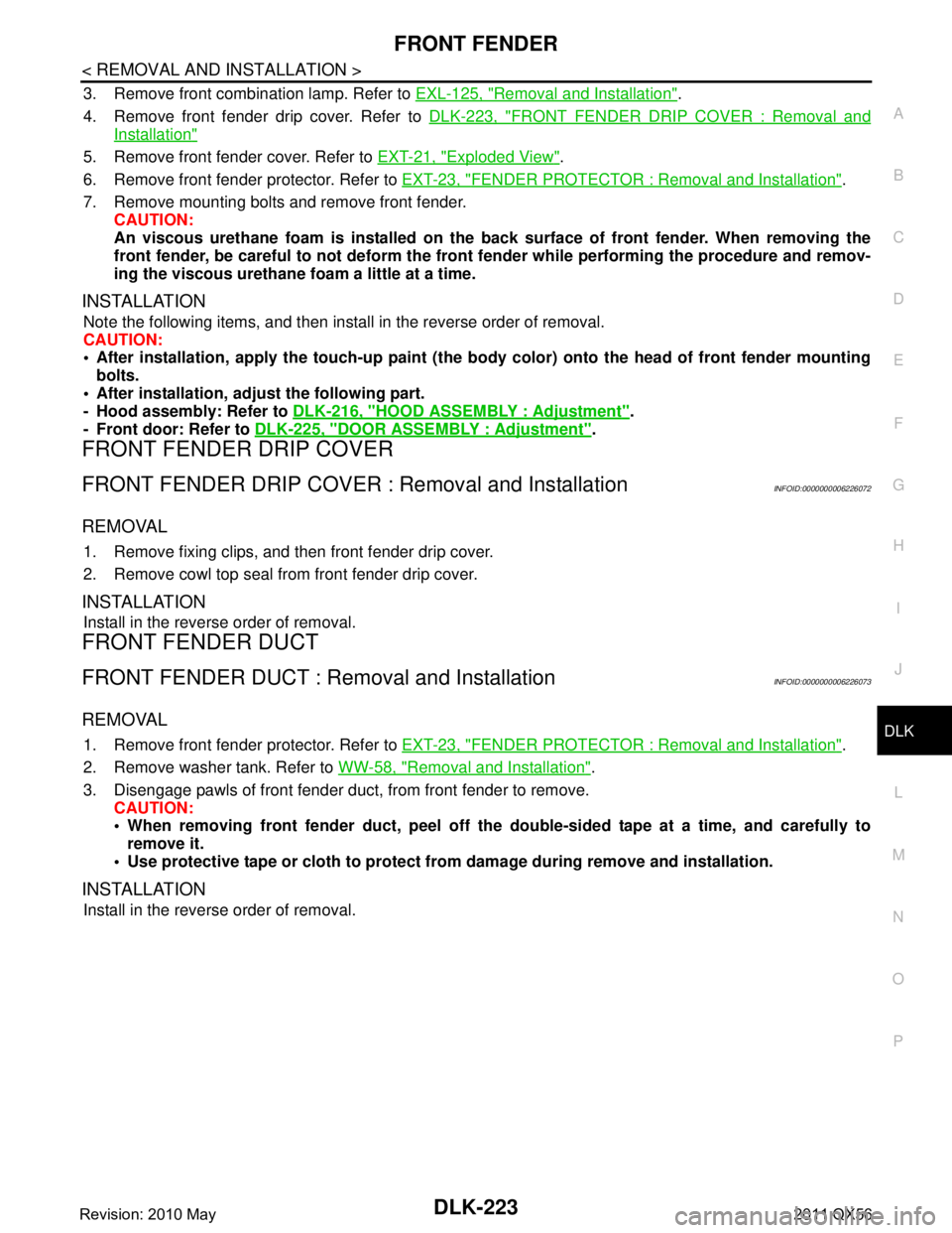
3. Remove front combination lamp. Refer to EXL-125, "Removal and Installation".
4. Remove front fender drip cover. Refer to DLK-223, "
FRONT FENDER DRIP COVER : Removal and
Installation"
5. Remove front fender cover. Refer to EXT-21, "Exploded View".
6. Remove front fender protector. Refer to EXT-23, "
FENDER PROTECTOR : Removal and Installation".
7. Remove mounting bolts and remove front fender. CAUTION:
An viscous urethane foam is installed on the back surface of front fender. When removing the
front fender, be careful to not deform the front fender while performing the procedure and remov-
ing the viscous urethane foam a little at a time.
INSTALLATION
Note the following items, and then install in the reverse order of removal.
CAUTION:
After installation, apply the touc h-up paint (the body color) onto the head of front fender mounting
bolts.
After installation, adju st the following part.
- Hood assembly: Refer to DLK-216, "
HOOD ASSEMBLY : Adjustment".
- Front door: Refer to DLK-225, "
DOOR ASSEMBLY : Adjustment".
FRONT FENDER DRIP COVER
FRONT FENDER DRIP COVER : Removal and InstallationINFOID:0000000006226072
REMOVAL
1. Remove fixing clips, and then front fender drip cover.
2. Remove cowl top seal from front fender drip cover.
INSTALLATION
Install in the reverse order of removal.
FRONT FENDER DUCT
FRONT FENDER DUCT : Removal and InstallationINFOID:0000000006226073
REMOVAL
1. Remove front fender protector. Refer to EXT-23, "FENDER PROTECTOR : Removal and Installation".
2. Remove washer tank. Refer to WW-58, "
Removal and Installation".
3. Disengage pawls of front fender duct, from front fender to remove. CAUTION:
When removing front fender duct, peel off the double-sided tape at a time, and carefully to
remove it.
Use protective tape or cloth to protect from damage during remove and installation.
INSTALLATION
Install in the reverse order of removal.
Revision: 2010 May2011 QX56
Page 1760 of 5598
DLK-224
< REMOVAL AND INSTALLATION >
FRONT DOOR
FRONT DOOR
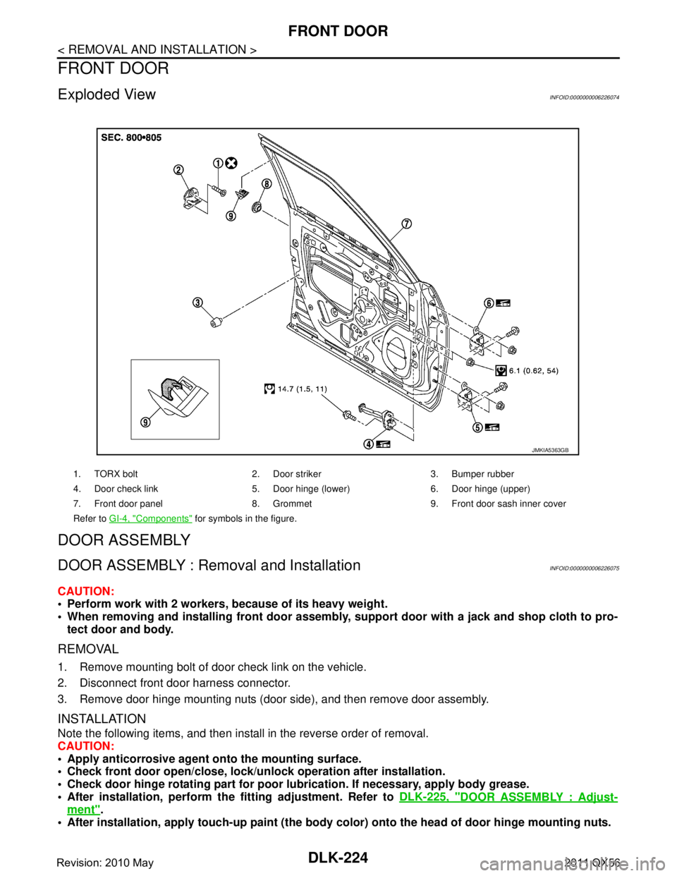
Exploded ViewINFOID:0000000006226074
DOOR ASSEMBLY
DOOR ASSEMBLY : Removal and InstallationINFOID:0000000006226075
CAUTION:
Perform work with 2 workers, because of its heavy weight.
When removing and installing front door assembly, support door with a jack and shop cloth to pro-
tect door and body.
REMOVAL
1. Remove mounting bolt of door check link on the vehicle.
2. Disconnect front door harness connector.
3. Remove door hinge mounting nuts (door side), and then remove door assembly.
INSTALLATION
Note the following items, and then install in the reverse order of removal.
CAUTION:
Apply anticorrosive agent onto the mounting surface.
Check front door open/close, lock/un lock operation after installation.
Check door hinge rotating pa rt for poor lubrication. If necessary, apply body grease.
After installation, perform th e fitting adjustment. Refer to DLK-225, "
DOOR ASSEMBLY : Adjust-
ment".
After installation, apply touch-up paint (the body color) onto the head of door hinge mounting nuts.
1. TORX bolt 2. Door striker 3. Bumper rubber
4. Door check link 5. Door hinge (lower) 6. Door hinge (upper)
7. Front door panel 8. Grommet 9. Front door sash inner cover
Refer to GI-4, "
Components" for symbols in the figure.
JMKIA5363GB
Revision: 2010 May2011 QX56
Page 1761 of 5598
FRONT DOORDLK-225
< REMOVAL AND INSTALLATION >
C
DE
F
G H
I
J
L
M A
B
DLK
N
O P
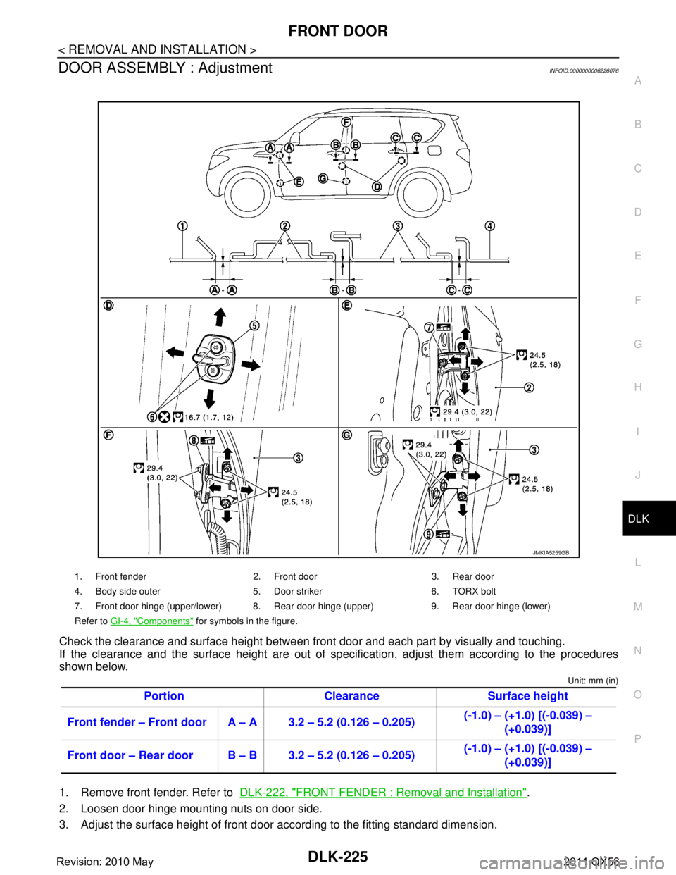
DOOR ASSEMBLY : AdjustmentINFOID:0000000006226076
Check the clearance and surface height between front door and each part by visually and touching.
If the clearance and the surface height are out of spec ification, adjust them according to the procedures
shown below.
Unit: mm (in)
1. Remove front fender. Refer to DLK-222, "FRONT FENDER : Removal and Installation".
2. Loosen door hinge mounting nuts on door side.
3. Adjust the surface height of front door according to the fitting standard dimension.
1. Front fender 2. Front door 3. Rear door
4. Body side outer 5. Door striker 6. TORX bolt
7. Front door hinge (upper/lower) 8. Rear door hinge (upper) 9. Rear door hinge (lower)
Refer to GI-4, "
Components" for symbols in the figure.
Portion Clearance Surface height
Front fender – Front door A – A 3.2 – 5.2 (0.126 – 0.205) (-1.0) – (+1.0) [(-0.039) –
(+0.039)]
Front door – Rear door B – B 3.2 – 5.2 (0.126 – 0.205) (-1.0) – (+1.0) [(-0.039) –
(+0.039)]
JMKIA5259GB
Revision: 2010 May2011 QX56
Page 1762 of 5598
DLK-226
< REMOVAL AND INSTALLATION >
FRONT DOOR
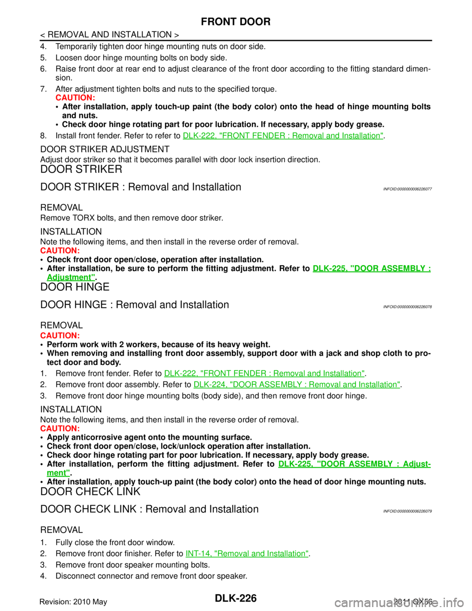
4. Temporarily tighten door hinge mounting nuts on door side.
5. Loosen door hinge mounting bolts on body side.
6. Raise front door at rear end to adjust clearance of the front door according to the fitting standard dimen-
sion.
7. After adjustment tighten bolts and nuts to the specified torque. CAUTION:
After installation, apply touch-up paint (the bo dy color) onto the head of hinge mounting bolts
and nuts.
Check door hinge rotating part for poor lubrication. If necessary, apply body grease.
8. Install front fender. Refer to refer to DLK-222, "
FRONT FENDER : Removal and Installation".
DOOR STRIKER ADJUSTMENT
Adjust door striker so that it becomes parallel with door lock insertion direction.
DOOR STRIKER
DOOR STRIKER : Removal and InstallationINFOID:0000000006226077
REMOVAL
Remove TORX bolts, and then remove door striker.
INSTALLATION
Note the following items, and then install in the reverse order of removal.
CAUTION:
Check front door open/close, operation after installation.
After installation, be sure to perf orm the fitting adjustment. Refer to DLK-225, "
DOOR ASSEMBLY :
Adjustment".
DOOR HINGE
DOOR HINGE : Removal and InstallationINFOID:0000000006226078
REMOVAL
CAUTION:
Perform work with 2 workers, because of its heavy weight.
When removing and installing front door assembly, support door with a jack and shop cloth to pro-
tect door and body.
1. Remove front fender. Refer to DLK-222, "
FRONT FENDER : Removal and Installation".
2. Remove front door assembly. Refer to DLK-224, "
DOOR ASSEMBLY : Removal and Installation".
3. Remove front door hinge mounting bolts (body side), and then remove front door hinge.
INSTALLATION
Note the following items, and then install in the reverse order of removal.
CAUTION:
Apply anticorrosive agent onto the mounting surface.
Check front door open/close, lock/un lock operation after installation.
Check door hinge rotating pa rt for poor lubrication. If necessary, apply body grease.
After installation, perform th e fitting adjustment. Refer to DLK-225, "
DOOR ASSEMBLY : Adjust-
ment".
After installation, apply touch-up paint (the body color) onto the head of door hinge mounting nuts.
DOOR CHECK LINK
DOOR CHECK LINK : Re moval and InstallationINFOID:0000000006226079
REMOVAL
1. Fully close the front door window.
2. Remove front door finisher. Refer to INT-14, "
Removal and Installation".
3. Remove front door speaker mounting bolts.
4. Disconnect connector and remove front door speaker.
Revision: 2010 May2011 QX56
Page 1763 of 5598
FRONT DOORDLK-227
< REMOVAL AND INSTALLATION >
C
DE
F
G H
I
J
L
M A
B
DLK
N
O P
5. Remove mounting bolts, and then front door speaker bracket.
6. Remove mounting bolt of door check link on the vehicle.
7. Remove mounting nuts of door check link on door panel.
8. Take door check link out from the hole of door panel.
INSTALLATION
Note the following item, and then install in the reverse order of removal.
CAUTION:
Check front door open/close ope ration after installation.
Revision: 2010 May2011 QX56
Page 1764 of 5598
DLK-228
< REMOVAL AND INSTALLATION >
REAR DOOR
REAR DOOR
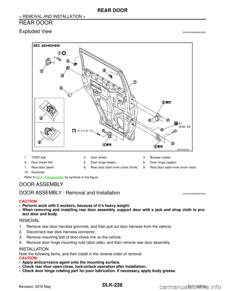
Exploded ViewINFOID:0000000006226080
DOOR ASSEMBLY
DOOR ASSEMBLY : Removal and InstallationINFOID:0000000006226081
CAUTION:
Perform work with 2 workers, because of it’s heavy weight.
When removing and installing rear door assembly, support door with a jack and shop cloth to pro-
tect door and body.
REMOVAL
1. Remove rear door harness grommet, and then pull out door harness from the vehicle.
2. Disconnect rear door harness connector.
3. Remove mounting bolt of door check link on the vehicle.
4. Remove door hinge mounting nuts (door side), and then remove rear door assembly.
INSTALLATION
Note the following items, and then install in the reverse order of removal.
CAUTION:
Apply anticorrosive agent onto the mounting surface.
Check rear door open/close, lock/unl ock operation after installation.
Check door hinge rotating pa rt for poor lubrication. If necessary, apply body grease.
1. TORX bolt 2. Door striker 3. Bumper rubber
4. Door check link 5. Door hinge (lower) 6. Door hinge (upper)
7. Rear door panel 8. Rear door sash inner cove r (front) 9. Rear door sash inner cover (rear)
10. Grommet
Refer to GI-4, "
Components" for symbols in the figure.
JMKIA5364GB
Revision: 2010 May2011 QX56
Page 1765 of 5598
REAR DOORDLK-229
< REMOVAL AND INSTALLATION >
C
DE
F
G H
I
J
L
M A
B
DLK
N
O P
After installation, perform th e fitting adjustment. Refer to DLK-229, "DOOR ASSEMBLY : Adjust-
ment".
After installation, apply touch-up paint (the body color) onto the head of door hinge mounting nuts.
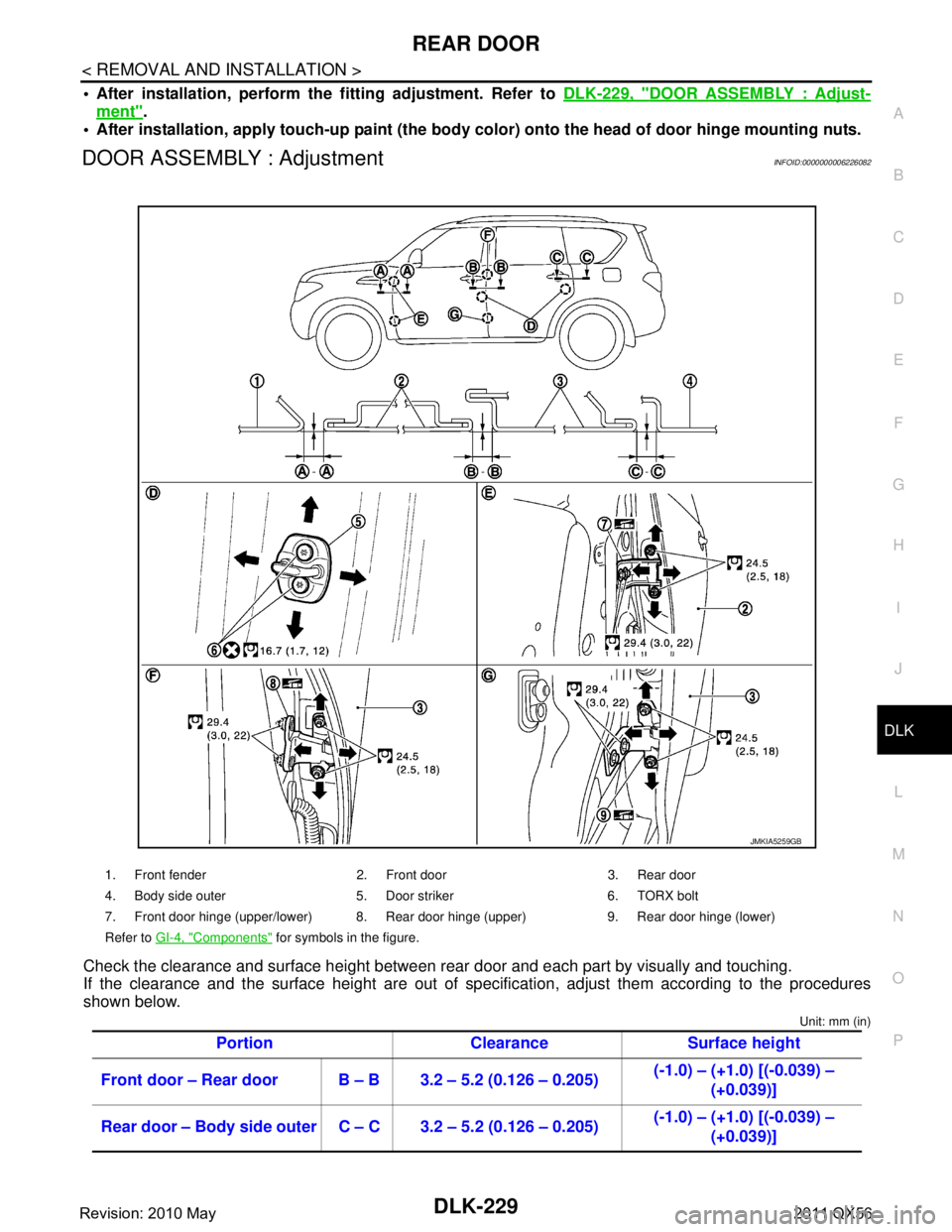
DOOR ASSEMBLY : AdjustmentINFOID:0000000006226082
Check the clearance and surface height between rear door and each part by visually and touching.
If the clearance and the surface height are out of spec ification, adjust them according to the procedures
shown below.
Unit: mm (in)
1. Front fender 2. Front door 3. Rear door
4. Body side outer 5. Door striker 6. TORX bolt
7. Front door hinge (upper/lower) 8. Rear door hinge (upper) 9. Rear door hinge (lower)
Refer to GI-4, "
Components" for symbols in the figure.
Portion Clearance Surface height
Front door – Rear door B – B 3.2 – 5.2 (0.126 – 0.205) (-1.0) – (+1.0) [(-0.039) –
(+0.039)]
Rear door – Body side outer C – C 3.2 – 5.2 (0.126 – 0.205) (-1.0) – (+1.0) [(-0.039) –
(+0.039)]
JMKIA5259GB
Revision: 2010 May2011 QX56