2011 INFINITI QX56 Fuel
[x] Cancel search: FuelPage 2945 of 5598
PRECAUTIONSFSU-3
< PRECAUTION >
C
DF
G H
I
J
K L
M A
B
FSU
N
O P
5. When the repair work is completed, re-connect both battery cables. With the brake pedal released, turn
the push-button ignition switch from ACC position to ON position, then to LOCK position. (The steering
wheel will lock when the push-button ignition switch is turned to LOCK position.)
6. Perform self-diagnosis check of a ll control units using CONSULT-III.
Precaution for Procedure without Cowl Top CoverINFOID:0000000006271994
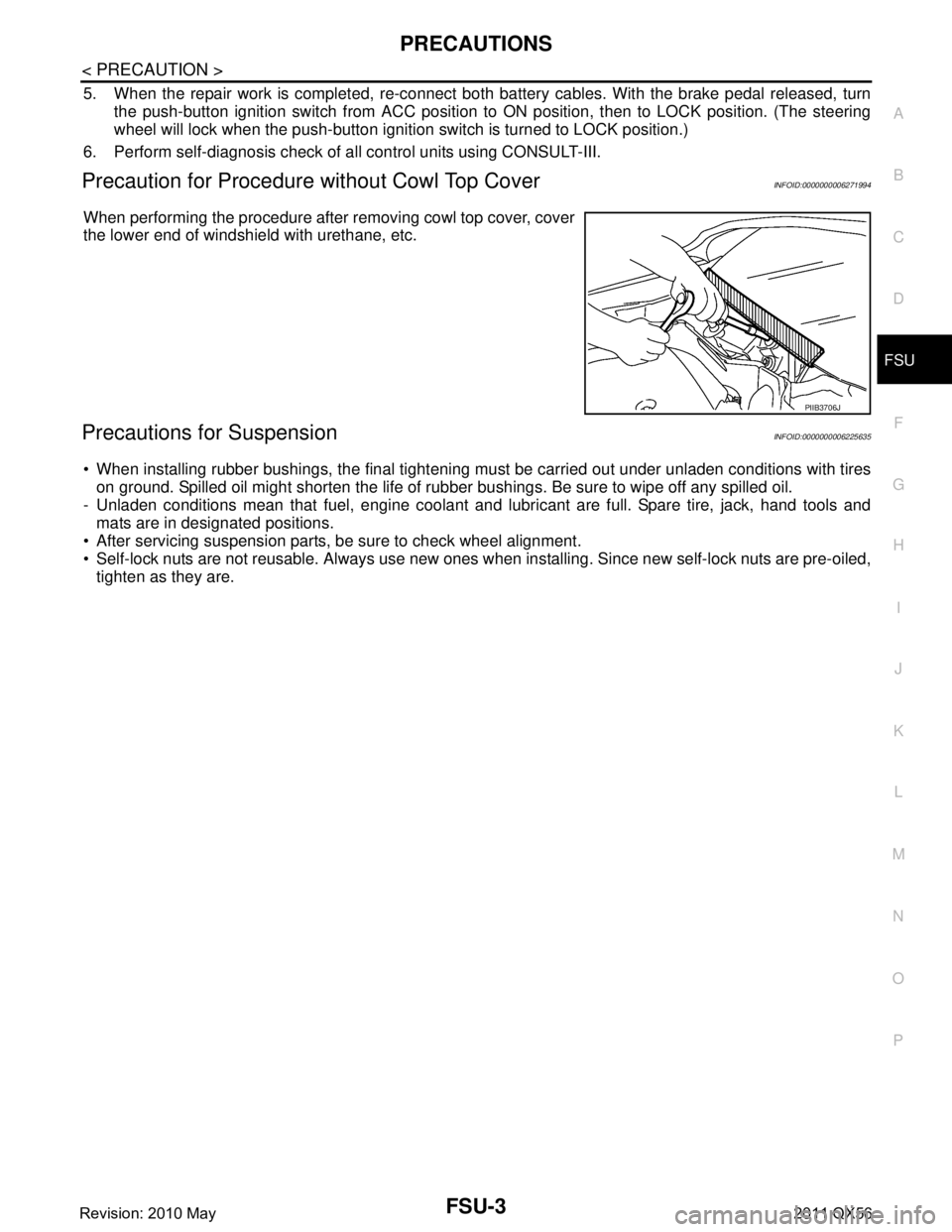
When performing the procedure after removing cowl top cover, cover
the lower end of windshield with urethane, etc.
Precautions for SuspensionINFOID:0000000006225635
When installing rubber bushings, the final tightening mu st be carried out under unladen conditions with tires
on ground. Spilled oil might shorten the life of rubb er bushings. Be sure to wipe off any spilled oil.
- Unladen conditions mean that fuel, engine coolant and l ubricant are full. Spare tire, jack, hand tools and
mats are in designated positions.
After servicing suspension parts, be sure to check wheel alignment.
Self-lock nuts are not reusable. Always use new ones w hen installing. Since new self-lock nuts are pre-oiled,
tighten as they are.
PIIB3706J
Revision: 2010 May2011 QX56
Page 2949 of 5598
WHEEL ALIGNMENTFSU-7
< PERIODIC MAINTENANCE >
C
DF
G H
I
J
K L
M A
B
FSU
N
O P
WHEEL ALIGNMENT
InspectionINFOID:0000000006225640
DESCRIPTION
Measure wheel alignment under unladen conditions.
NOTE:
“Unladen conditions” means that fuel, engine coolant, and lubricant are full. Spare tire, jack, hand tools and
mats are in designated positions.
PRELIMINARY CHECK
Check the following:
Tires for improper air pressure and wear
Road wheels for runout: Refer to WT-64, "
Inspection".
Wheel bearing axial end play: Refer to FA X - 7 , "
Inspection" (2WD), FAX-16, "Inspection" (4WD).
Lower link and upper link ball joint axial end play: Refer to FSU-15, "
Inspection" and FSU-18, "Inspection".
Shock absorber operation.
Each mounting part of axle and suspension for looseness and deformation
Lower link for cracks, deformation and other damage
Vehicle height (posture)
GENERAL INFORMATION AND RECOMMENDATIONS
A four-wheel thrust alignment should be performed.
- This type of alignment is recomm ended for any NISSAN/INFINITI vehicle.
- The four-wheel “thrust” process helps ensure that t he vehicle is properly aligned and the steering wheel is
centered.
- The alignment rack itself should be capable of accepting any NISSAN/INFINITI vehicle.
- The rack should be checked to ensure that it is level.
Make sure the machine is properly calibrated.
- Your alignment equipment should be regularly ca librated in order to give correct information.
- Check with the manufacturer of your specific equi pment for their recommended Service/Calibration Sched-
ule.
ALIGNMENT PROCESS
IMPORTANT:
Use only the alignment specificati ons listed in this Service Manual.
When displaying the alignment settings, many alignment machines use “indicators”: (Green/red, plus or
minus, Go/No Go). Never use these indicators.
- The alignment specifications programmed into your machine that operate these indicators may not be cor-
rect.
- This may result in an ERROR.
Some newer alignment machines are equipped with an optional “Rolling Compensation” method to “com-
pensate” the sensors (alignment targets or head units). Never use this “Rolling Compensation” method.
- Use the “Jacking Compensation Method”. After installi ng the alignment targets or head units, raise the vehi-
cle and rotate the wheels 1/2 turn both ways.
- See Instructions in the alignment machine you're using for more information on this.
AdjustmentINFOID:0000000006225641
CAMBER, CASTER
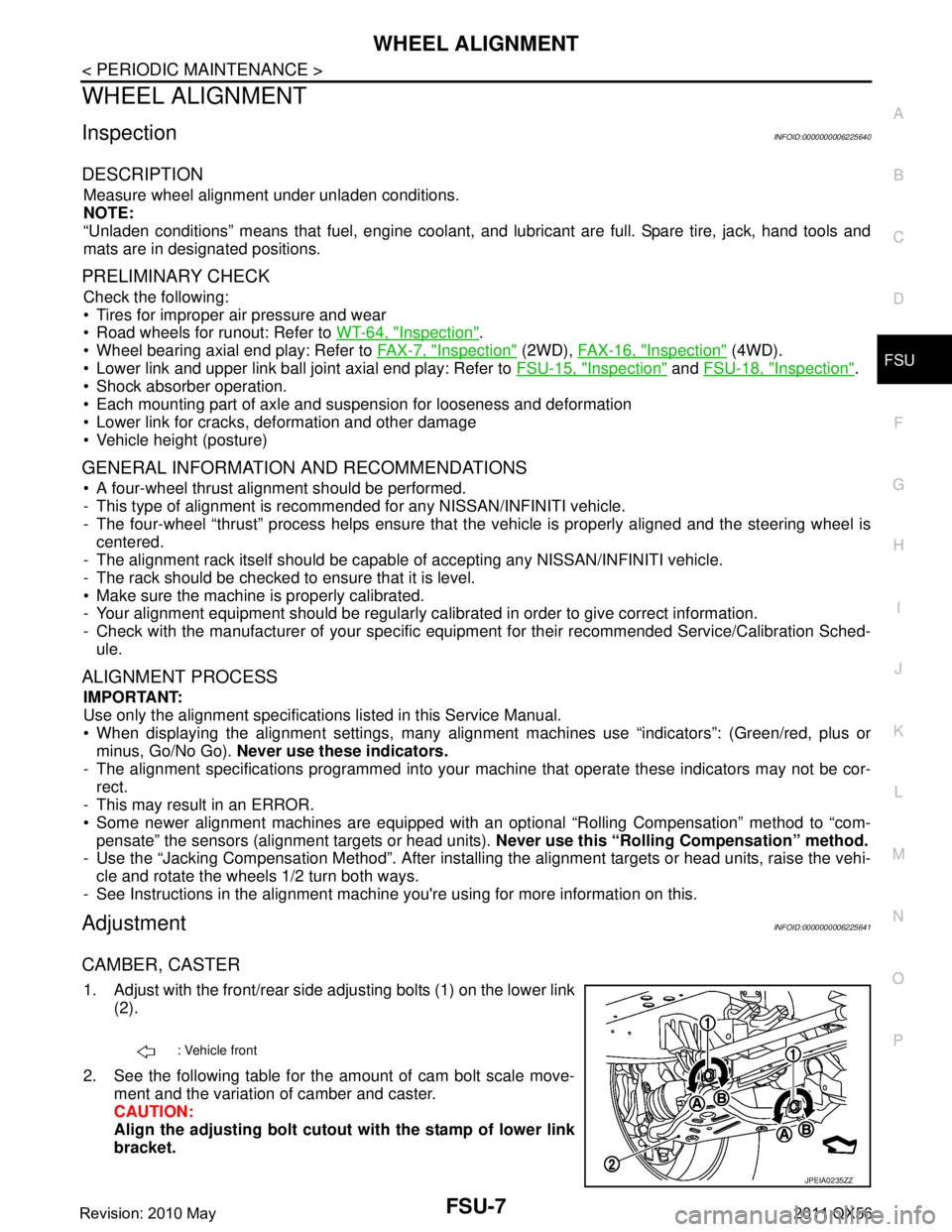
1. Adjust with the front/rear side adjusting bolts (1) on the lower link
(2).
2. See the following table for the amount of cam bolt scale move- ment and the variation of camber and caster.
CAUTION:
Align the adjusting bolt cutout with the stamp of lower link
bracket.
: Vehicle front
JPEIA0235ZZ
Revision: 2010 May2011 QX56
Page 2963 of 5598
SERVICE DATA AND SPECIFICATIONS (SDS)
FSU-21
< SERVICE DATA AND SPECIFICATIONS (SDS)
C
D F
G H
I
J
K L
M A
B
FSU
N
O P
SERVICE DATA AND SPECIFICATIONS (SDS)
SERVICE DATA AND SPECIFICATIONS (SDS)
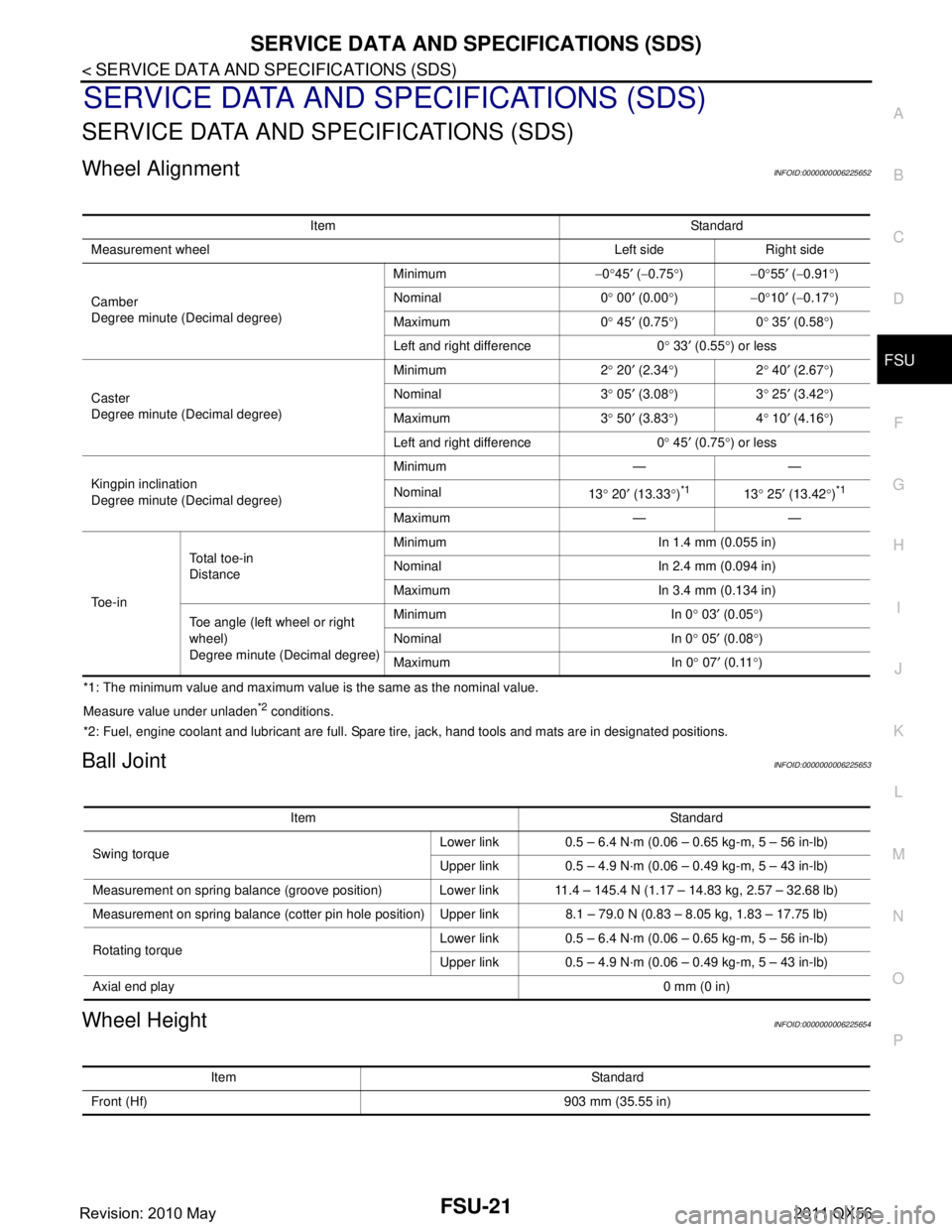
Wheel AlignmentINFOID:0000000006225652
*1: The minimum value and maximum value is the same as the nominal value.
Measure value under unladen
*2 conditions.
*2: Fuel, engine coolant and lubricant are full. Spare tire, jack, hand tools and mats are in designated positions.
Ball JointINFOID:0000000006225653
Wheel HeightINFOID:0000000006225654
Item Standard
Measurement wheel Left side Right side
Camber
Degree minute (Decimal degree) Minimum
−0 °45 ′ ( −0.75 °) −0°55 ′ ( −0.91 °)
Nominal 0 ° 00 ′ (0.00 °) −0°10 ′ ( −0.17 °)
Maximum 0 ° 45 ′ (0.75 °)0 ° 35 ′ (0.58 °)
Left and right difference 0 ° 33 ′ (0.55 °) or less
Caster
Degree minute (Decimal degree) Minimum 2
° 20 ′ (2.34 °)2 ° 40 ′ (2.67 °)
Nominal 3 ° 05 ′ (3.08 °)3 ° 25 ′ (3.42 °)
Maximum 3 ° 50 ′ (3.83 °)4 ° 10 ′ (4.16
° )
Left and right difference 0 ° 45 ′ (0.75 °) or less
Kingpin inclination
Degree minute (Decimal degree) Minimum — —
Nominal
13° 20 ′ (13.33 °)
*113 ° 25 ′ (13.42 °)*1
Maximum — —
To e - i n To t a l t o e - i n
Distance
Minimum In 1.4 mm (0.055 in)
Nominal In 2.4 mm (0.094 in)
Maximum In 3.4 mm (0.134 in)
Toe angle (left wheel or right
wheel)
Degree minute (Decimal degree) Minimum In 0
° 03 ′ (0.05 °)
Nominal In 0 ° 05 ′ (0.08 °)
Maximum In 0 ° 07 ′ (0.11 °)
Item Standard
Swing torque Lower link 0.5 – 6.4 N·m (0.06 – 0.65 kg-m, 5 – 56 in-lb)
Upper link 0.5 – 4.9 N·m (0.06 – 0.49 kg-m, 5 – 43 in-lb)
Measurement on spring balance (groove position) Lower link 11.4 – 145.4 N (1.17 – 14.83 kg, 2.57 – 32.68 lb)
Measurement on spring balance (cotter pin hole position) Upper link 8.1 – 79.0 N (0.83 – 8.05 kg, 1.83 – 17.75 lb)
Rotating torque Lower link 0.5 – 6.4 N·m (0.06 – 0.65 kg-m, 5 – 56 in-lb)
Upper link 0.5 – 4.9 N·m (0.06 – 0.49 kg-m, 5 – 43 in-lb)
Axial end play 0 mm (0 in)
Item Standard
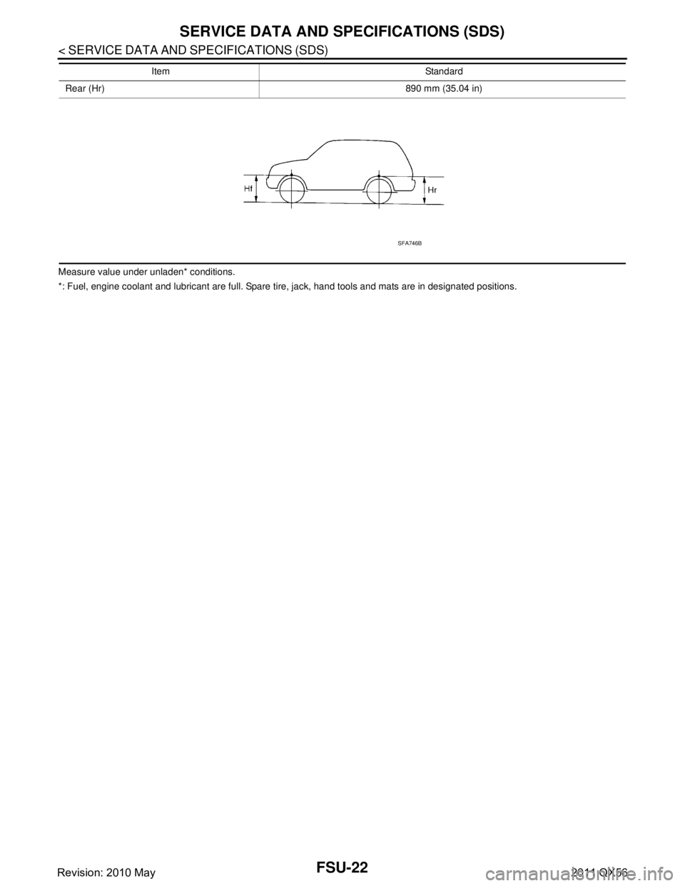
Front (Hf) 903 mm (35.55 in)
Revision: 2010 May2011 QX56
Page 2964 of 5598
FSU-22
< SERVICE DATA AND SPECIFICATIONS (SDS)
SERVICE DATA AND SPECIFICATIONS (SDS)
Measure value under unladen* conditions.
*: Fuel, engine coolant and lubricant are full. Spare tire, jack, hand tools and mats are in designated positions.Rear (Hr) 890 mm (35.04 in)
Item Standard
SFA746B
Revision: 2010 May2011 QX56
Page 2965 of 5598

GI-1
GENERAL INFORMATION
C
DE
F
G H
I
J
K L
M B
GI
SECTION GI
N
O P
CONTENTS
GENERAL INFORMATION
HOW TO USE THIS MANU AL ......................3
HOW TO USE THIS MANUAL ....................... .....3
Description .......................................................... ......3
Terms ........................................................................3
Units ..........................................................................3
Contents ....................................................................3
Relation between Illustrations and Descriptions .......4
Components ..............................................................4
HOW TO FOLLOW TROUBLE DIAGNOSES .....6
Description ................................................................6
How to Follow Test Groups in Trouble Diagnosis ......6
Key to Symbols Signifying Measurements or Pro-
cedures ............................................................... ......
7
HOW TO READ WIRING DIAGRAMS ................9
Connector Symbols ............................................. ......9
Sample/Wiring Diagram -Example- .........................10
Connector Information .............................................12
ABBREVIATIONS .......................................... ....14
Abbreviation List .................................................. ....14
TIGHTENING TORQUE OF STANDARD
BOLTS ................................................................
19
Description .......................................................... ....19
Tightening Torque Table (New Standard Includ-
ed) ...........................................................................
19
RECOMMENDED CHEMICAL PRODUCTS
AND SEALANTS ................................................
22
Recommended Chemical Products and Sealants ....22
VEHICLE INFORMATION ............................23
IDENTIFICATION INFORMATION ................. ....23
Model Variation ................................................... ....23
Information About Identification or Model Code ......23
Dimensions .............................................................25
Wheels & Tires ........................................................25
PRECAUTION ..............................................26
PRECAUTIONS .................................................26
Description ........................................................... ....26
Precaution for Supplemental Restraint System
(SRS) "AIR BAG" and "SEAT BELT PRE-TEN-
SIONER" .................................................................
26
Precautions For Xenon Headlamp Service .............26
Precaution Necessary for Steering Wheel Rota-
tion after Battery Disconnect ...................................
27
Precaution for Procedure without Cowl Top Cover ....27
General Precautions ................................................27
Three Way Catalyst .................................................29
Multiport Fuel Injection System or Engine Control
System .....................................................................
29
Hoses ......................................................................29
Engine Oils ..............................................................30
Air Conditioning .......................................................31
Fuel ..........................................................................31
LIFTING POINT .................................................32
Pantograph Jack ......................................................32
Garage Jack and Safety Stand ................................32
2-Pole Lift ................................................................33
TOW TRUCK TOWING .....................................34
Tow Truck Towing ...................................................34
Vehicle Recovery (Freeing a Stuck Vehicle) ...........34
BASIC INSPECTION ...................................36
SERVICE INFORMATION FOR ELECTRICAL
INCIDENT ..........................................................
36
Work Flow ............................................................ ....36
Control Units and Electrical Parts ............................36
How to Check Terminal ...........................................37
Intermittent Incident .................................................40
Circuit Inspection .....................................................43
CONSULT-III/GST CHECKING SYSTEM .........48
Description ...............................................................48
CONSULT-III Function and System Application*1 ....48
Revision: 2010 May2011 QX56
Page 2978 of 5598

GI-14
< HOW TO USE THIS MANUAL >
ABBREVIATIONS
ABBREVIATIONS
Abbreviation ListINFOID:0000000006280882
The following ABBREVIATIONS are used:
A
B
C
D
ABBREVIATION DESCRIPTION
A/C Air conditioner
A/C Air conditioning
A/F sensor Air fuel ratio sensor A/T Automatic transaxle/transmission
ABS Anti-lock braking system
ACCS Advance climate control system ACL Air cleaner
AP Accelerator pedal
APP Accelerator pedal position ATF Automatic transmission fluid AV Audio visual
AWD All wheel drive
ABBREVIATION DESCRIPTION BARO Barometric pressureBCM Body control module
BLSD Brake limited slip differential BPP Brake pedal positionBSI Blind spot intervention
BSW Blind spot warning
ABBREVIATION DESCRIPTION CKP Crankshaft positionCL Closed loop
CMP Camshaft position CPP Clutch pedal positionCTP Closed throttle position
CVT Continuously Variable transaxle/transmission
ABBREVIATION DESCRIPTION D
1Drive range first gear
D
2Drive range second gear
D
3Drive range third gear
D
4Drive range fourth gear
DCA Distance control assist DFI Direct fuel injection system
DLC Data link connector
DTC Diagnostic trouble code
Revision: 2010 May2011 QX56
Page 2979 of 5598
ABBREVIATIONSGI-15
< HOW TO USE THIS MANUAL >
C
DE
F
G H
I
J
K L
M B
GI
N
O P
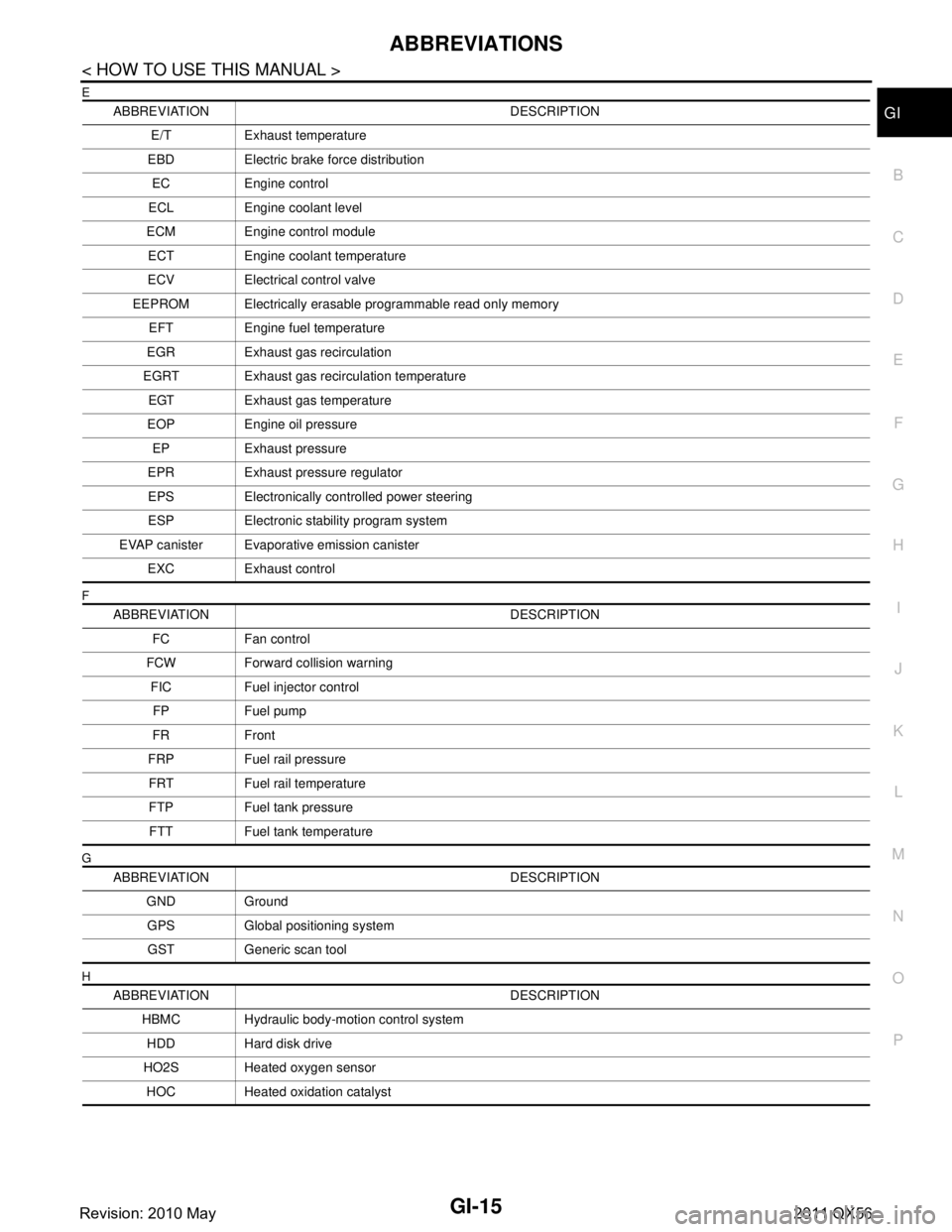
E
F
G
H
ABBREVIATION DESCRIPTION E/T Exhaust temperature
EBD Electric brake force distribution EC Engine control
ECL Engine coolant level
ECM Engine control module ECT Engine coolant temperature
ECV Electrical control valve
EEPROM Electrically erasable programmable read only memory EFT Engine fuel temperature
EGR Exhaust gas recirculation
EGRT Exhaust gas recirculation temperature EGT Exhaust gas temperature
EOP Engine oil pressure EP Exhaust pressure
EPR Exhaust pressure regulator EPS Electronically controlled power steering
ESP Electronic stability program system
EVAP canister Evaporative emission canister EXC Exhaust control
ABBREVIATION DESCRIPTION FC Fan control
FCW Forward collision warning FIC Fuel injector controlFP Fuel pump
FR Front
FRP Fuel rail pressure FRT Fuel rail temperature
FTP Fuel tank pressure FTT Fuel tank temperature
ABBREVIATION DESCRIPTION GND GroundGPS Global positioning systemGST Generic scan tool
ABBREVIATION DESCRIPTION HBMC Hydraulic body-motion control systemHDD Hard disk drive
HO2S Heated oxygen sensor HOC Heated oxidation catalyst
Revision: 2010 May2011 QX56
Page 2992 of 5598
GI-28
< PRECAUTION >
PRECAUTIONS
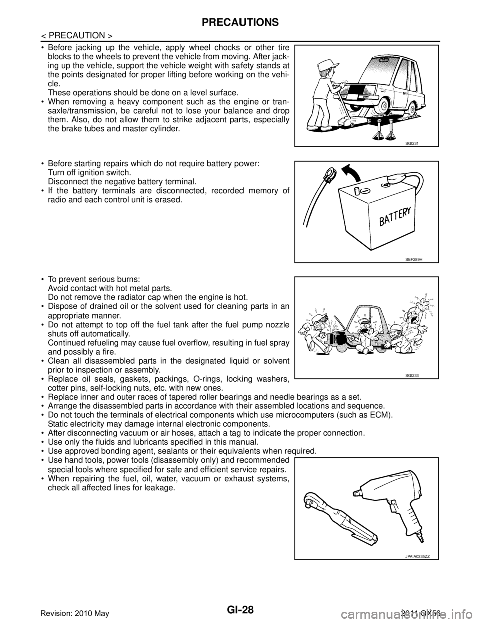
Before jacking up the vehicle, apply wheel chocks or other tireblocks to the wheels to prevent t he vehicle from moving. After jack-
ing up the vehicle, support the vehicle weight with safety stands at
the points designated for proper lifting before working on the vehi-
cle.
These operations should be done on a level surface.
When removing a heavy component such as the engine or tran- saxle/transmission, be careful not to lose your balance and drop
them. Also, do not allow them to strike adjacent parts, especially
the brake tubes and master cylinder.
Before starting repairs which do not require battery power: Turn off ignition switch.
Disconnect the negative battery terminal.
If the battery terminals are disconnected, recorded memory of
radio and each control unit is erased.
To prevent serious burns: Avoid contact with hot metal parts.
Do not remove the radiator cap when the engine is hot.
Dispose of drained oil or the solvent used for cleaning parts in an appropriate manner.
Do not attempt to top off the fuel tank after the fuel pump nozzle
shuts off automatically.
Continued refueling may cause fuel overflow, resulting in fuel spray
and possibly a fire.
Clean all disassembled parts in the designated liquid or solvent prior to inspection or assembly.
Replace oil seals, gaskets, packings, O-rings, locking washers,
cotter pins, self-locking nuts, etc. with new ones.
Replace inner and outer races of tapered roller bearings and needle bearings as a set.
Arrange the disassembled parts in accordance with their assembled locations and sequence.
Do not touch the terminals of electrical com ponents which use microcomputers (such as ECM).
Static electricity may damage internal electronic components.
After disconnecting vacuum or air hoses, atta ch a tag to indicate the proper connection.
Use only the fluids and lubricants specified in this manual.
Use approved bonding agent, sealants or their equivalents when required.
Use hand tools, power tools (disassembly only) and recommended special tools where specified for safe and efficient service repairs.
When repairing the fuel, oil, water, vacuum or exhaust systems, check all affected lines for leakage.
SGI231
SEF289H
SGI233
JPAIA0335ZZ
Revision: 2010 May2011 QX56