Page 2611 of 5598
FUEL INJECTOR AND FUEL TUBEEM-49
< REMOVAL AND INSTALLATION >
C
DE
F
G H
I
J
K L
M A
EM
NP
O
Removal and InstallationINFOID:0000000006289557
REMOVAL
WARNING:
Be sure to read
EM-4, "
Precaution for Handling High Pressure Fuel System" when working on the
high pressure fuel system.
Put a “CAUTION: FLAMMABLE” sign in the workshop.
Be sure to work in a well ventila ted area and furnish workshop with a CO
2 fire extinguisher.
Never smoke while servicing fuel system. Keep op en flames and sparks away from the work area.
To avoid the danger of being scalded, never drain engine coolant when engine is hot.
1. Release fuel pressure. Refer to EC-153, "
Work Procedure".
2. Remove intake manifold. Refer to EM-30, "
Removal and Installation".
3. Remove fuel feed tube (pump side) and fuel feed tube (bank side). CAUTION:
Never reuse fuel feed tube.
4. Remove fuel rail (bank 1) and fuel rail (bank 2).
5. Disconnect harness connector from fuel injectors.
6. Remove fuel injector from cylinder head as per the following: CAUTION:
Be careful with remaining fuel th at may go out from fuel tube.
Be careful not to damage in jector nozzles during removal.
Never bump or drop fuel injector.
Never disassemble fuel injector.
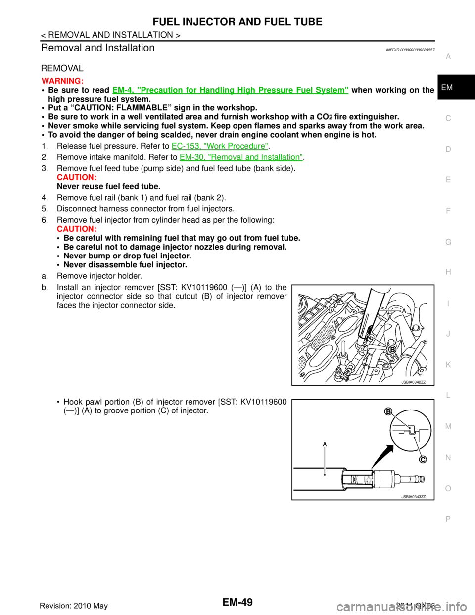
a. Remove injector holder.
b. Install an injector remover [SST: KV10119600 (—)] (A) to the injector connector side so that cutout (B) of injector remover
faces the injector connector side.
Hook pawl portion (B) of injector remover [SST: KV10119600(—)] (A) to groove portion (C) of injector.
JSBIA0342ZZ
JSBIA0343ZZ
Revision: 2010 May2011 QX56
Page 2612 of 5598
EM-50
< REMOVAL AND INSTALLATION >
FUEL INJECTOR AND FUEL TUBE
c. Press down body portion (A) of injector remover [SST:KV10119600 (—)] until it contacts cylinder head.
d. Tighten injector remover [SST: KV10119600 (—)] clockwise and remove injector from cylinder head.
e. Cut Teflon seal (1) while pinching it. Be careful not to damage injector.
f. Remove insulator from mounting ho le of fuel injector of cylinder
head.
INSTALLATION
1. Install seal ring to fuel injector as per the following: CAUTION:
Handle seal ring with bare hands. Never wear gloves.
Never apply engine oil to seal ring.
Never clean seal ring with solvent.
JPBIA3747ZZ
JPBIA3748ZZ
JSBIA0346ZZ
Revision: 2010 May2011 QX56
Page 2613 of 5598
![INFINITI QX56 2011 Factory Service Manual
FUEL INJECTOR AND FUEL TUBEEM-51
< REMOVAL AND INSTALLATION >
C
DE
F
G H
I
J
K L
M A
EM
NP
O
a. Install an injector seal drift set [SST: KV101197S0 (—)] (A) to
fuel injector (1).
b. Set seal ring INFINITI QX56 2011 Factory Service Manual
FUEL INJECTOR AND FUEL TUBEEM-51
< REMOVAL AND INSTALLATION >
C
DE
F
G H
I
J
K L
M A
EM
NP
O
a. Install an injector seal drift set [SST: KV101197S0 (—)] (A) to
fuel injector (1).
b. Set seal ring](/manual-img/42/57033/w960_57033-2612.png)
FUEL INJECTOR AND FUEL TUBEEM-51
< REMOVAL AND INSTALLATION >
C
DE
F
G H
I
J
K L
M A
EM
NP
O
a. Install an injector seal drift set [SST: KV101197S0 (—)] (A) to
fuel injector (1).
b. Set seal ring (1) to injector seal drift set [SST: KV101197S0 (—)]
(A).
c. Straightly insert seal ring (1), which is set in step 2, to fuel injec- tor as shown in the figure and install.
CAUTION:
Be careful that seal ring do es not exceed the groove portion
of fuel injector.
d. Insert injector seal drift set [SST: KV101197S0 (—)] (A) to injec- tor and rotate clockwise and counterclockwise by 90 ° while
pressing seal ring to fit it.
NOTE:
Compress seal ring, because this operation is for rectifying
stretch of seal ring caused by installation and for preventing
sticking when inserting injector into cylinder head.
2. Install O-ring and backup ring to fuel injector. When handing new O-ring and backup ring, paying attention to the following caution items:
CAUTION:
Handle O-ring with bare hands. Never wear gloves.
Lubricate O-ring with new engine oil.
Never clean O-ring with solvent.
Check that O-ring and its mating pa rt are free of foreign material.
When installing O-ring, be careful not to scratch it with tool or fingernails. Also be careful not to
twist or stretch O-ring. If O-ring was stretched wh ile it was being attached, never insert it quickly
into fuel tube.
Insert new O-ring straight into fu el rail. Never decenter or twist it.
JSBIA0347ZZ
JSBIA0348ZZ
JSBIA0350ZZ
JSBIA0351ZZ
Revision: 2010 May2011 QX56
Page 2614 of 5598
EM-52
< REMOVAL AND INSTALLATION >
FUEL INJECTOR AND FUEL TUBE
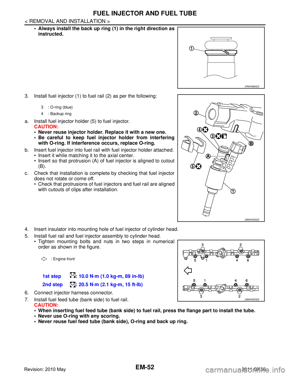
Always install the back up ring (1) in the right direction as
instructed.
3. Install fuel injector (1) to fuel rail (2) as per the following:
a. Install fuel injector holder (5) to fuel injector. CAUTION:
Never reuse injector holder. Replace it with a new one.
Be careful to keep fuel inject or holder from interfering
with O-ring. If interfer ence occurs, replace O-ring.
b. Insert fuel injector into fuel rail with fuel injector holder attached. Insert it while matching it to the axial center.
Insert so that protrusion (A) of fuel injector is aligned to cutout
(B).
c. Check that installation is complete by checking that fuel injector does not rotate or come off.
Check that protrusions of fuel in jectors and fuel rail are aligned
with cutouts of clips after installation.
4. Insert insulator into mounting hole of fuel injector of cylinder head.
5. Install fuel rail and fuel injector assembly to cylinder head. Tighten mounting bolts and nuts in two steps in numericalorder as shown in the figure.
6. Connect injector harness connector.
7. Install fuel feed tube (bank side) to fuel rail. CAUTION:
When inserting fuel feed tube (b ank side) to fuel rail, press the flange part to install the tube.
Never use O-ring with any scoring.
Never reuse fuel feed tube (ban k side), O-ring and back up ring.
JPBIA3864ZZ
3 : O-ring (blue)
4: Backup ring
JSBIA0352ZZ
: Engine front
1st step : 10.0 N·m (1.0 kg-m, 89 in-lb)
2nd step : 20.5 N·m (2.1 kg-m, 15 ft-lb)
JSBIA0353ZZ
Revision: 2010 May2011 QX56
Page 2615 of 5598
FUEL INJECTOR AND FUEL TUBEEM-53
< REMOVAL AND INSTALLATION >
C
DE
F
G H
I
J
K L
M A
EM
NP
O
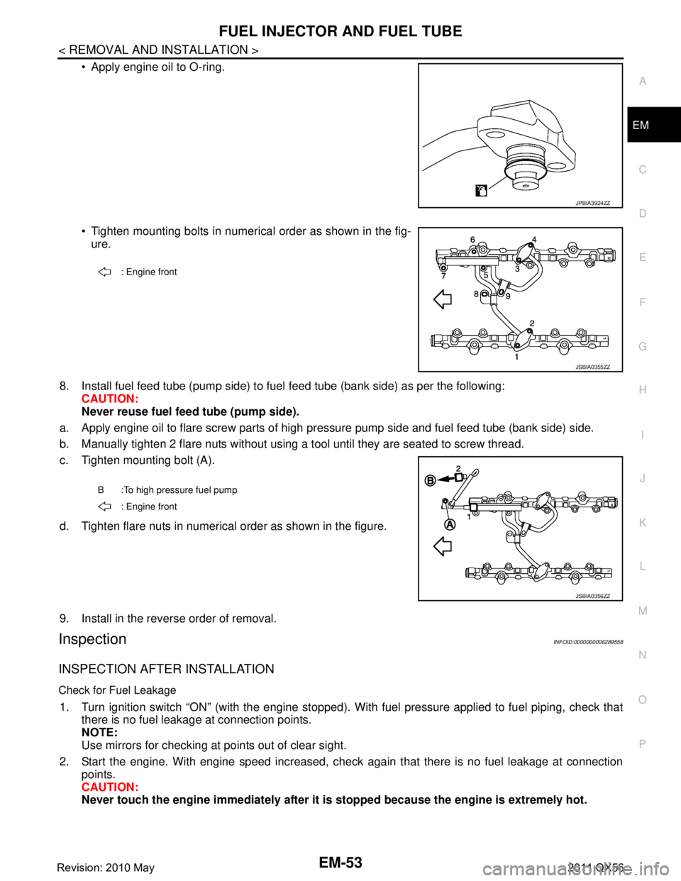
Apply engine oil to O-ring.
Tighten mounting bolts in numerical order as shown in the fig-
ure.
8. Install fuel feed tube (pump side) to fuel feed tube (bank side) as per the following:
CAUTION:
Never reuse fuel feed tube (pump side).
a. Apply engine oil to flare screw parts of high pr essure pump side and fuel feed tube (bank side) side.
b. Manually tighten 2 flare nuts without using a t ool until they are seated to screw thread.
c. Tighten mounting bolt (A).
d. Tighten flare nuts in numerical order as shown in the figure.
9. Install in the reverse order of removal.
InspectionINFOID:0000000006289558
INSPECTION AFTER INSTALLATION
Check for Fuel Leakage
1. Turn ignition switch “ON” (with the engine stopped). With fuel pressure applied to fuel piping, check that
there is no fuel leakage at connection points.
NOTE:
Use mirrors for checking at points out of clear sight.
2. Start the engine. With engine speed increased, check again that there is no fuel leakage at connection
points.
CAUTION:
Never touch the engine immediately after it is stopped because the engine is extremely hot.
JPBIA3924ZZ
: Engine front
JSBIA0355ZZ
B :To high pressure fuel pump
: Engine front
JSBIA0356ZZ
Revision: 2010 May2011 QX56
Page 2623 of 5598
TIMING CHAINEM-61
< REMOVAL AND INSTALLATION >
C
DE
F
G H
I
J
K L
M A
EM
NP
O
TIMING CHAIN
Exploded ViewINFOID:0000000006289565
1. O-ring 2. O-ring 3. O-ring
4. Tension guide (bank 2) 5. High pressure fuel pump camshaft 6. Timing chain (bank 2)
7. Lifter 8. Intake camshaft sprocket (bank 2) 9. Exhaust camshaft sprocket (bank 2)
JPBIA4597GB
Revision: 2010 May2011 QX56
Page 2624 of 5598
EM-62
< REMOVAL AND INSTALLATION >
TIMING CHAIN
Removal and Installation
INFOID:0000000006289566
REMOVAL
1. Release fuel pressure. Refer to EC-153, "Work Procedure".
2. Drain engine coolant from radiator. Refer to CO-8, "
Draining".
3. Remove fan shroud (lower). Refer to CO-13, "
Exploded View".
4. Remove fan bracket. Refer to CO-16, "
Exploded View".
5. Remove drive belt auto-tensioner. Refer to EM-26, "
Exploded View".
6. Remove oil level gauge and oil level gauge guide. Refer to EM-57, "
Exploded View".
7. Move power steering oil pump to the posit ion without the hindrance for work. Refer to ST-48, "
Exploded
View".
8. Remove alternator, alternator bracket and alternator stay. Refer to CHG-25, "
Exploded View".
9. Move power steering reservoir tank to the position without the hindrance for work, and then remove Res- ervoir tank bracket. Refer to ST-54, "
Exploded View".
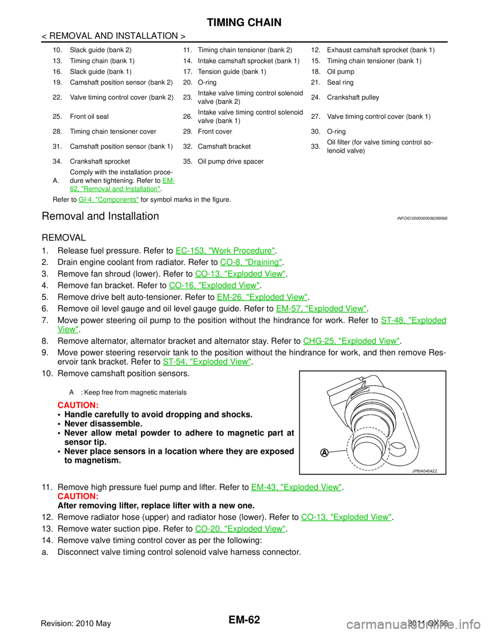
10. Remove camshaft position sensors.
CAUTION:
Handle carefully to avoid dropping and shocks.
Never disassemble.
Never allow metal powder to adhere to magnetic part atsensor tip.
Never place sensors in a lo cation where they are exposed
to magnetism.
11. Remove high pressure fuel pump and lifter. Refer to EM-43, "
Exploded View".
CAUTION:
After removing lifter, replace lifter with a new one.
12. Remove radiator hose (upper) and radiator hose (lower). Refer to CO-13, "
Exploded View".
13. Remove water suction pipe. Refer to CO-20, "
Exploded View".
14. Remove valve timing control cover as per the following:
a. Disconnect valve timing control solenoid valve harness connector.
10. Slack guide (bank 2) 11. Timing chain tensioner (bank 2) 12. Exhaust camshaft sprocket (bank 1)
13. Timing chain (bank 1) 14. Intake camshaft sprocket (bank 1) 15. Timing chain tensioner (bank 1)
16. Slack guide (bank 1) 17. Tension guide (bank 1) 18. Oil pump
19. Camshaft position sensor (bank 2) 20. O-ring 21. Seal ring
22. Valve timing control cover (bank 2) 23. Intake valve timing control solenoid
valve (bank 2)24. Crankshaft pulley
25. Front oil seal 26. Intake valve timing control solenoid
valve (bank 1)27. Valve timing control cover (bank 1)
28. Timing chain tensioner cover 29. Front cover 30. O-ring
31. Camshaft position sensor (bank 1) 32. Camshaft bracket 33. Oil filter (for valve timing control so-
lenoid valve)
34. Crankshaft sprocket 35. Oil pump drive spacer
A. Comply with the installation proce-
dure when tightening. Refer to
EM-
62, "Removal and Installation".
Refer to GI-4, "
Components" for symbol marks in the figure.
A : Keep free from magnetic materials
JPBIA0454ZZ
Revision: 2010 May2011 QX56
Page 2626 of 5598
EM-64
< REMOVAL AND INSTALLATION >
TIMING CHAIN
24. Remove oil pump and oil pump drive spacer.
25. Remove front oil seal from front cover using suitable tool. Use screwdriver for removal.
CAUTION:
Be careful not to damage front cover.
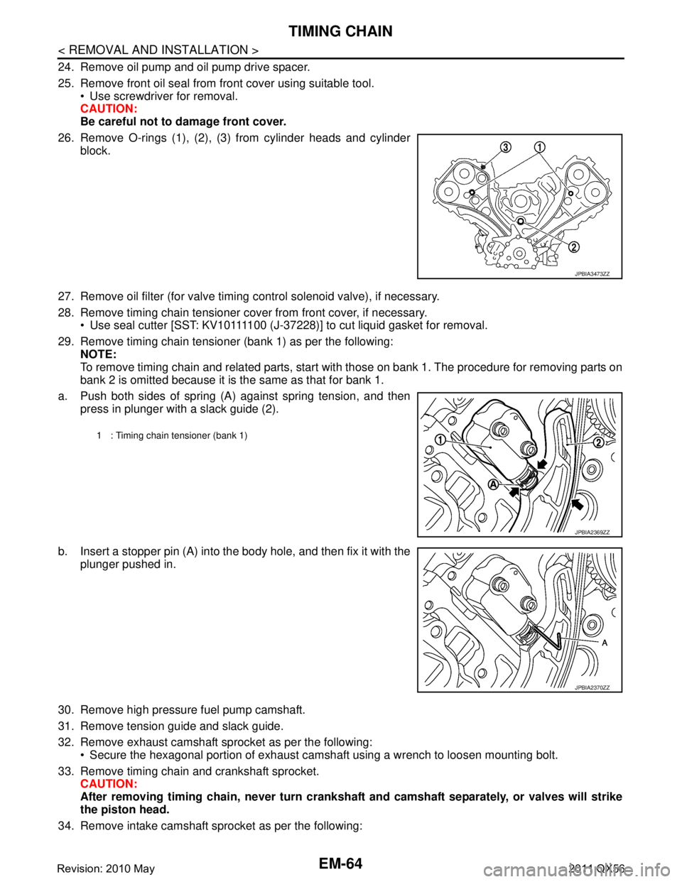
26. Remove O-rings (1), (2), (3) from cylinder heads and cylinder block.
27. Remove oil filter (for valve timing control solenoid valve), if necessary.
28. Remove timing chain tensioner cover from front cover, if necessary. Use seal cutter [SST: KV10111100 (J-37228)] to cut liquid gasket for removal.
29. Remove timing chain tensioner (bank 1) as per the following: NOTE:
To remove timing chain and related parts, start with those on bank 1. The procedure for removing parts on
bank 2 is omitted because it is the same as that for bank 1.
a. Push both sides of spring (A) against spring tension, and then press in plunger with a slack guide (2).
b. Insert a stopper pin (A) into the body hole, and then fix it with the
plunger pushed in.
30. Remove high pressure fuel pump camshaft.
31. Remove tension guide and slack guide.
32. Remove exhaust camshaft sprocket as per the following: Secure the hexagonal portion of exhaust camshaf t using a wrench to loosen mounting bolt.
33. Remove timing chain and crankshaft sprocket. CAUTION:
After removing timing chain, never turn cranksh aft and camshaft separately, or valves will strike
the piston head.
34. Remove intake camshaft sprocket as per the following:
JPBIA3473ZZ
1 : Timing chain tensioner (bank 1)
JPBIA2369ZZ
JPBIA2370ZZ
Revision: 2010 May2011 QX56