2011 INFINITI QX56 width
[x] Cancel search: widthPage 2185 of 5598
![INFINITI QX56 2011 Factory Service Manual
TROUBLE DIAGNOSIS - SPECIFICATION VALUEEC-161
< DTC/CIRCUIT DIAGNOSIS > [VK56VD]
C
D
E
F
G H
I
J
K L
M A
EC
NP
O
DTC/CIRCUIT DIAGNOSIS
TROUBLE DIAGNOSIS - SPECIFICATION VALUE
DescriptionINFOID:000000 INFINITI QX56 2011 Factory Service Manual
TROUBLE DIAGNOSIS - SPECIFICATION VALUEEC-161
< DTC/CIRCUIT DIAGNOSIS > [VK56VD]
C
D
E
F
G H
I
J
K L
M A
EC
NP
O
DTC/CIRCUIT DIAGNOSIS
TROUBLE DIAGNOSIS - SPECIFICATION VALUE
DescriptionINFOID:000000](/manual-img/42/57033/w960_57033-2184.png)
TROUBLE DIAGNOSIS - SPECIFICATION VALUEEC-161
< DTC/CIRCUIT DIAGNOSIS > [VK56VD]
C
D
E
F
G H
I
J
K L
M A
EC
NP
O
DTC/CIRCUIT DIAGNOSIS
TROUBLE DIAGNOSIS - SPECIFICATION VALUE
DescriptionINFOID:0000000006217760
The specification (SP) value indicates the tolerance of
the value that is displayed in “SPEC” in “DATA MONI-
TOR” mode of CONSULT-III during normal operation of the Engine Control System. When the value in “SPEC”
in “DATA MONITOR” mode is within the SP value, t he Engine Control System is confirmed OK. When the
value in “SPEC” in “DATA MONITOR” mode is NOT wit hin the SP value, the Engine Control System may have
one or more malfunctions.
The SP value is used to detect malfunctions that may affect the Engine Control System, but will not illuminate
the MIL.
The SP value will be displayed for the following items:
B/FUEL SCHDL (The fuel injection pulse width programmed into ECM prior to any learned on board correc- tion)
A/F ALPHA-B1/B2 (The mean value of air-fuel ratio feedback correction factor per cycle)
MAS A/F SE-B1/B2 (The signal voltage of the mass air flow sensor)
IDLE FUEL PRES MAX/MIN (the signal voltage of the fuel rail pressure sensor)
Component Function CheckINFOID:0000000006217761
1.PRECONDITIONING
Check that all of the following conditions are satisfied.
TESTING CONDITION
Vehicle driven distance: More than 5,000 km (3,107 miles)
Barometric pressure: 98.3 - 104.3 kPa (0.983 - 1.043 bar, 1.003 - 1.064 kg/cm
2, 14.25 - 15.12 psi)
Atmospheric temperature: 20 - 30 °C (68 - 86 °F)
Engine coolant temperature: 75 - 95 °C (167 - 203 °F)
Transmission: Warmed-up
- After the engine is warmed up to normal operating temperat ure, drive vehicle until “ATF TEMP 2” (A/T fluid
temperature sensor signal) indicates more than 60 °C (140 °F).
Electrical load: Not applied
- Rear window defogger switch, air conditioner switch and li ghting switch are OFF. Steering wheel is straight
ahead.
Engine speed: Idle
Gear position: Neutral ( or parking)
>> GO TO 2.
2.PERFORM SPEC IN DATA MONITOR MODE
WITH CONSULT-III
NOTE:
Perform “SPEC” in “DATA MONITOR” mode in maximum scale display.
1. Perform EC-139, "
Work Procedure".
2. Select “B/FUEL SCHDL”, “A/F ALPHA-B1”, “A/F ALPHA-B2”, “MAS A/F SE-B1” in “SPEC” of “DATA
MONITOR” mode with CONSULT-III.
3. Check that monitor items are within the SP value.
Is the measurement value within the SP value?
YES >> INSPECTION END
NO >> Proceed to EC-162, "
Diagnosis Procedure".
Revision: 2010 May2011 QX56
Page 2684 of 5598
EM-122
< UNIT DISASSEMBLY AND ASSEMBLY >
CYLINDER BLOCK
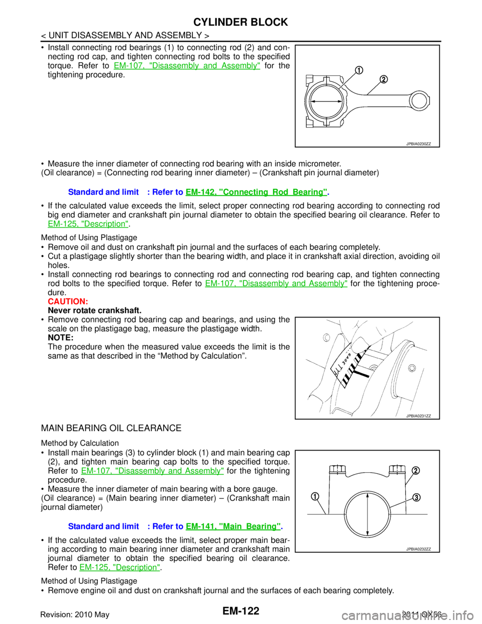
Install connecting rod bearings (1) to connecting rod (2) and con-necting rod cap, and tighten connecting rod bolts to the specified
torque. Refer to EM-107, "
Disassembly and Assembly" for the
tightening procedure.
Measure the inner diameter of connecting rod bearing with an inside micrometer.
(Oil clearance) = (Connecting rod bearing inner di ameter) – (Crankshaft pin journal diameter)
If the calculated value exceeds the limit, select proper connecting rod bearing according to connecting rod
big end diameter and crankshaft pin journal diameter to obtain the specified bearing oil clearance. Refer to
EM-125, "
Description".
Method of Using Plastigage
Remove oil and dust on crankshaft pin journal and the surfaces of each bearing completely.
Cut a plastigage slightly shorter than the bearing width, and place it in crankshaft axial direction, avoiding oil
holes.
Install connecting rod bearings to connecting rod and connecting rod bearing cap, and tighten connecting
rod bolts to the specified torque. Refer to EM-107, "
Disassembly and Assembly" for the tightening proce-
dure.
CAUTION:
Never rotate crankshaft.
Remove connecting rod bearing cap and bearings, and using the
scale on the plastigage bag, measure the plastigage width.
NOTE:
The procedure when the measured va lue exceeds the limit is the
same as that described in the “Method by Calculation”.
MAIN BEARING OIL CLEARANCE
Method by Calculation
Install main bearings (3) to cylinder block (1) and main bearing cap (2), and tighten main bearing cap bolts to the specified torque.
Refer to EM-107, "
Disassembly and Assembly" for the tightening
procedure.
Measure the inner diameter of main bearing with a bore gauge.
(Oil clearance) = (Main bearing inner diameter) – (Crankshaft main
journal diameter)
If the calculated value exceeds t he limit, select proper main bear-
ing according to main bearing inner diameter and crankshaft main
journal diameter to obtain the specified bearing oil clearance.
Refer to EM-125, "
Description".
Method of Using Plastigage
Remove engine oil and dust on crankshaft journal and the surfaces of each bearing completely.
JPBIA0230ZZ
Standard and limit : Refer to EM-142, "ConnectingRodBearing".
JPBIA0231ZZ
Standard and limit : Refer to EM-141, "MainBearing".
JPBIA0232ZZ
Revision: 2010 May2011 QX56
Page 2685 of 5598
CYLINDER BLOCKEM-123
< UNIT DISASSEMBLY AND ASSEMBLY >
C
DE
F
G H
I
J
K L
M A
EM
NP
O
Cut a plastigage slightly shorter than the bearing width,
and place it in crankshaft axial direction, avoiding oil
holes.
Install main bearing to cylinder block and main bearing cap, and tighten main bearing cap bolts with main
bearing cap to the specified torque. Refer to EM-107, "
Disassembly and Assembly" for the tightening proce-
dure.
CAUTION:
Never rotate crankshaft.
Remove main bearing cap and bearings, and using the scale on the plastigage bag, measure the plastigage width.
NOTE:
The procedure when the measured value exceeds the limit is the
same as that described in the “Method by Calculation”.
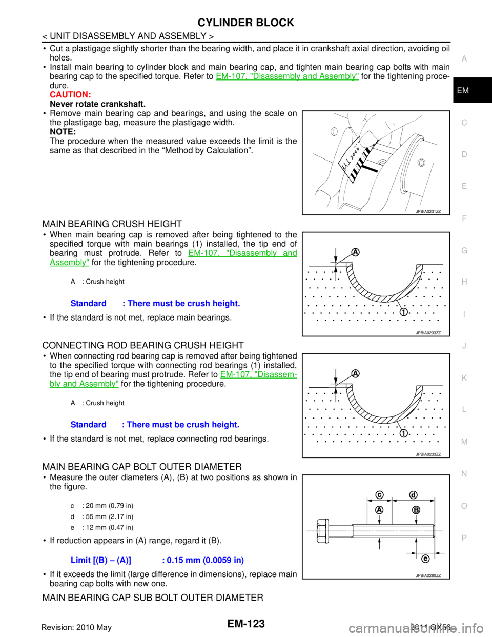
MAIN BEARING CRUSH HEIGHT
When main bearing cap is removed after being tightened to thespecified torque with main bearings (1) installed, the tip end of
bearing must protrude. Refer to EM-107, "
Disassembly and
Assembly" for the tightening procedure.
If the standard is not met, replace main bearings.
CONNECTING ROD BEARING CRUSH HEIGHT
When connecting rod bearing cap is removed after being tightened to the specified torque with connecting rod bearings (1) installed,
the tip end of bearing must protrude. Refer to EM-107, "
Disassem-
bly and Assembly" for the tightening procedure.
If the standard is not met, replace connecting rod bearings.
MAIN BEARING CAP BOLT OUTER DIAMETER
Measure the outer diameters (A), (B) at two positions as shown in
the figure.
If reduction appears in (A) range, regard it (B).
If it exceeds the limit (large difference in dimensions), replace main bearing cap bolts with new one.
MAIN BEARING CAP SUB BOLT OUTER DIAMETER
JPBIA0231ZZ
A : Crush height
Standard : There must be crush height.
JPBIA0233ZZ
A : Crush height
Standard : There must be crush height.
JPBIA0233ZZ
c : 20 mm (0.79 in)
d : 55 mm (2.17 in)
e : 12 mm (0.47 in)
Limit [(B) – (A)] : 0.15 mm (0.0059 in)
JPBIA2280ZZ
Revision: 2010 May2011 QX56
Page 2699 of 5598
SERVICE DATA AND SPECIFICATIONS (SDS)
EM-137
< SERVICE DATA AND SPECIFICATIONS (SDS)
C
D E
F
G H
I
J
K L
M A
EM
NP
O
*1: Diameter made by intersection point of conic angles “
α1” and “ α2”
*
2: Diameter made by intersection point of conic angles “ α2” and “ α3”
*
3: Machining data
*
4: Parts settings are for exhaust side only
VALVE SPRING
Cylinder BlockINFOID:0000000006289595
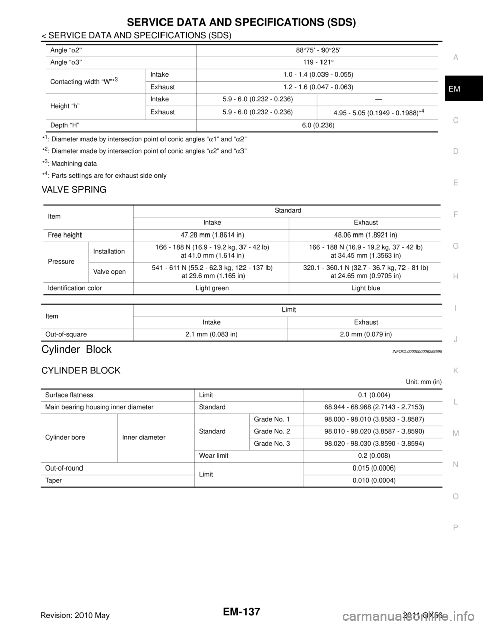
CYLINDER BLOCK
Unit: mm (in)
Angle “ α2” 88°75 ′ - 90 °25 ′
Angle “ α3” 11 9 - 1 2 1°
Contacting width “W”*
3Intake 1.0 - 1.4 (0.039 - 0.055)
Exhaust 1.2 - 1.6 (0.047 - 0.063)
Height “h” Intake 5.9 - 6.0 (0.232 - 0.236) —
Exhaust 5.9 - 6.0 (0.232 - 0.236)
4.95 - 5.05 (0.1949 - 0.1988)*
4
Depth “H” 6.0 (0.236)
ItemStandard
Intake Exhaust
Free height 47.28 mm (1.8614 in) 48.06 mm (1.8921 in)
Pressure Installation
166 - 188 N (16.9 - 19.2 kg, 37 - 42 lb)
at 41.0 mm (1.614 in) 166 - 188 N (16.9 - 19.2 kg, 37 - 42 lb)
at 34.45 mm (1.3563 in)
Valve open 541 - 611 N (55.2 - 62.3 kg, 122 - 137 lb)
at 29.6 mm (1.165 in) 320.1 - 360.1 N (32.7 - 36.7 kg, 72 - 81 lb)
at 24.65 mm (0.9705 in)
Identification color Light green Light blue
Item Limit
Intake Exhaust
Out-of-square 2.1 mm (0.083 in) 2.0 mm (0.079 in)
Surface flatness Limit 0.1 (0.004)
Main bearing housing inner diameter Standard 68.944 - 68.968 (2.7143 - 2.7153)
Cylinder bore Inner diameter StandardGrade No. 1 98.000 - 98.010 (3.8583 - 3.8587)
Grade No. 2 98.010 - 98.020 (3.8587 - 3.8590)
Grade No. 3 98.020 - 98.030 (3.8590 - 3.8594)
Wear limit 0.2 (0.008)
Out-of-round Limit0.015 (0.0006)
Ta p e r 0.010 (0.0004)
Revision: 2010 May2011 QX56
Page 2703 of 5598
SERVICE DATA AND SPECIFICATIONS (SDS)
EM-141
< SERVICE DATA AND SPECIFICATIONS (SDS)
C
D E
F
G H
I
J
K L
M A
EM
NP
O
*: Total indicator reading
Main BearingINFOID:0000000006289596
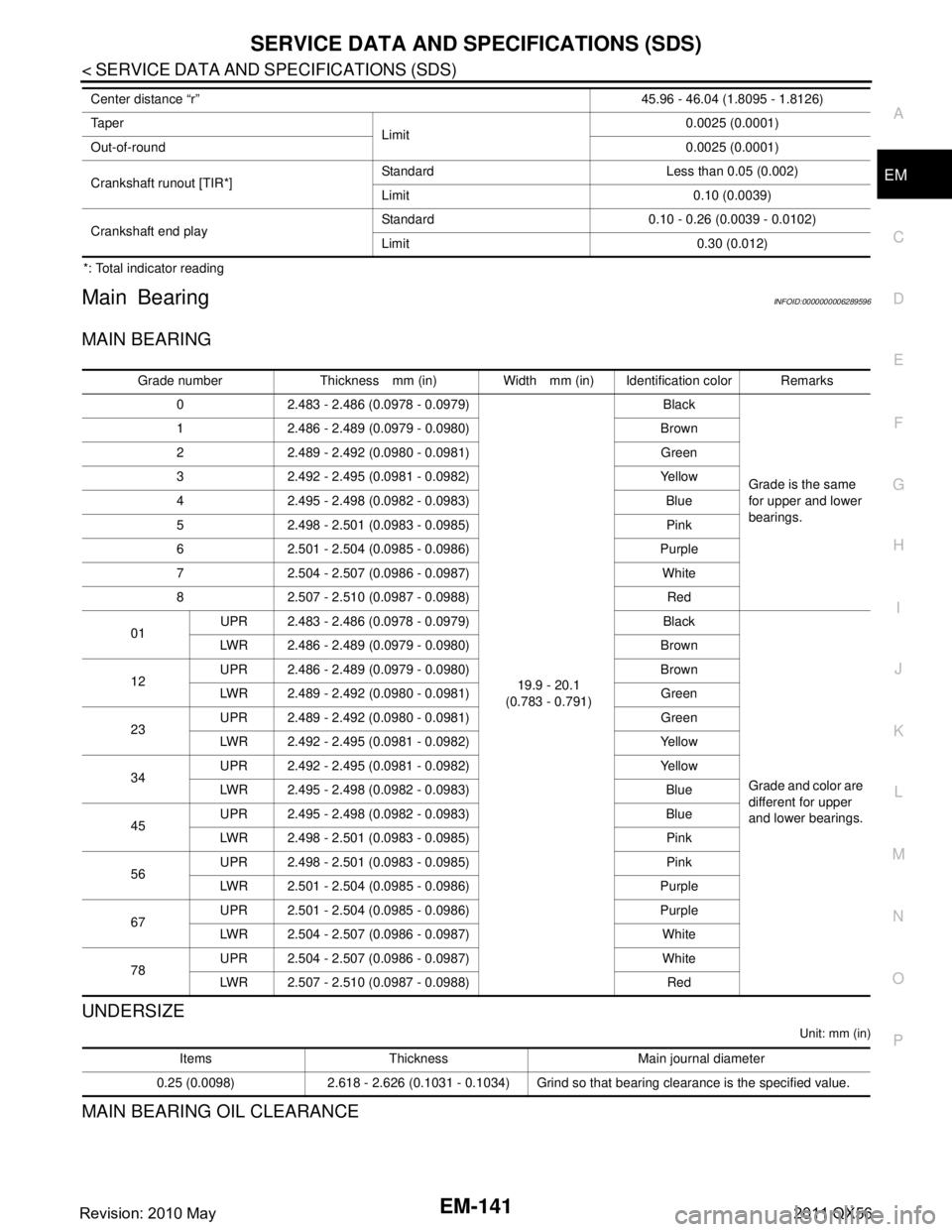
MAIN BEARING
UNDERSIZE
Unit: mm (in)
MAIN BEARING OIL CLEARANCE
Center distance “r”
45.96 - 46.04 (1.8095 - 1.8126)
Ta p e r Limit 0.0025 (0.0001)
Out-of-round 0.0025 (0.0001)
Crankshaft runout [TIR*] Standard Less than 0.05 (0.002)
Limit 0.10 (0.0039)
Crankshaft end play Standard 0.10 - 0.26 (0.0039 - 0.0102)
Limit 0.30 (0.012)
Grade number Thickness mm (in) Width mm (in) Identification color Remarks
0 2.483 - 2.486 (0.0978 - 0.0979)
19.9 - 20.1
(0.783 - 0.791) Black
Grade is the same
for upper and lower
bearings.
1 2.486 - 2.489 (0.0979 - 0.0980) Brown
2 2.489 - 2.492 (0.0980 - 0.0981) Green
3 2.492 - 2.495 (0.0981 - 0.0982) Yellow
4 2.495 - 2.498 (0.0982 - 0.0983) Blue
5 2.498 - 2.501 (0.0983 - 0.0985) Pink
6 2.501 - 2.504 (0.0985 - 0.0986) Purple
7 2.504 - 2.507 (0.0986 - 0.0987) White
8 2.507 - 2.510 (0.0987 - 0.0988) Red
01 UPR 2.483 - 2.486 (0.0978 - 0.0979) Black
Grade and color are
different for upper
and lower bearings.
LWR 2.486 - 2.489 (0.0979 - 0.0980) Brown
12 UPR 2.486 - 2.489 (0.0979 - 0.0980) Brown
LWR 2.489 - 2.492 (0.0980 - 0.0981) Green
23 UPR 2.489 - 2.492 (0.0980 - 0.0981) Green
LWR 2.492 - 2.495 (0.0981 - 0.0982) Yellow
34 UPR 2.492 - 2.495 (0.0981 - 0.0982) Yellow
LWR 2.495 - 2.498 (0.0982 - 0.0983) Blue
45 UPR 2.495 - 2.498 (0.0982 - 0.0983) Blue
LWR 2.498 - 2.501 (0.0983 - 0.0985) Pink
56 UPR 2.498 - 2.501 (0.0983 - 0.0985) Pink
LWR 2.501 - 2.504 (0.0985 - 0.0986) Purple
67 UPR 2.501 - 2.504 (0.0985 - 0.0986) Purple
LWR 2.504 - 2.507 (0.0986 - 0.0987) White
78 UPR 2.504 - 2.507 (0.0986 - 0.0987) White
LWR 2.507 - 2.510 (0.0987 - 0.0988) Red
Items Thickness Main journal diameter
0.25 (0.0098) 2.618 - 2.626 (0.1031 - 0.1034) Grind so that bearing clearance is the specified value.
Revision: 2010 May2011 QX56
Page 2704 of 5598

EM-142
< SERVICE DATA AND SPECIFICATIONS (SDS)
SERVICE DATA AND SPECIFICATIONS (SDS)
Unit: mm (in)
*: Actual clearance
Connecting Rod BearingINFOID:0000000006289597
CONNECTING ROD BEARING
UNDERSIZE
Unit: mm (in)
CONNECTING ROD BEARING OIL CLEARANCE
Unit: mm (in)
*: Actual clearanceItems Standard Limit
Main bearing oil clearance No.1 and 5 0.001 - 0.011 (0.00004 - 0.00043)*
0.065 (0.0026)
No.2, 3 and 4 0.007 - 0.017 (0.0003 - 0.0007)*
Grade number Thickness mm (in) Width mm (in) Identification color (mark)
1 1.500 - 1.503 (0.0591 - 0.0592)
18.1 - 18.3
(0.713 - 0.720) Black
2 1.503 - 1.506 (0.0592 - 0.0593) Brown
3 1.506 - 1.509 (0.0593 - 0.0594) Green
4 1.509 - 1.512 (0.0594 - 0.0595) Yellow
Items Thickness Pin journal diameter
0.25 (0.0098) 1.627 - 1.635 (0.0641 - 0.0644) Grind so that bearing clearance is the specified value.
Items Standard Limit
Connecting rod bearing oil clearance 0.020 - 0.039 (0.0008 - 0.0015)* 0.070 (0.0028)
Revision: 2010 May2011 QX56
Page 2707 of 5598

PREPARATIONEX-3
< PREPARATION >
C
DE
F
G H
I
J
K L
M A
EX
NP
O
PREPARATION
PREPARATION
Special Service ToolINFOID:0000000006289692
Commercial Service ToolINFOID:0000000006289693
Tool number
(Kent-Moore No.)
Tool name
Description
KV10114400
(J-38365)
Heated oxygen sensor wrench Loosening or tightening heated oxygen sen-
sor 2
For 22 mm (0.87 in) (a) width hexagon nut
S-NT636
Tool name
Description
Power tool Loosening bolts and nuts
PBIC0190E
Revision: 2010 May2011 QX56
Page 2981 of 5598
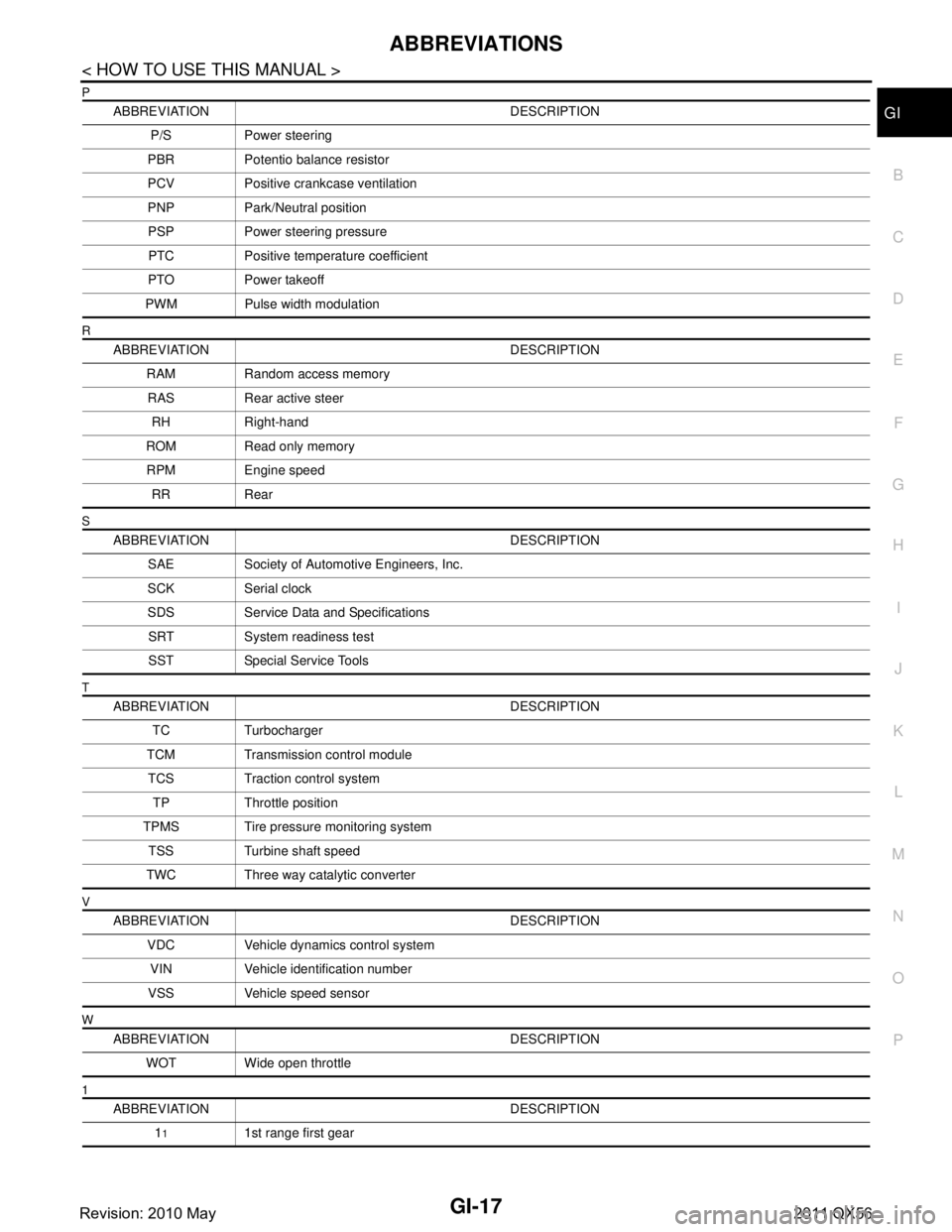
ABBREVIATIONSGI-17
< HOW TO USE THIS MANUAL >
C
DE
F
G H
I
J
K L
M B
GI
N
O P
P
R
S
T
V
W
1
ABBREVIATION DESCRIPTION P/S Power steering
PBR Potentio balance resistor
PCV Positive crankcase ventilation
PNP Park/Neutral position PSP Power steering pressurePTC Positive temperature coefficient
PTO Power takeoff
PWM Pulse width modulation
ABBREVIATION DESCRIPTION RAM Random access memoryRAS Rear active steer RH Right-hand
ROM Read only memory RPM Engine speed RR Rear
ABBREVIATION DESCRIPTION SAE Society of Automoti ve Engineers, Inc.
SCK Serial clock
SDS Service Data and Specifications SRT System readiness testSST Special Service Tools
ABBREVIATION DESCRIPTION TC Turbocharger
TCM Transmission control module TCS Traction control system TP Throttle position
TPMS Tire pressure monitoring system TSS Turbine shaft speed
TWC Three way catalytic converter
ABBREVIATION DESCRIPTION VDC Vehicle dynamics control systemVIN Vehicle identification number
VSS Vehicle speed sensor
ABBREVIATION DESCRIPTION WOT Wide open throttle
ABBREVIATION DESCRIPTION 1
11st range first gear
Revision: 2010 May2011 QX56