2011 INFINITI QX56 wheel alignment
[x] Cancel search: wheel alignmentPage 2963 of 5598
SERVICE DATA AND SPECIFICATIONS (SDS)
FSU-21
< SERVICE DATA AND SPECIFICATIONS (SDS)
C
D F
G H
I
J
K L
M A
B
FSU
N
O P
SERVICE DATA AND SPECIFICATIONS (SDS)
SERVICE DATA AND SPECIFICATIONS (SDS)
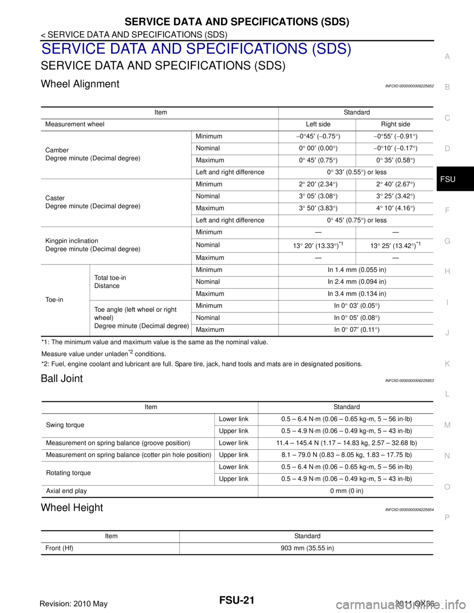
Wheel AlignmentINFOID:0000000006225652
*1: The minimum value and maximum value is the same as the nominal value.
Measure value under unladen
*2 conditions.
*2: Fuel, engine coolant and lubricant are full. Spare tire, jack, hand tools and mats are in designated positions.
Ball JointINFOID:0000000006225653
Wheel HeightINFOID:0000000006225654
Item Standard
Measurement wheel Left side Right side
Camber
Degree minute (Decimal degree) Minimum
−0 °45 ′ ( −0.75 °) −0°55 ′ ( −0.91 °)
Nominal 0 ° 00 ′ (0.00 °) −0°10 ′ ( −0.17 °)
Maximum 0 ° 45 ′ (0.75 °)0 ° 35 ′ (0.58 °)
Left and right difference 0 ° 33 ′ (0.55 °) or less
Caster
Degree minute (Decimal degree) Minimum 2
° 20 ′ (2.34 °)2 ° 40 ′ (2.67 °)
Nominal 3 ° 05 ′ (3.08 °)3 ° 25 ′ (3.42 °)
Maximum 3 ° 50 ′ (3.83 °)4 ° 10 ′ (4.16
° )
Left and right difference 0 ° 45 ′ (0.75 °) or less
Kingpin inclination
Degree minute (Decimal degree) Minimum — —
Nominal
13° 20 ′ (13.33 °)
*113 ° 25 ′ (13.42 °)*1
Maximum — —
To e - i n To t a l t o e - i n
Distance
Minimum In 1.4 mm (0.055 in)
Nominal In 2.4 mm (0.094 in)
Maximum In 3.4 mm (0.134 in)
Toe angle (left wheel or right
wheel)
Degree minute (Decimal degree) Minimum In 0
° 03 ′ (0.05 °)
Nominal In 0 ° 05 ′ (0.08 °)
Maximum In 0 ° 07 ′ (0.11 °)
Item Standard
Swing torque Lower link 0.5 – 6.4 N·m (0.06 – 0.65 kg-m, 5 – 56 in-lb)
Upper link 0.5 – 4.9 N·m (0.06 – 0.49 kg-m, 5 – 43 in-lb)
Measurement on spring balance (groove position) Lower link 11.4 – 145.4 N (1.17 – 14.83 kg, 2.57 – 32.68 lb)
Measurement on spring balance (cotter pin hole position) Upper link 8.1 – 79.0 N (0.83 – 8.05 kg, 1.83 – 17.75 lb)
Rotating torque Lower link 0.5 – 6.4 N·m (0.06 – 0.65 kg-m, 5 – 56 in-lb)
Upper link 0.5 – 4.9 N·m (0.06 – 0.49 kg-m, 5 – 43 in-lb)
Axial end play 0 mm (0 in)
Item Standard
Front (Hf) 903 mm (35.55 in)
Revision: 2010 May2011 QX56
Page 3674 of 5598
MA-4
< PERIODIC MAINTENANCE >
GENERAL MAINTENANCE
PERIODIC MAINTENANCE
GENERAL MAINTENANCE
Explanation of General MaintenanceINFOID:0000000006287728
General maintenance includes those items which shoul d be checked during the normal day-to-day operation
of the vehicle. They are essential if the vehicle is to continue operating properly. The owners can perform
checks and inspections themselves or have their INFINITI dealers do them.
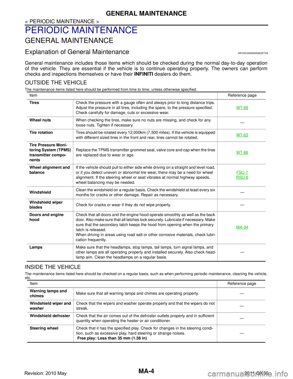
OUTSIDE THE VEHICLE
The maintenance items listed here should be performed fr om time to time, unless otherwise specified.
INSIDE THE VEHICLE
The maintenance items listed here should be checked on a regular basis, such as when performing periodic maintenance, cleaning the vehicle,
etc.
Item Reference page
Tires Check the pressure with a gauge often and always prior to long distance trips.
Adjust the pressure in all tires, including the spare, to the pressure specified.
Check carefully for damage, cuts or excessive wear. WT-69
Wheel nuts
When checking the tires, make sure no nuts are missing, and check for any
loose nuts. Tighten if necessary. —
Tire rotation Tires should be rotated every 12,000km (7,500 miles). If the vehicle is equipped
with different sized tires in the front and rear, tires cannot be rotated. WT-63
Tire Pressure Moni-
toring System (TPMS)
transmitter compo-
nentsReplace the TPMS transmitter grommet seal, valve core and cap when the tires
are replaced due to wear or age.
WT-66
Wheel alignment and
balanceIf the vehicle should pull to either side while driving on a straight and level road,
or if you detect uneven or abnormal tire wear, there may be a need for wheel
alignment. If the steering wheel or seat vibrates at normal highway speeds,
wheel balancing may be needed. FSU-7
RSU-6
Windshield
Clean the windshield on a regular basis. Check the windshield at least every six
months for cracks or other damage. Repair as necessary. —
Windshield wiper
blades Check for cracks or wear if they do not wipe properly. —
Doors and engine
hood Check that all doors and the engine hood operate smoothly as well as the back
door. Also make sure that all latches lock securely. Lubricate if necessary. Make
sure that the secondary latch keeps the hood from opening when the primary
latch is released.
When driving in areas using road salt or other corrosive materials, check lubri-
cation frequently. MA-34
Lamps
Make sure that the headlamps, stop lamps, tail lamps, turn signal lamps, and
other lamps are all operating properly and installed securely. Also check head-
lamp aim. Clean the headlamps on a regular basis. —
Item
Reference page
Warning lamps and
chimes Make sure that all warning lamps and chimes are operating properly. —
Windshield wiper and
washer Check that the wipers and washer operate properly and that the wipers do not
streak.
—
Windshield defroster Check that the air comes out of the defroster outlets properly and in sufficient
quantity when operating the heater or air conditioner. —
Steering wheel Check that it has the specified play. Check for changes in the steering condi-
tion, such as excessive play, hard steering or strange noises.
Free play: Less than 35 mm (1.38 in) —
Revision: 2010 May2011 QX56
Page 4205 of 5598
REAR WHEEL HUB AND HOUSINGRAX-9
< REMOVAL AND INSTALLATION >
CEF
G H
I
J
K L
M A
B
RAX
N
O P
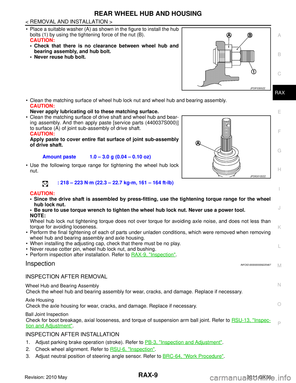
Place a suitable washer (A) as shown in the figure to install the hub bolts (1) by using the tightening force of the nut (B).
CAUTION:
Check that there is no cl earance between wheel hub and
bearing assembly, and hub bolt.
Never reuse hub bolt.
Clean the matching surface of wheel hub lock nut and wheel hub and bearing assembly. CAUTION:
Never apply lubricating oi l to these matching surface.
Clean the matching surface of drive shaft and wheel hub and bear-
ing assembly. And then apply paste [service parts (440037S000)]
to surface (A) of joint sub-assembly of drive shaft.
CAUTION:
Apply paste to cover entire fl at surface of joint sub-assembly
of drive shaft.
Use the following torque range for tightening the wheel hub lock nut.
CAUTION:
Since the drive shaft is assembled by press-fitting , use the tightening torque range for the wheel
hub lock nut.
Be sure to use torque wrench to tighten th e wheel hub lock nut. Never use a power tool.
NOTE:
Wheel hub lock nut tightening torque does not over tor que for avoiding axle noise, and does not less than
torque for avoiding looseness.
Perform the final tightening of each of parts under unladen conditions, which were removed when removing wheel hub and bearing assembly and axle housing.
When installing the adjusting cap, check that there must be no play.
Never reuse cotter pin, wheel hub lock nut, and bushing.
Perform inspection after installation. Refer to RAX-9, "
Inspection".
InspectionINFOID:0000000006225467
INSPECTION AFTER REMOVAL
Wheel Hub and Bearing Assembly
Check the wheel hub and bearing assembly for wear, cracks, and damage. Replace if necessary.
Axle Housing
Check the axle housing for wear, cracks, and damage. Replace if necessary.
Ball Joint Inspection
Check for boot breakage, axial looseness, and torque of suspension arm ball joint. Refer to RSU-13, "Inspec-
tion and Adjustment".
INSPECTION AFTER INSTALLATION
1. Adjust parking brake operation (stroke). Refer to PB-3, "Inspection and Adjustment".
2. Check wheel alignment. Refer to RSU-6, "
Inspection".
3. Adjust neutral position of steering angle sensor. Refer to BRC-64, "
Work Procedure".
JPDIF0300ZZ
Amount paste 1.0 – 3.0 g (0.04 – 0.10 oz)
: 218 – 223 N·m (22.3 – 22.7 kg-m, 161 – 164 ft-lb)
JPDIG0122ZZ
Revision: 2010 May2011 QX56
Page 4213 of 5598
REAR DRIVE SHAFTRAX-17
< REMOVAL AND INSTALLATION >
CEF
G H
I
J
K L
M A
B
RAX
N
O P
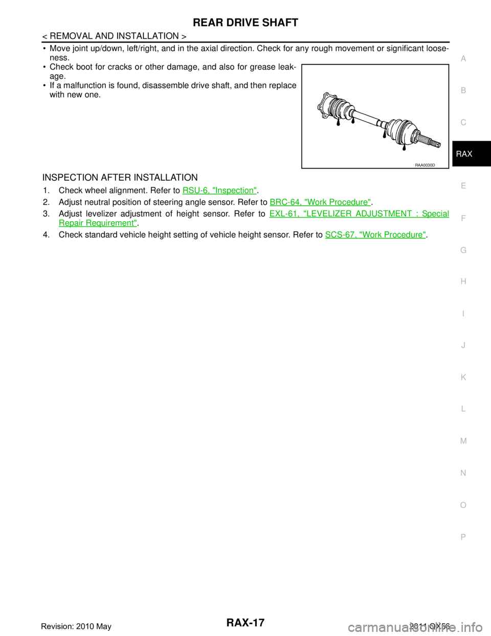
Move joint up/down, left/right, and in the axial directi on. Check for any rough movement or significant loose-
ness.
Check boot for cracks or other damage, and also for grease leak-
age.
If a malfunction is found, disassem ble drive shaft, and then replace
with new one.
INSPECTION AFTER INSTALLATION
1. Check wheel alignment. Refer to RSU-6, "Inspection".
2. Adjust neutral position of steering angle sensor. Refer to BRC-64, "
Work Procedure".
3. Adjust levelizer adjustment of height sensor. Refer to EXL-61, "
LEVELIZER ADJUSTMENT : Special
Repair Requirement".
4. Check standard vehicle height setting of vehicle height sensor. Refer to SCS-67, "
Work Procedure".
RAA0030D
Revision: 2010 May2011 QX56
Page 4256 of 5598
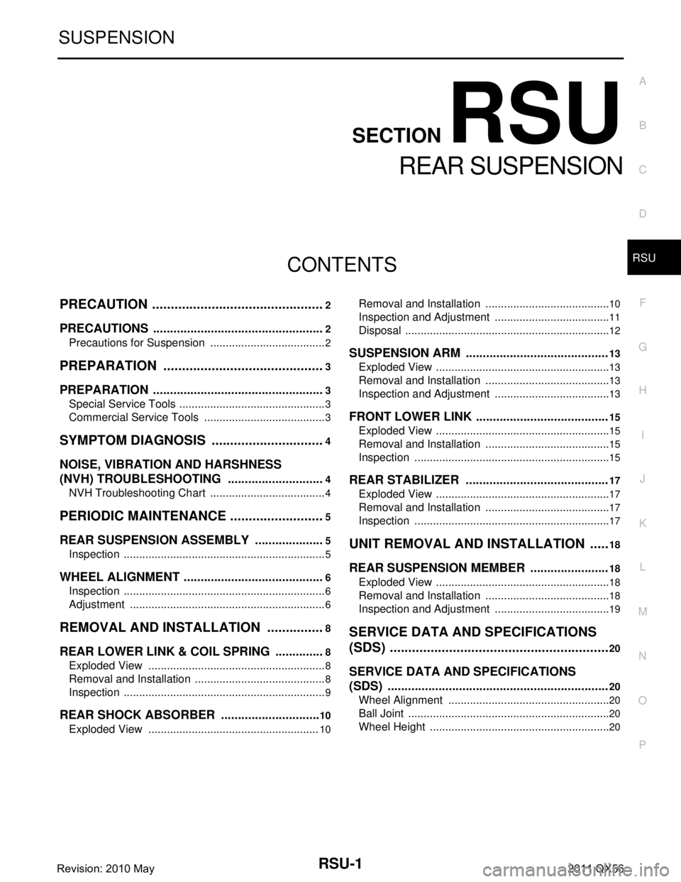
RSU-1
SUSPENSION
C
DF
G H
I
J
K L
M
SECTION RSU
A
B
RSU
N
O PCONTENTS
REAR SUSPENSION
PRECAUTION ................ ...............................2
PRECAUTIONS .............................................. .....2
Precautions for Suspension ................................ ......2
PREPARATION ............................................3
PREPARATION .............................................. .....3
Special Service Tools .......................................... ......3
Commercial Service Tools ........................................3
SYMPTOM DIAGNOSIS ...............................4
NOISE, VIBRATION AND HARSHNESS
(NVH) TROUBLESHOOTING ........................ .....
4
NVH Troubleshooting Chart ................................ ......4
PERIODIC MAINTENANCE ..........................5
REAR SUSPENSION ASSEMBLY ................ .....5
Inspection ............................................................ ......5
WHEEL ALIGNMENT ..........................................6
Inspection ............................................................ ......6
Adjustment ................................................................6
REMOVAL AND INSTALLATION ................8
REAR LOWER LINK & COIL SPRING .......... .....8
Exploded View .................................................... ......8
Removal and Installation ...........................................8
Inspection ..................................................................9
REAR SHOCK ABSORBER ..............................10
Exploded View .................................................... ....10
Removal and Installation ..................................... ....10
Inspection and Adjustment ......................................11
Disposal ...................................................................12
SUSPENSION ARM ..........................................13
Exploded View .........................................................13
Removal and Installation .........................................13
Inspection and Adjustment ......................................13
FRONT LOWER LINK .......................................15
Exploded View .........................................................15
Removal and Installation .........................................15
Inspection ................................................................15
REAR STABILIZER ..........................................17
Exploded View .........................................................17
Removal and Installation .........................................17
Inspection ................................................................17
UNIT REMOVAL AND INSTALLATION ......18
REAR SUSPENSION MEMBER .......................18
Exploded View ..................................................... ....18
Removal and Installation .........................................18
Inspection and Adjustment ......................................19
SERVICE DATA AND SPECIFICATIONS
(SDS) ............... .............................................
20
SERVICE DATA AND SPECIFICATIONS
(SDS) .................................................................
20
Wheel Alignment ................................................. ....20
Ball Joint ..................................................................20
Wheel Height ...........................................................20
Revision: 2010 May2011 QX56
Page 4257 of 5598
RSU-2
< PRECAUTION >
PRECAUTIONS
PRECAUTION
PRECAUTIONS
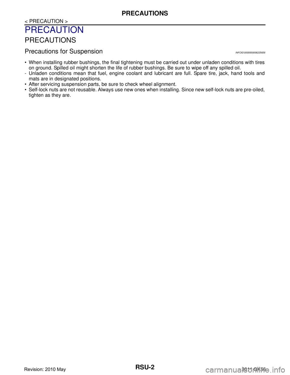
Precautions for SuspensionINFOID:0000000006225656
• When installing rubber bushings, the final tightening must be carried out under unladen conditions with tires
on ground. Spilled oil might shorten the life of rubber bushings. Be sure to wipe off any spilled oil.
- Unladen conditions mean that fuel, engine coolant and l ubricant are full. Spare tire, jack, hand tools and
mats are in designated positions.
After servicing suspension parts, be sure to check wheel alignment.
Self-lock nuts are not reusable. Always use new ones when installing. Since new self-lock nuts are pre-oiled,
tighten as they are.
Revision: 2010 May2011 QX56
Page 4259 of 5598
RSU-4
< SYMPTOM DIAGNOSIS >
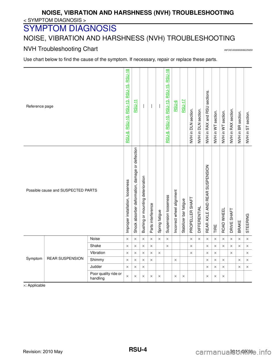
NOISE, VIBRATION AND HARSHNESS (NVH) TROUBLESHOOTING
SYMPTOM DIAGNOSIS
NOISE, VIBRATION AND HARSHNESS (NVH) TROUBLESHOOTING
NVH Troubleshooting ChartINFOID:0000000006225659
Use chart below to find the cause of the symptom. If necessary, repair or replace these parts.
×: ApplicableReference page
RSU-8
,
RSU-10
, RSU-13
, RSU-15
, RSU-18
RSU-11
—
—
—
RSU-8
, RSU-10
, RSU-13
, RSU-15
, RSU-18
RSU-6RSU-17
NVH in DLN section.
NVH in DLN section.
NVH in RAX and RSU sections.
NVH in WT section.
NVH in WT section.
NVH in RAX section.
NVH in BR section.
NVH in ST section.
Possible cause and SUSPECTED PARTS
Improper installation, looseness
Shock absorber deformation, damage or deflection
Bushing or mounting deterioration
Parts interference
Spring fatigue
Suspension looseness
Incorrect wheel alignment
Stabilizer bar fatigue
PROPELLER SHAFT
DIFFERENTIAL
REAR AXLE AND REAR SUSPENSION
TIRE
ROAD WHEEL
DRIVE SHAFT
BRAKE
STEERING
Symptom REAR SUSPENSION Noise
×××××× ××××××××
Shake ×××× × × ××××××
Vibration ××××× × ×× × ×
Shimmy ×××× × ××× ××
Judder ××× ××× ××
Poor quality ride or
handling ××××× ×× ×××
Revision: 2010 May2011 QX56
Page 4261 of 5598
RSU-6
< PERIODIC MAINTENANCE >
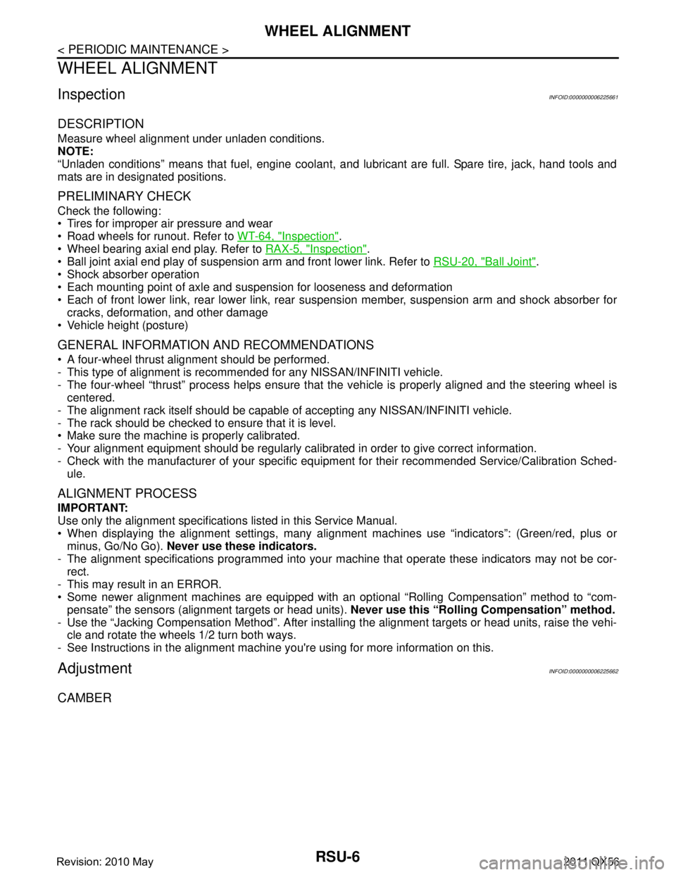
WHEEL ALIGNMENT
WHEEL ALIGNMENT
InspectionINFOID:0000000006225661
DESCRIPTION
Measure wheel alignment under unladen conditions.
NOTE:
“Unladen conditions” means that fuel, engine coolant, and lubricant are full. Spare tire, jack, hand tools and
mats are in designated positions.
PRELIMINARY CHECK
Check the following:
Tires for improper air pressure and wear
Road wheels for runout. Refer to WT-64, "
Inspection".
Wheel bearing axial end play. Refer to RAX-5, "
Inspection".
Ball joint axial end play of suspension arm and front lower link. Refer to RSU-20, "
Ball Joint".
Shock absorber operation
Each mounting point of axle and suspension for looseness and deformation
Each of front lower link, rear lower link, rear suspension member, suspension arm and shock absorber for
cracks, deformation, and other damage
Vehicle height (posture)
GENERAL INFORMATION AND RECOMMENDATIONS
A four-wheel thrust alignment should be performed.
- This type of alignment is recomm ended for any NISSAN/INFINITI vehicle.
- The four-wheel “thrust” process helps ensure that t he vehicle is properly aligned and the steering wheel is
centered.
- The alignment rack itself should be capable of accepting any NISSAN/INFINITI vehicle.
- The rack should be checked to ensure that it is level.
Make sure the machine is properly calibrated.
- Your alignment equipment should be regularly calib rated in order to give correct information.
- Check with the manufacturer of your specific equi pment for their recommended Service/Calibration Sched-
ule.
ALIGNMENT PROCESS
IMPORTANT:
Use only the alignment specifications listed in this Service Manual.
When displaying the alignment settings, many alignment machines use “indicators”: (Green/red, plus or
minus, Go/No Go). Never use these indicators.
- The alignment specifications programmed into your machine that operate these indicators may not be cor-
rect.
- This may result in an ERROR.
Some newer alignment machines are equipped with an optional “Rolling Compensation” method to “com- pensate” the sensors (alignment targets or head units). Never use this “Rolling Compensation” method.
- Use the “Jacking Compensation Method”. After installi ng the alignment targets or head units, raise the vehi-
cle and rotate the wheels 1/2 turn both ways.
- See Instructions in the alignment machine you're using for more information on this.
AdjustmentINFOID:0000000006225662
CAMBER
Revision: 2010 May2011 QX56