2011 INFINITI QX56 tire type
[x] Cancel search: tire typePage 4285 of 5598

SB-10
< REMOVAL AND INSTALLATION >
SECOND SEAT BELT
SECOND SEAT BELT
SEAT BELT RETRACTOR
SEAT BELT RETRACTOR : InspectionINFOID:0000000006217621
AFTER A COLLISION
WARNING:
Inspect all seat belt assemblies including retractors and attached hardware after any collision.
NISSAN/INFINITI recommends that all seat belt assemblies in use during a collision be replaced
unless the collision was minor and th e belts show no damage and continue to operate properly. Fail-
ure to do so could result in seri ous personal injury in an accident. Seat belt assemblies not in use dur-
ing a collision should also be re placed if either damage or improper operation was noted. Seat belt
pre-tensioners should be replaced even if the seat be lts were not in use during a frontal collision in
which the air bags were deployed.
Replace any seat belt assembly (including anchor bolts) if:
The seat belt is in use at the time of a collision (e xcept for minor collisions and the belts, retractors and buck-
les show no damage and continue to operate properly).
The seat belt is damaged in an accident (i.e. to rn webbing, bent retractor or guide, etc.).
The seat belt attaching point is damaged in an accident . Inspect the seat belt attaching area for damage or
distortion and repair if necessary before installing a new seat belt assembly.
Anchor bolts are deformed or worn out.
The seat belt pre-tensioners must be replaced even if t he seat belts were not in use during the collision in
which the air bags were deployed.
PRELIMINARY CHECKS
1. Check that the seat belt retractor, s eat belt anchor and buckle bolts are tightened firmly.
2. Check retractor operation:
a. Fully extend the seat belt webbing and c heck for twists, tears or other damage.
b. Allow the seat belt to retract. Check that webbing retu rns smoothly and completely into the retractor. If the
seat belt does not return smoothly, wipe the inside of the loops with a clean paper cloth. Dirt build-up in the
loops of that upper anchors can cause the seat belts to retract slowly.
c. Fasten the seat belt. Check that seat belt returns sm oothly and completely to the retractor. If the webbing
does not return smoothly, the cause may be an accumulation of dust or dirt. Use the “SEAT BELT TAPE
SET” and perform the following steps.
3. Repeat steps above if necessary to check the other seat belts.
SEAT BELT RETRACTOR ON-VEHICLE CHECK
Emergency Locking Retractors (ELR) and Automatic Locking Retractors (ALR)
NOTE:
All seat belt retractors are Emergency Locking Retr actors (ELR) type. In an emergency (sudden stop) the
retractor will lock and prevent the webbing from extendi ng any further. All 3-point type seat belt retractors
except the driver seat belt also have an Automati c Locking Retractors (ALR) mode. The ALR mode (also
called child restraint mode) is used when installing child seats. The ALR mode is activated when the seat belt
is fully extended. When the webbing is then retracted part ially, the ALR mode automatically locks the seat belt
in a specific position so the webbing cannot be extended any further. To cancel the ALR mode, allow the seat
belt to fully wind back into the retractor.
Check the seat belt retractors with the following test(s ) to determine if a retractor assembly is operating prop-
erly.
ELR Function Stationary Check
Grasp the shoulder webbing and pull forward quickly. T he retractor should lock and prevent the belt from
extending further.
ALR Function Stationary Check
1. Pull out the entire length of seat belt from retractor until a click is heard.
2. Retract the webbing partially. A clicking noise should be heard as the webbing retracts indicating that the retractor is in the Automatic Locking Retractors (ALR) mode.
Revision: 2010 May2011 QX56
Page 4292 of 5598
THIRD SEAT BELTSB-17
< REMOVAL AND INSTALLATION >
C
DE
F
G
I
J
K L
M A
B
SB
N
O P
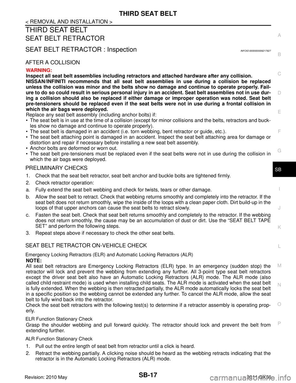
THIRD SEAT BELT
SEAT BELT RETRACTOR
SEAT BELT RETRACTOR : InspectionINFOID:0000000006217627
AFTER A COLLISION
WARNING:
Inspect all seat belt assemblies in cluding retractors and attached hardware after any collision.
NISSAN/INFINITI recommends that all seat belt assemblies in use during a collision be replaced
unless the collision was minor and th e belts show no damage and continue to operate properly. Fail-
ure to do so could result in serious personal inju ry in an accident. Seat belt assemblies not in use dur-
ing a collision should also be replaced if either da mage or improper operation was noted. Seat belt
pre-tensioners should be replaced even if the seat be lts were not in use during a frontal collision in
which the air bags were deployed.
Replace any seat belt assembly (including anchor bolts) if:
The seat belt is in use at the time of a collision (exc ept for minor collisions and the belts, retractors and buck-
les show no damage and continue to operate properly).
The seat belt is damaged in an accident (i.e. to rn webbing, bent retractor or guide, etc.).
The seat belt attaching point is damaged in an accident . Inspect the seat belt attaching area for damage or
distortion and repair if necessary before installing a new seat belt assembly.
Anchor bolts are deformed or worn out.
The seat belt pre-tensioners must be replaced even if t he seat belts were not in use during the collision in
which the air bags were deployed.
PRELIMINARY CHECKS
1. Check that the seat belt retractor, seat belt anchor and buckle bolts are tightened firmly.
2. Check retractor operation:
a. Fully extend the seat belt webbing and check for twists, tears or other damage.
b. Allow the seat belt to retract. Check that webbing retu rns smoothly and completely into the retractor. If the
seat belt does not return smoothly, wipe the inside of t he loops with a clean paper cloth. Dirt build-up in the
loops of that upper anchors can cause the seat belts to retract slowly.
c. Fasten the seat belt. Check that seat belt returns sm oothly and completely to the retractor. If the webbing
does not return smoothly, the cause may be an accu mulation of dust or dirt. Use the “SEAT BELT TAPE
SET” and perform the following steps.
3. Repeat steps above if necessary to check the other seat belts.
SEAT BELT RETRACTOR ON-VEHICLE CHECK
Emergency Locking Retractors (ELR) and Automatic Locking Retractors (ALR)
NOTE:
All seat belt retractors are Emergency Locking Retr actors (ELR) type. In an emergency (sudden stop) the
retractor will lock and prevent the webbing from extendi ng any further. All 3-point type seat belt retractors
except the driver seat belt also have an Automati c Locking Retractors (ALR) mode. The ALR mode (also
called child restraint mode) is used when installing child seats. The ALR mode is activated when the seat belt
is fully extended. When the webbing is then retracted part ially, the ALR mode automatically locks the seat belt
in a specific position so the webbi ng cannot be extended any further. To c ancel the ALR mode, allow the seat
belt to fully wind back into the retractor.
Check the seat belt retractors with the following test(s ) to determine if a retractor assembly is operating prop-
erly.
ELR Function Stationary Check
Grasp the shoulder webbing and pull forward quickly. The retractor should lock and prevent the belt from
extending further.
ALR Function Stationary Check
1. Pull out the entire length of seat bel t from retractor until a click is heard.
2. Retract the webbing partially. A clicking noise should be heard as the webbing retracts indicating that the
retractor is in the Automatic Locking Retractors (ALR) mode.
Revision: 2010 May2011 QX56
Page 4769 of 5598
SR-6
< BASIC INSPECTION >
COLLISION DIAGNOSIS
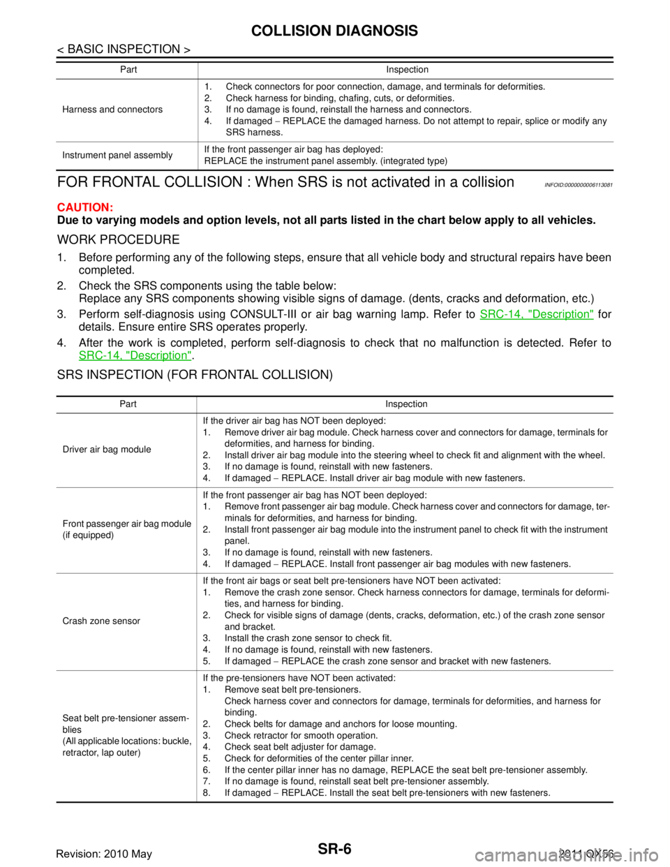
FOR FRONTAL COLLISION : When SRS is not activated in a collision
INFOID:0000000006113081
CAUTION:
Due to varying models and option levels, not all part s listed in the chart below apply to all vehicles.
WORK PROCEDURE
1. Before performing any of the following steps, ensur e that all vehicle body and structural repairs have been
completed.
2. Check the SRS components using the table below: Replace any SRS components showing visible signs of damage. (dents, cracks and deformation, etc.)
3. Perform self-diagnosis using CONSULT-III or air bag warning lamp. Refer to SRC-14, "
Description" for
details. Ensure entire SRS operates properly.
4. After the work is completed, perform self-diagnosis to check that no malfunction is detected. Refer to
SRC-14, "
Description".
SRS INSPECTION (FOR FRONTAL COLLISION)
Harness and connectors 1. Check connectors for poor connection, damage, and terminals for deformities.
2. Check harness for binding, chafing, cuts, or deformities.
3. If no damage is found, reinstall the harness and connectors.
4. If damaged
− REPLACE the damaged harness. Do not attempt to repair, splice or modify any
SRS harness.
Instrument panel assembly If the front passenger air bag has deployed:
REPLACE the instrument panel assembly. (integrated type)
Part Inspection
Part Inspection
Driver air bag module If the driver air bag has NOT been deployed:
1. Remove driver air bag module. Check harness cover and connectors for damage, terminals for
deformities, and harness for binding.
2. Install driver air bag module into the steering wheel to check fit and alignment with the wheel.
3. If no damage is found, reinstall with new fasteners.
4. If damaged − REPLACE. Install driver air bag module with new fasteners.
Front passenger air bag module
(if equipped) If the front passenger air bag has NOT been deployed:
1. Remove front passenger air bag module. Check harness cover and connectors for damage, ter-
minals for deformities, and harness for binding.
2. Install front passenger air bag module into the instrument panel to check fit with the instrument panel.
3. If no damage is found, reinstall with new fasteners.
4. If damaged − REPLACE. Install front passenger air bag modules with new fasteners.
Crash zone sensor If the front air bags or seat belt pre-tensioners have NOT been activated:
1. Remove the crash zone sensor. Check harness connectors for damage, terminals for deformi-
ties, and harness for binding.
2. Check for visible signs of damage (dents, cracks, deformation, etc.) of the crash zone sensor and bracket.
3. Install the crash zone sensor to check fit.
4. If no damage is found, reinstall with new fasteners.
5. If damaged − REPLACE the crash zone sensor and bracket with new fasteners.
Seat belt pre-tensioner assem-
blies
(All applicable locations: buckle,
retractor, lap outer) If the pre-tensioners have NOT been activated:
1. Remove seat belt pre-tensioners.
Check harness cover and connectors for damage , terminals for deformities, and harness for
binding.
2. Check belts for damage and anchors for loose mounting.
3. Check retractor for smooth operation.
4. Check seat belt adjuster for damage.
5. Check for deformities of the center pillar inner.
6. If the center pillar inner has no damage, REPLACE the seat belt pre-tensioner assembly.
7. If no damage is found, reinstall seat belt pre-tensioner assembly.
8. If damaged − REPLACE. Install the seat belt pre-tensioners with new fasteners.
Revision: 2010 May2011 QX56
Page 4799 of 5598
SRC-6
< PRECAUTION >
PRECAUTIONS
PRECAUTION
PRECAUTIONS
Precaution for Supplemental Restraint System (SRS) "AIR BAG" and "SEAT BELT
PRE-TENSIONER"
INFOID:0000000006219946
The Supplemental Restraint System such as “A IR BAG” and “SEAT BELT PRE-TENSIONER”, used along
with a front seat belt, helps to reduce the risk or severi ty of injury to the driver and front passenger for certain
types of collision. This system includes seat belt switch inputs and dual stage front air bag modules. The SRS
system uses the seat belt switches to determine the front air bag deployment, and may only deploy one front
air bag, depending on the severity of a collision and w hether the front occupants are belted or unbelted.
Information necessary to service the system safely is included in the “SRS AIR BAG” and “SEAT BELT” of this
Service Manual.
WARNING:
• To avoid rendering the SRS inopera tive, which could increase the risk of personal injury or death in
the event of a collision that would result in air bag inflation, all maintenance must be performed by
an authorized NISS AN/INFINITI dealer.
Improper maintenance, including in correct removal and installation of the SRS, can lead to personal
injury caused by unintent ional activation of the system. For re moval of Spiral Cable and Air Bag
Module, see the “SRS AIR BAG”.
Do not use electrical test equipmen t on any circuit related to the SRS unless instructed to in this
Service Manual. SRS wiring harnesses can be identi fied by yellow and/or orange harnesses or har-
ness connectors.
PRECAUTIONS WHEN USING POWER TOOLS (AIR OR ELECTRIC) AND HAMMERS
WARNING:
When working near the Air Bag Diagnosis Sensor Unit or other Air Bag System sensors with the ignition ON or engine running, DO NOT use air or electric power tools or strike near the sensor(s)
with a hammer. Heavy vibration could activate the sensor(s) and deploy the air bag(s), possibly
causing serious injury.
When using air or electric power tools or hammers , always switch the ignition OFF, disconnect the
battery, and wait at least 3 minu tes before performing any service.
ServiceINFOID:0000000006219947
Never use electrical test equipment to check SRS circuits unless instructed to in this Service Manual.
Before servicing the SRS, turn ignition switch OF F, disconnect battery negative terminal and wait 3 minutes
or more.
For approximately 3 minutes after the cables are removed, it is still possible for the air bag and seat belt pre-
tensioner to deploy. Therefore, never work on any SR S connectors or wires until at least 3 minutes have
passed.
Diagnosis sensor unit must always be installed with their arrow marks “ ⇐” pointing towards the front of the
vehicle for proper operation. Also chec k diagnosis sensor unit for cracks, deformities or rust before installa-
tion and replace as required.
The spiral cable must be aligned with the neutral position since its rotations are limited. Never turn steering
wheel and column after removal of steering gear.
Handle air bag module carefully. Always place driver and front passenger air bag modules with the pad side facing upward and seat mounted front side air bag module standing with the stud bolt side facing down.
Conduct self-diagnosis to check entire SRS for proper function after replacing any components.
After air bag inflates, the front instrument panel assembly should be replaced if damaged.
Always replace instrument panel pad following front passenger air bag deployment.
Never solder the harness when making repairs. Check that harness is not pinched and that there is no con-
tact with other components.
Never allow harness to come in contact with oil, grease, waste oil, or water.
Never insert foreign materials, such as a screwdriver , into the harness connector. (This is to prevent acci-
dental activation caused by static electricity.)
Always use CONSULT-III or SRS air bag warning lamp to perform the circuit diagnosis. (Never use an elec- tric tester such as a circuit tester.)
Never enter in the deployment area of the pop-up roll bar. Never put an object in the deployment area of the
pop-up roll bar. (This is to prevent injury in case of an unintentional deployment.)
Revision: 2010 May2011 QX56
Page 5029 of 5598
ST-42
< REMOVAL AND INSTALLATION >
STEERING GEAR AND LINKAGE
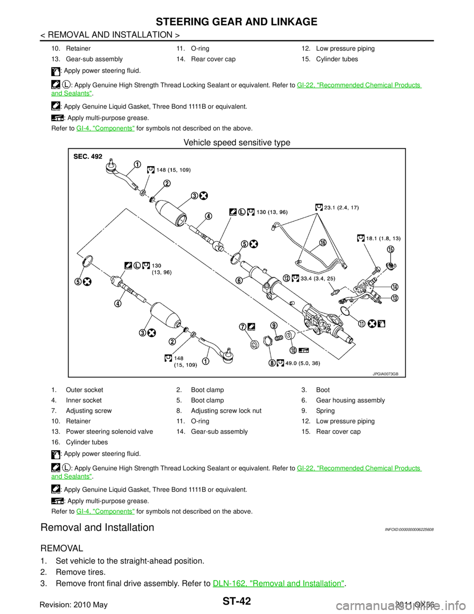
Vehicle speed sensitive type
Removal and InstallationINFOID:0000000006225608
REMOVAL
1. Set vehicle to the straight-ahead position.
2. Remove tires.
3. Remove front final drive assembly. Refer to DLN-162, "
Removal and Installation".
10. Retainer 11. O-ring 12. Low pressure piping
13. Gear-sub assembly 14. Rear cover cap 15. Cylinder tubes
: Apply power steering fluid.
: Apply Genuine High Strength Thread Locking Sealant or equivalent. Refer to GI-22, "
Recommended Chemical Products
and Sealants".
: A p p l y G e n u i n e L i q u i d G a s k e t , T h r e e B o n d 1111 B o r e q u i v a l e n t . : Apply multi-purpose grease.
Refer to GI-4, "
Components" for symbols not described on the above.
JPGIA0073GB
1. Outer socket 2. Boot clamp 3. Boot
4. Inner socket 5. Boot clamp 6. Gear housing assembly
7. Adjusting screw 8. Adjusting screw lock nut 9. Spring
10. Retainer 11. O-ring 12. Low pressure piping
13. Power steering solenoid valve 14. Gear-sub assembly 15. Rear cover cap
16. Cylinder tubes
: Apply power steering fluid.
: Apply Genuine High Strength Thread Locking Sealant or equivalent. Refer to GI-22, "
Recommended Chemical Products
and Sealants".
: A p p l y G e n u i n e L i q u i d G a s k e t , T h r e e B o n d 1111 B o r e q u i v a l e n t . : Apply multi-purpose grease.
Refer to GI-4, "
Components" for symbols not described on the above.
Revision: 2010 May2011 QX56
Page 5454 of 5598
WT-4
< PRECAUTION >
PRECAUTIONS
5. When the repair work is completed, re-connect both battery cables. With the brake pedal released, turn
the push-button ignition switch from ACC position to ON position, then to LOCK position. (The steering
wheel will lock when the push-button igniti on switch is turned to LOCK position.)
6. Perform self-diagnosis check of all control units using CONSULT-III.
Service Notice or Precautions for TPMSINFOID:0000000006225485
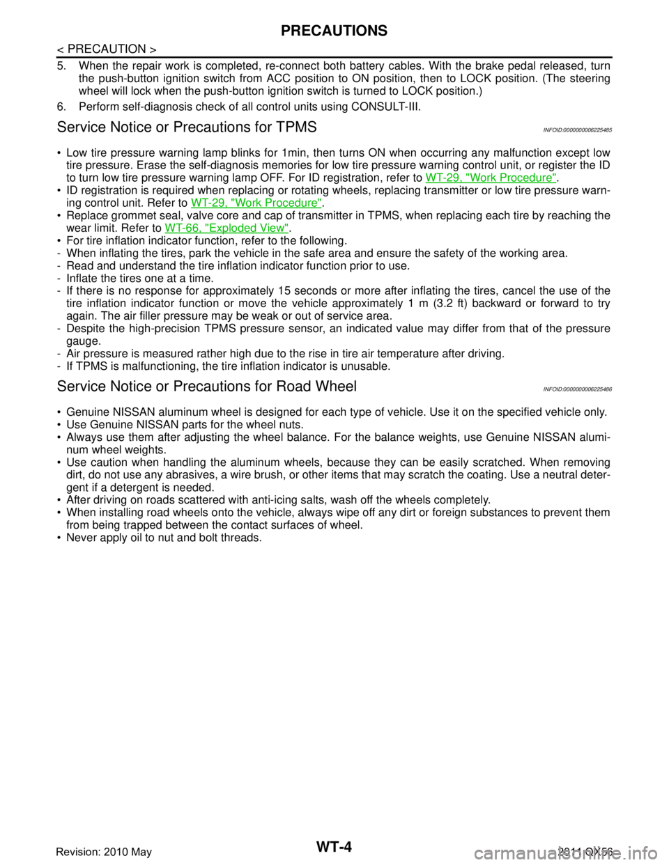
Low tire pressure warning lamp blinks for 1min, then turns ON when occurring any malfunction except low tire pressure. Erase the self-diagnosis memories for low tire pressure warning control unit, or register the ID
to turn low tire pressure warning lamp OFF. For ID registration, refer to WT-29, "
Work Procedure".
ID registration is required when replacing or rotating wheel s, replacing transmitter or low tire pressure warn-
ing control unit. Refer to WT-29, "
Work Procedure".
Replace grommet seal, valve core and cap of transmitter in TPMS, when replacing each tire by reaching the
wear limit. Refer to WT-66, "
Exploded View".
For tire inflation indicator function, refer to the following.
- When inflating the tires, park the vehicle in the safe area and ensure the safety of the working area.
- Read and understand the tire inflation indicator function prior to use.
- Inflate the tires one at a time.
- If there is no response for approximately 15 seconds or mo re after inflating the tires, cancel the use of the
tire inflation indicator function or move the vehicle approximately 1 m (3.2 ft) backward or forward to try
again. The air filler pressure may be weak or out of service area.
- Despite the high-precision TPMS pressure sensor, an i ndicated value may differ from that of the pressure
gauge.
- Air pressure is measured rather high due to the rise in tire air temperature after driving.
- If TPMS is malfunctioning, the tire inflation indicator is unusable.
Service Notice or Precautions for Road WheelINFOID:0000000006225486
Genuine NISSAN aluminum wheel is designed for each type of vehicle. Use it on the specified vehicle only.
Use Genuine NISSAN parts for the wheel nuts.
Always use them after adjusting the wheel balance. For the balance weights, use Genuine NISSAN alumi-
num wheel weights.
Use caution when handling the aluminum wheels, because they can be easily scratched. When removing
dirt, do not use any abrasives, a wire brush, or other it ems that may scratch the coating. Use a neutral deter-
gent if a detergent is needed.
After driving on roads scattered with anti-ici ng salts, wash off the wheels completely.
When installing road wheels onto the vehicle, always wipe of f any dirt or foreign substances to prevent them
from being trapped between the contact surfaces of wheel.
Never apply oil to nut and bolt threads.
Revision: 2010 May2011 QX56
Page 5512 of 5598
WT-62
< PERIODIC MAINTENANCE >
ROAD WHEEL
PERIODIC MAINTENANCE
ROAD WHEEL
AdjustmentINFOID:0000000006225545
BALANCING WHEELS (BONDING WEIGHT TYPE)
Preparation Before Adjustment
Using releasing agent, remove double-faced adhesive tape from the road wheel.
CAUTION:
Be careful not to scratch the road wheel during removal.
After removing double-faced adhesive tape, wi pe clean traces of releasing agent from the road
wheel.
Wheel Balance Adjustment
If a tire balance machine has adhesion balance weight m ode settings and drive-in weight mode setting, select
and adjust a drive-in weight mode suitable for road wheels.
1. Set road wheel on tire balance machine using the center hole as a guide. Start the tire balance machine.
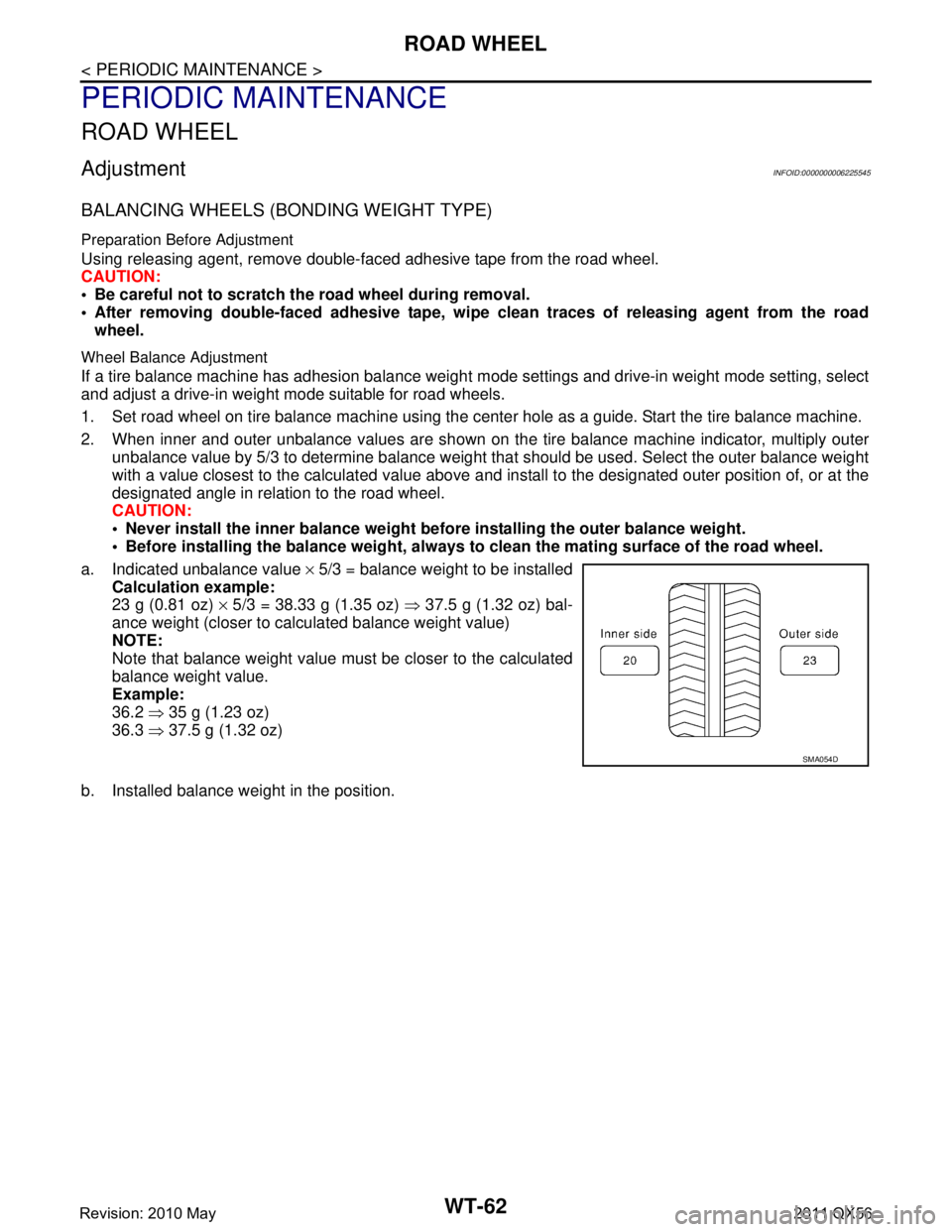
2. When inner and outer unbalance values are shown on the tire balance machine indicator, multiply outer unbalance value by 5/3 to determine balance weight t hat should be used. Select the outer balance weight
with a value closest to the calculated value above and in stall to the designated outer position of, or at the
designated angle in relation to the road wheel.
CAUTION:
Never install the inner balance weight be fore installing the outer balance weight.
Before installing the balance weight, always to clean the mating surface of the road wheel.
a. Indicated unbalance value × 5/3 = balance weight to be installed
Calculation example:
23 g (0.81 oz) × 5/3 = 38.33 g (1.35 oz) ⇒ 37.5 g (1.32 oz) bal-
ance weight (closer to calculated balance weight value)
NOTE:
Note that balance weight value must be closer to the calculated
balance weight value.
Example:
36.2 ⇒ 35 g (1.23 oz)
36.3 ⇒ 37.5 g (1.32 oz)
b. Installed balance weight in the position.
SMA054D
Revision: 2010 May2011 QX56