2011 INFINITI QX56 height
[x] Cancel search: heightPage 1307 of 5598
![INFINITI QX56 2011 Factory Service Manual
DAS-342
< BASIC INSPECTION >[LDW & LDP]
CAMERA AIMING ADJUSTMENT
3. Mark point “E” on the line “LH” at the
positions 3850 mm (151.57 in) from point “A”.
4. Draw line “RH” passing thr INFINITI QX56 2011 Factory Service Manual
DAS-342
< BASIC INSPECTION >[LDW & LDP]
CAMERA AIMING ADJUSTMENT
3. Mark point “E” on the line “LH” at the
positions 3850 mm (151.57 in) from point “A”.
4. Draw line “RH” passing thr](/manual-img/42/57033/w960_57033-1306.png)
DAS-342
< BASIC INSPECTION >[LDW & LDP]
CAMERA AIMING ADJUSTMENT
3. Mark point “E” on the line “LH” at the
positions 3850 mm (151.57 in) from point “A”.
4. Draw line “RH” passing through points “C” and “D” on the right side of vehicle in the same way as step 2. NOTE:
Approximately 4 m (13.12 ft) or more from the front end of vehicle.
5. Mark point “F” on the line “RH” at the positions 3850 mm (151.57 in) from point “C”.
6. Draw line “FW” passing through the points “E” and “F” on the front side of vehicle.
7. Mark point “X” at the center of point “E” and “F” on the line “FW”.
CAUTION:
Make sure that “E” to “X” is equal to “F” to “X”.
8. Position the center of the ri ght target to point of “X”.
>> Go to DAS-342, "
Work Procedure (Camera Aiming
Adjustment)".
Work Procedure (Camera Aiming Adjustment)INFOID:0000000006223737
CAUTION:
Perform the adjustment under unloaded vehicle condition.
1.CHECK VEHICLE HEIGHT
Measure the wheelarch height. Calculate “Dh”.
NOTE:
“Dh” may be calculated as a minus value.
>> GO TO 2.
2.CAMERA AIMING ADJUSTMENT
CAUTION:
Operate CONSULT-III outside the vehic le, and close all the doors. (To retain vehicle attitude appropri-
ately)
1. Select “Work Support” on “L ANE CAMERA” with CONSULT-III.
2. Select “AUTO AIM”.
3. Confirm the following items;
- The target should be accurately placed.
- The vehicle should be stopped.
4. Select “Start” to perform camera aiming. CAUTION:
Never select “Start” when the target is not accurately placed.
Wait 5 seconds or more after selecting “Start”.
5. Input “Dh”, and then select “Start”.
CAUTION:
Never change “Ht” and “Dt”.
6. Confirm the displayed item.
- “Normally Completed”: Select “Completion”.
- “SUSPENSION”, “X AIMING NG Y”, “ABNORMALL Y COMPLETED”: Perform the following services.
JPOIA0173GB
Dh [mm] = (Hfl + Hfr) ÷ 2 − 903
where, Hfl: Front left wheelarch height [mm]
Hfr: Front right wh eelarch height [mm]
JSOIA0361ZZ
Revision: 2010 May2011 QX56
Page 1753 of 5598
HOOD
DLK-217
< REMOVAL AND INSTALLATION >
C
D E
F
G H
I
J
L
M A
B
DLK
N
O P
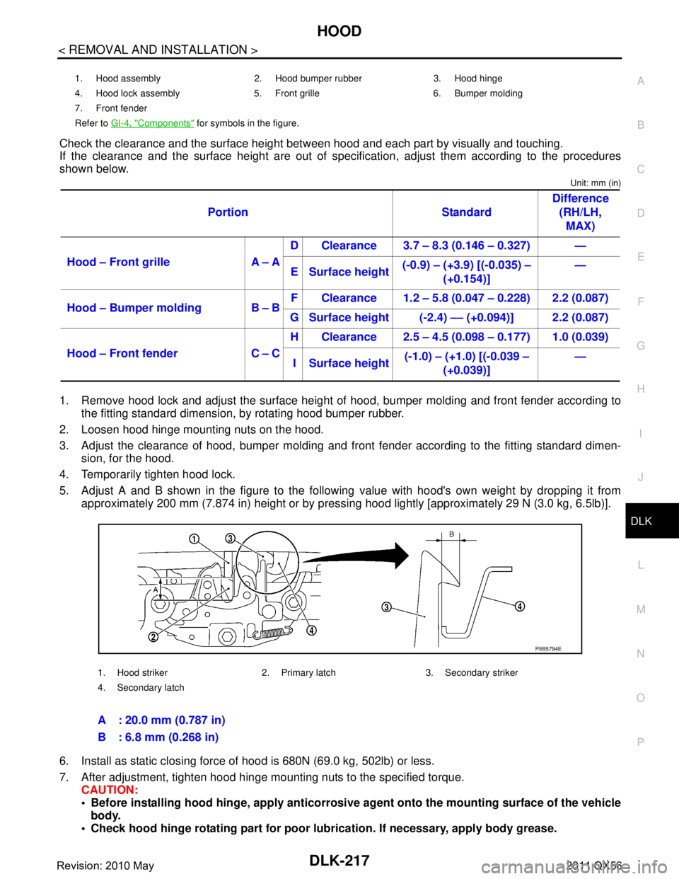
Check the clearance and the surface height betw een hood and each part by visually and touching.
If the clearance and the surface height are out of spec ification, adjust them according to the procedures
shown below.
Unit: mm (in)
1. Remove hood lock and adjust the surface height of hood, bumper molding and front fender according to
the fitting standard dimension, by rotating hood bumper rubber.
2. Loosen hood hinge mounting nuts on the hood.
3. Adjust the clearance of hood, bumper molding and fr ont fender according to the fitting standard dimen-
sion, for the hood.
4. Temporarily tighten hood lock.
5. Adjust A and B shown in the figure to the following value with hood's own weight by dropping it from approximately 200 mm (7.874 in) height or by pressi ng hood lightly [approximately 29 N (3.0 kg, 6.5lb)].
6. Install as static closing force of hood is 680N (69.0 kg, 502lb) or less.
7. After adjustment, tighten hood hinge mounting nuts to the specified torque. CAUTION:
Before installing hood hinge, apply anticorrosive agent onto th e mounting surface of the vehicle
body.
Check hood hinge rotating pa rt for poor lubrication. If necessary, apply body grease.
1. Hood assembly 2. Hood bumper rubber 3. Hood hinge
4. Hood lock assembly 5. Front grille 6. Bumper molding
7. Front fender
Refer to GI-4, "
Components" for symbols in the figure.
Portion Standard Difference
(RH/LH, MAX)
Hood – Front grille A – A D Clearance 3.7 – 8.3 (0.146 – 0.327) —
E Surface height (-0.9) – (+3.9) [(-0.035) –
(+0.154)] —
Hood – Bumper molding B – B F Clearance 1.2 – 5.8 (0.047 – 0.228) 2.2 (0.087)
G Surface height (-2.4) –– (+0.094)] 2.2 (0.087)
Hood – Front fender C – C H Clearance 2.5 – 4.5 (0.098 – 0.177) 1.0 (0.039)
I Surface height (-1.0) – (+1.0) [(-0.039 –
(+0.039)] —
1. Hood striker 2. Primary latch 3. Secondary striker
4. Secondary latch
A : 20.0 mm (0.787 in)
B : 6.8 mm (0.268 in)
PIIB5794E
Revision: 2010 May2011 QX56
Page 1761 of 5598
FRONT DOORDLK-225
< REMOVAL AND INSTALLATION >
C
DE
F
G H
I
J
L
M A
B
DLK
N
O P
DOOR ASSEMBLY : AdjustmentINFOID:0000000006226076
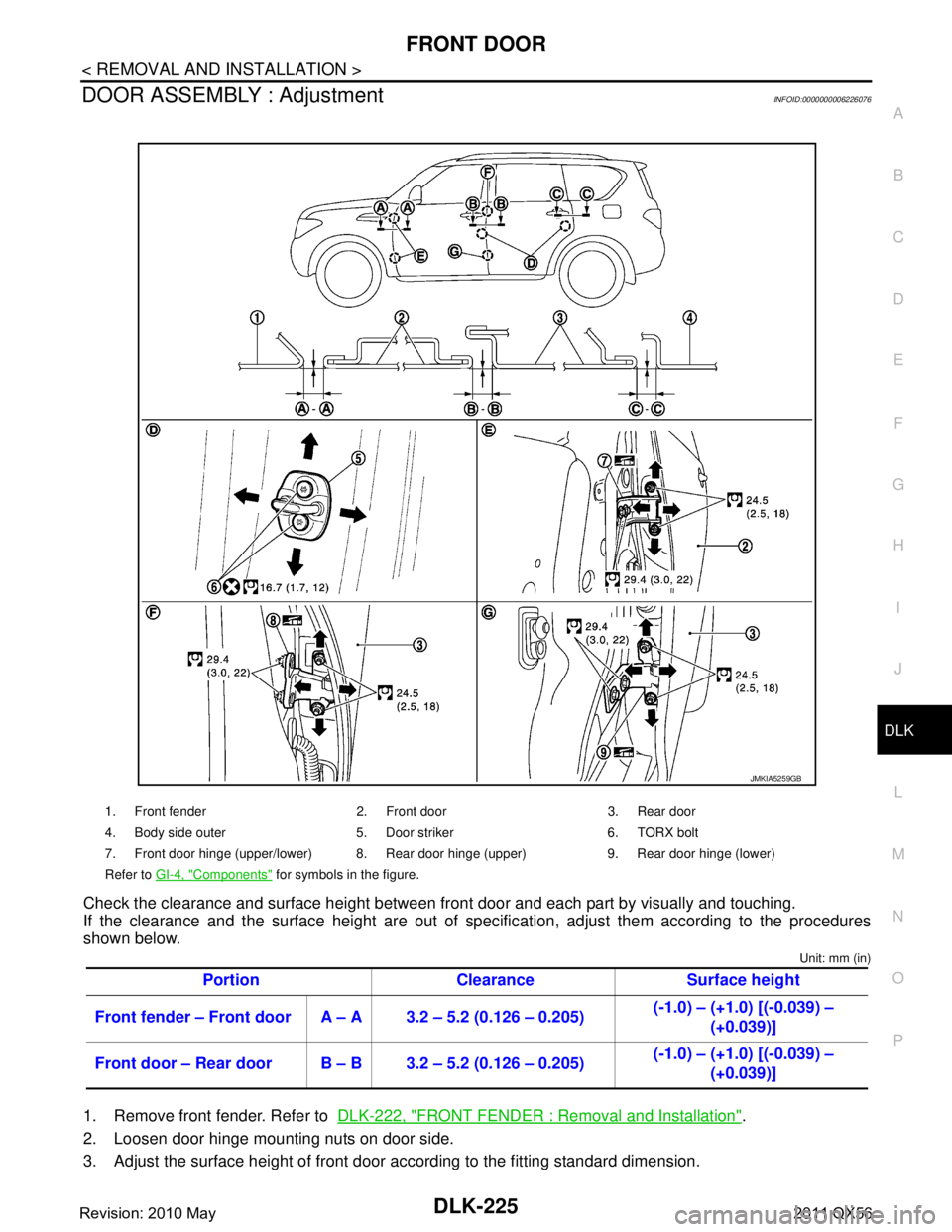
Check the clearance and surface height between front door and each part by visually and touching.
If the clearance and the surface height are out of spec ification, adjust them according to the procedures
shown below.
Unit: mm (in)
1. Remove front fender. Refer to DLK-222, "FRONT FENDER : Removal and Installation".
2. Loosen door hinge mounting nuts on door side.
3. Adjust the surface height of front door according to the fitting standard dimension.
1. Front fender 2. Front door 3. Rear door
4. Body side outer 5. Door striker 6. TORX bolt
7. Front door hinge (upper/lower) 8. Rear door hinge (upper) 9. Rear door hinge (lower)
Refer to GI-4, "
Components" for symbols in the figure.
Portion Clearance Surface height
Front fender – Front door A – A 3.2 – 5.2 (0.126 – 0.205) (-1.0) – (+1.0) [(-0.039) –
(+0.039)]
Front door – Rear door B – B 3.2 – 5.2 (0.126 – 0.205) (-1.0) – (+1.0) [(-0.039) –
(+0.039)]
JMKIA5259GB
Revision: 2010 May2011 QX56
Page 1765 of 5598
REAR DOORDLK-229
< REMOVAL AND INSTALLATION >
C
DE
F
G H
I
J
L
M A
B
DLK
N
O P
After installation, perform th e fitting adjustment. Refer to DLK-229, "DOOR ASSEMBLY : Adjust-
ment".
After installation, apply touch-up paint (the body color) onto the head of door hinge mounting nuts.
DOOR ASSEMBLY : AdjustmentINFOID:0000000006226082
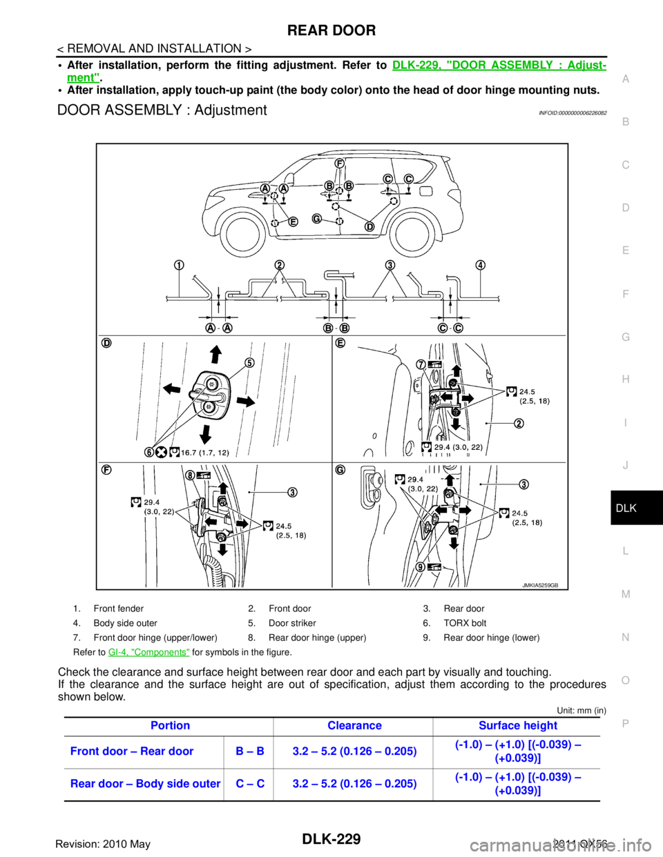
Check the clearance and surface height between rear door and each part by visually and touching.
If the clearance and the surface height are out of spec ification, adjust them according to the procedures
shown below.
Unit: mm (in)
1. Front fender 2. Front door 3. Rear door
4. Body side outer 5. Door striker 6. TORX bolt
7. Front door hinge (upper/lower) 8. Rear door hinge (upper) 9. Rear door hinge (lower)
Refer to GI-4, "
Components" for symbols in the figure.
Portion Clearance Surface height
Front door – Rear door B – B 3.2 – 5.2 (0.126 – 0.205) (-1.0) – (+1.0) [(-0.039) –
(+0.039)]
Rear door – Body side outer C – C 3.2 – 5.2 (0.126 – 0.205) (-1.0) – (+1.0) [(-0.039) –
(+0.039)]
JMKIA5259GB
Revision: 2010 May2011 QX56
Page 1766 of 5598
DLK-230
< REMOVAL AND INSTALLATION >
REAR DOOR
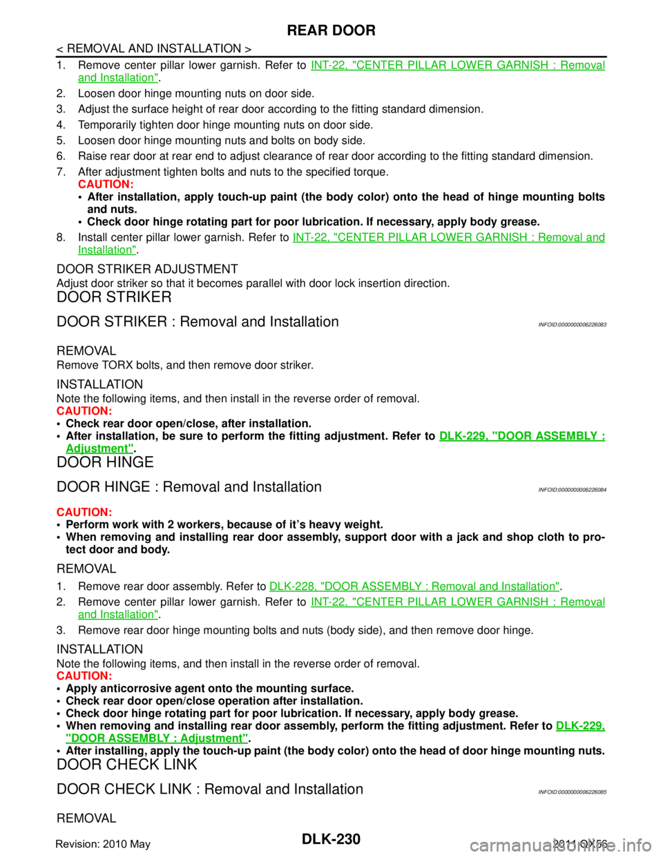
1. Remove center pillar lower garnish. Refer to INT-22, "CENTER PILLAR LOWER GARNISH : Removal
and Installation".
2. Loosen door hinge mounting nuts on door side.
3. Adjust the surface height of rear door according to the fitting standard dimension.
4. Temporarily tighten door hinge mounting nuts on door side.
5. Loosen door hinge mounting nuts and bolts on body side.
6. Raise rear door at rear end to adjust clearance of rear door according to the fitting standard dimension.
7. After adjustment tighten bolts and nuts to the specified torque. CAUTION:
After installation, apply touch-up paint (the bo dy color) onto the head of hinge mounting bolts
and nuts.
Check door hinge rotating part for poor lubrication. If necessary, apply body grease.
8. Install center pillar lower garnish. Refer to INT-22, "
CENTER PILLAR LOWER GARNISH : Removal and
Installation".
DOOR STRIKER ADJUSTMENT
Adjust door striker so that it becomes parallel with door lock insertion direction.
DOOR STRIKER
DOOR STRIKER : Removal and InstallationINFOID:0000000006226083
REMOVAL
Remove TORX bolts, and then remove door striker.
INSTALLATION
Note the following items, and then install in the reverse order of removal.
CAUTION:
Check rear door open/c lose, after installation.
After installation, be sure to perf orm the fitting adjustment. Refer to DLK-229, "
DOOR ASSEMBLY :
Adjustment".
DOOR HINGE
DOOR HINGE : Removal and InstallationINFOID:0000000006226084
CAUTION:
Perform work with 2 workers, because of it’s heavy weight.
When removing and installing r ear door assembly, support door with a jack and shop cloth to pro-
tect door and body.
REMOVAL
1. Remove rear door assembly. Refer to DLK-228, "DOOR ASSEMBLY : Removal and Installation".
2. Remove center pillar lower garnish. Refer to INT-22, "
CENTER PILLAR LOWER GARNISH : Removal
and Installation".
3. Remove rear door hinge mounting bolts and nuts (body side), and then remove door hinge.
INSTALLATION
Note the following items, and then install in the reverse order of removal.
CAUTION:
Apply anticorrosive agent onto the mounting surface.
Check rear door open/close op eration after installation.
Check door hinge rotating pa rt for poor lubrication. If necessary, apply body grease.
When removing and inst alling rear door assembly, perform the fitting adjustment. Refer to DLK-229,
"DOOR ASSEMBLY : Adjustment".
After installing, apply the touch-up paint (the body color) onto the head of door hinge mounting nuts.
DOOR CHECK LINK
DOOR CHECK LINK : Removal and InstallationINFOID:0000000006226085
REMOVAL
Revision: 2010 May2011 QX56
Page 1770 of 5598
DLK-234
< REMOVAL AND INSTALLATION >
BACK DOOR
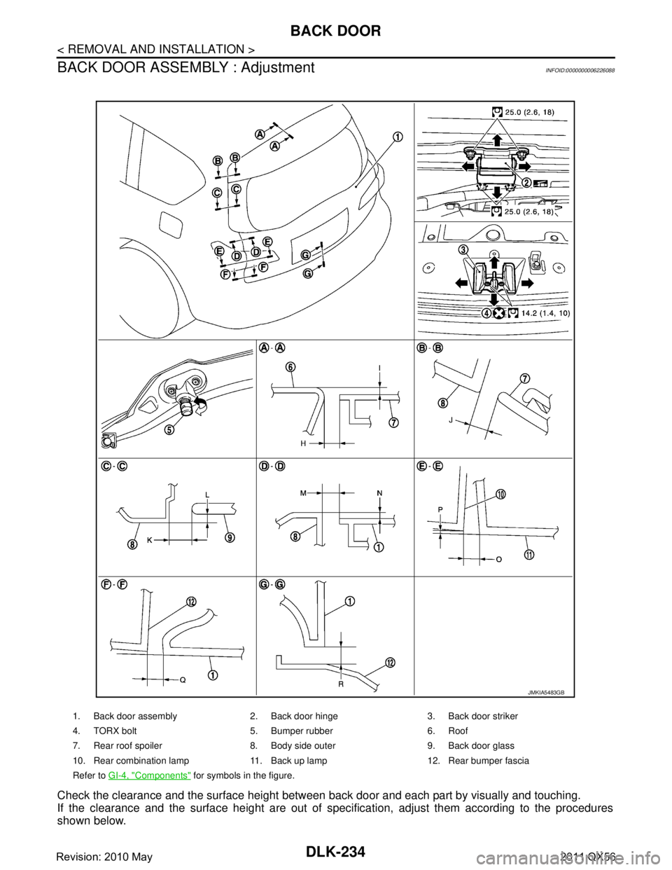
BACK DOOR ASSEMBLY : Adjustment
INFOID:0000000006226088
Check the clearance and the surface height between back door and each part by visually and touching.
If the clearance and the surface height are out of spec ification, adjust them according to the procedures
shown below.
1. Back door assembly 2. Back door hinge 3. Back door striker
4. TORX bolt 5. Bumper rubber 6. Roof
7. Rear roof spoiler 8. Body side outer 9. Back door glass
10. Rear combination lamp 11. Back up lamp 12. Rear bumper fascia
Refer to GI-4, "
Components" for symbols in the figure.
JMKIA5483GB
Revision: 2010 May2011 QX56
Page 1771 of 5598
BACK DOORDLK-235
< REMOVAL AND INSTALLATION >
C
DE
F
G H
I
J
L
M A
B
DLK
N
O P
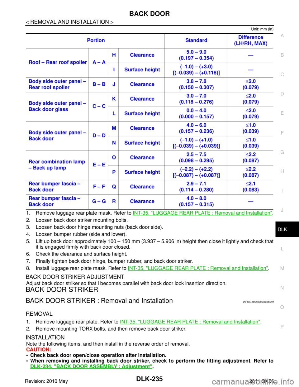
Unit: mm (in)
1. Remove luggage rear plate mask. Refer to INT-35, "LUGGAGE REAR PLATE : Removal and Installation".
2. Loosen back door striker mounting bolts.
3. Loosen back door hinge mounting nuts (back door side).
4. Loosen bumper rubber (side and lower).
5. Lift up back door approximately 100 – 150 mm (3.937 – 5.906 in) height then close it lightly and check that
it is engaged firmly with back door closed.
6. Check the clearance and surface height.
7. Finally tighten back door hinge, bumper rubber, and back door striker.
8. Install luggage rear plate mask. Refer to INT-35, "
LUGGAGE REAR PLATE : Removal and Installation".
BACK DOOR STRIKER ADJUSTMENT
Adjust back door striker so that i becomes parallel with back door lock insertion direction.
BACK DOOR STRIKER
BACK DOOR STRIKER : Removal and InstallationINFOID:0000000006226089
REMOVAL
1. Remove luggage rear plate. Refer to INT-35, "LUGGAGE REAR PLATE : Removal and Installation".
2. Remove mounting TORX bolts, and then remove back door striker.
INSTALLATION
Note the following items, and then install in the reverse order of removal.
CAUTION:
Check back door open/close ope ration after installation.
When removing and installing b ack door striker, check to perform th e fitting adjustment. Refer to
DLK-234, "
BACK DOOR ASSEMBLY : Adjustment".
Portion Standard
Difference
(LH/RH, MAX)
Roof – Rear roof spoiler A – A H Clearance
5.0 – 9.0
(0.197 – 0.354) —
I Surface height (
− 1.0) – (+3.0)
[( −0.039) – (+0.118)] —
Body side outer panel –
Rear roof spoiler B – B J Clearance 3.8 – 7.8
(0.150 – 0.307) ≤
2.0
(0.079)
Body side outer panel –
Back door glass C – CK Clearance
3.0 – 7.0
(0.118 – 0.276) ≤
2.0
(0.079)
L Surface height 0.0 – 4.0
(0.000 – 0.157) ≤
2.0
(0.079)
Body side outer panel –
Back door D – DM Clearance
4.0 – 6.0
(0.157 – 0.236) ≤
1.0
(0.039)
N Surface height (
− 1.0) – (+1.0)
[( −0.039) – (+0.039)] ≤
1.0
(0.039)
Rear combination lamp
– Back up lamp E – EO Clearance
2.5 – 7.5
(0.098 – 0.295) ≤
2.2
(0.087)
P Surface height (
− 2.2) – (+2.2)
[( −0.087) – (+0.087)] ≤
2.2
(0.087)
Rear bumper fascia –
Back door F – F Q Clearance 2.9 – 7.1
(0.114 – 0.280) ≤
2.1
(0.083)
Rear bumper fascia –
Back door G – G R Clearance 4.0 – 8.0
(0.157 – 0.315) —
Revision: 2010 May2011 QX56
Page 1953 of 5598
![INFINITI QX56 2011 Factory Service Manual
PREPARATIONDLN-151
< PREPARATION > [FRONT FINAL DRIVE: R180A]
C
EF
G H
I
J
K L
M A
B
DLN
N
O P
Commercial Service ToolINFOID:0000000006222375
ST30901000
(J-26010-01)
Drift
a: 79 mm (3.11 in) dia.
b: INFINITI QX56 2011 Factory Service Manual
PREPARATIONDLN-151
< PREPARATION > [FRONT FINAL DRIVE: R180A]
C
EF
G H
I
J
K L
M A
B
DLN
N
O P
Commercial Service ToolINFOID:0000000006222375
ST30901000
(J-26010-01)
Drift
a: 79 mm (3.11 in) dia.
b:](/manual-img/42/57033/w960_57033-1952.png)
PREPARATIONDLN-151
< PREPARATION > [FRONT FINAL DRIVE: R180A]
C
EF
G H
I
J
K L
M A
B
DLN
N
O P
Commercial Service ToolINFOID:0000000006222375
ST30901000
(J-26010-01)
Drift
a: 79 mm (3.11 in) dia.
b: 45 mm (1.77 in) dia.
c: 35.2 mm (1.386 in) dia. Installing drive pinion rear bearing inner race
ST33200000
(J-26082)
Drift
a: 60 mm (2.36 in) dia.
b: 44.5 mm (1.752 in) dia. Installing drive pinion front bearing inner race
—
(J-34309)
Differential shim selector tool Adjusting bearing preload and pinion gear
height
—
(J-25269-18)
Side bearing disc (2 Req ′d) Selecting pinion height adjusting washer
Tool number
(Kent-Moore No.)
Tool name
Description
ZZA0978D
ZZA1002D
NT134
NT135
Tool name
Description
Power tool Loosening bolts and nuts
Flange wrench Removing and installing drive pinion lock nut
PBIC0190E
NT035
Revision: 2010 May2011 QX56