2011 INFINITI QX56 checking oil
[x] Cancel search: checking oilPage 3068 of 5598

HA-12
< PREPARATION >
PREPARATION
Commercial Service Tool
INFOID:0000000006276518
Sealant or/and LubricantINFOID:0000000006276143
HFC-134a (R-134a) Service Tool and Equipment
Never mix HFC-134a (R-134a) refrigerant and/or its s pecified lubricant with CFC-12 (R-12) refrigerant and/
or its lubricant.
Separate and non-interchangeable service equipment must be used for handling each type of refrigerant/ lubricant.
Refrigerant container fittings, service hose fittings and service equipment fittings (equipment which handles
refrigerant and/or lubricant) are different between CF C-12 (R-12) and HFC-134a (R-134a). This is to avoid
mixed use of the refrigerants/lubricant.
Never use adapters that convert one size fitting to another: refrigerant/lubricant contamination occurs and
compressor malfunction may result.
Tool name Description
Refrigerant identifier equipment Checking for refrigerant purity and
system contamination
Power tools For loosening bolts and nuts
RJIA0197E
PBIC0190E
Tool name Description
HFC-134a (R-134a) refrigerant Container color: Light blue
Container marking: HFC-134a (R-
134a)
Fitting size: Thread size
Large container 1/2
″-16 ACME
A/C System Oil Type S (DH-PS) Type: Polyalkylene glycol oil (PAG),
type S (DH-PS)
Application:
HFC-134a (R-134a) swash plate com-
pressors
Capacity: 40 m (1.4 Imp fl oz.)
S-NT196
S-NT197
Revision: 2010 May2011 QX56
Page 3085 of 5598
NOISEHA-29
< SYMPTOM DIAGNOSIS >
C
DE
F
G H
J
K L
M A
B
HA
N
O P
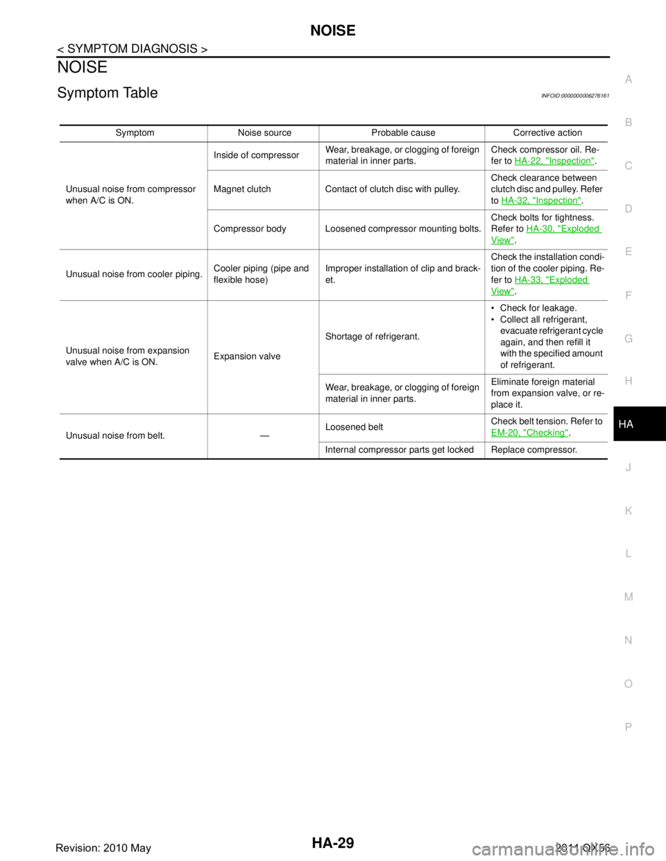
NOISE
Symptom TableINFOID:0000000006276161
Symptom Noise source Probable cause Corrective action
Unusual noise from compressor
when A/C is ON. Inside of compressor
Wear, breakage, or clogging of foreign
material in inner parts. Check compressor oil. Re-
fer to
HA-22, "
Inspection".
Magnet clutch Contact of clutch disc with pulley. Check clearance between
clutch disc and pulley. Refer
to
HA-32, "
Inspection".
Compressor body Loosened compressor mounting bolts. Check bolts for tightness.
Refer to
HA-30, "
Exploded
View".
Unusual noise from cooler piping. Cooler piping (pipe and
flexible hose)Improper installation of clip and brack-
et. Check the installation condi-
tion of the cooler piping. Re-
fer to
HA-33, "
Exploded
View".
Unusual noise from expansion
valve when A/C is ON. Expansion valveShortage of refrigerant. Check for leakage.
Collect all refrigerant,
evacuate refrigerant cycle
again, and then refill it
with the specified amount
of refrigerant.
Wear, breakage, or clogging of foreign
material in inner parts. Eliminate foreign material
from expansion valve, or re-
place it.
Unusual noise from belt. — Loosened belt
Check belt tension. Refer to
EM-20, "
Checking".
Internal compressor parts ge t locked Replace compressor.
Revision: 2010 May2011 QX56
Page 3087 of 5598
COMPRESSORHA-31
< REMOVAL AND INSTALLATION >
C
DE
F
G H
J
K L
M A
B
HA
N
O P
Perform lubricant return operati on before each refrigeration system disassembly. However, if a large
amount of refrigerant or lubricant is detected, n ever perform lubricant return operation. Refer to HA-
22, "Perform Lubricant Return Operation".
REMOVAL
1. Use a refrigerant collecting equipment (for HF C-134a) to discharge the refrigerant. Refer to HA-20, "Recy-
cle Refrigerant".
2. Remove air cleaner. Refer to EM-27, "
Removal and Installation".
3. Remove mounting bolts, and then disconnect low-pressure flexible hose and high-pressure flexible hose from the compressor.
CAUTION:
Cap or wrap the joint of the A/C piping and comp ressor with suitable material such as vinyl tape to
avoid the entry of air.
4. Remove front under cover. Refer to EXT-25, "
Exploded View".
5. Remove drive belt. Refer to EM-20, "
Removal and Installation".
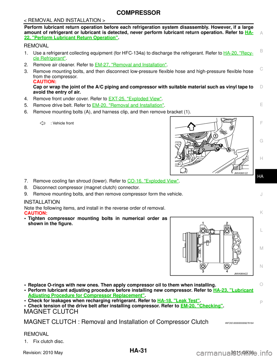
6. Remove mounting bolts (A), and harness clip, and then remove bracket (1).
7. Remove cooling fan shroud (lower). Refer to CO-16, "
Exploded View".
8. Disconnect compressor (magnet clutch) connector.
9. Remove mounting bolts, and then remove compressor form the vehicle.
INSTALLATION
Note the following items, and install in the reverse order of removal.
CAUTION:
Tighten compressor mounting bolts in numerical order as shown in the figure.
Replace O-rings with new ones. Then apply compressor oil to them when installing.
Perform lubricant adjusting procedure befo re installing new compressor. Refer to HA-23, "
Lubricant
Adjusting Procedure for Compressor Replacement".
Check for leakages when recharging refrigerant. Refer to HA-18, "
Leak Test".
Check tension of the drive belt afte r installing compressor. Refer to EM-20, "
Checking".
MAGNET CLUTCH
MAGNET CLUTCH : Removal and Inst allation of Compressor ClutchINFOID:0000000006276164
REMOVAL
1. Fix clutch disc.
: Vehicle front
JMIIA0681ZZ
JMIIA0804ZZ
Revision: 2010 May2011 QX56
Page 3660 of 5598
ENGINE OILLU-7
< PERIODIC MAINTENANCE >
C
DE
F
G H
I
J
K L
M A
LU
NP
O
PERIODIC MAINTENANCE
ENGINE OIL
InspectionINFOID:0000000006289616
OIL LEVEL
NOTE:
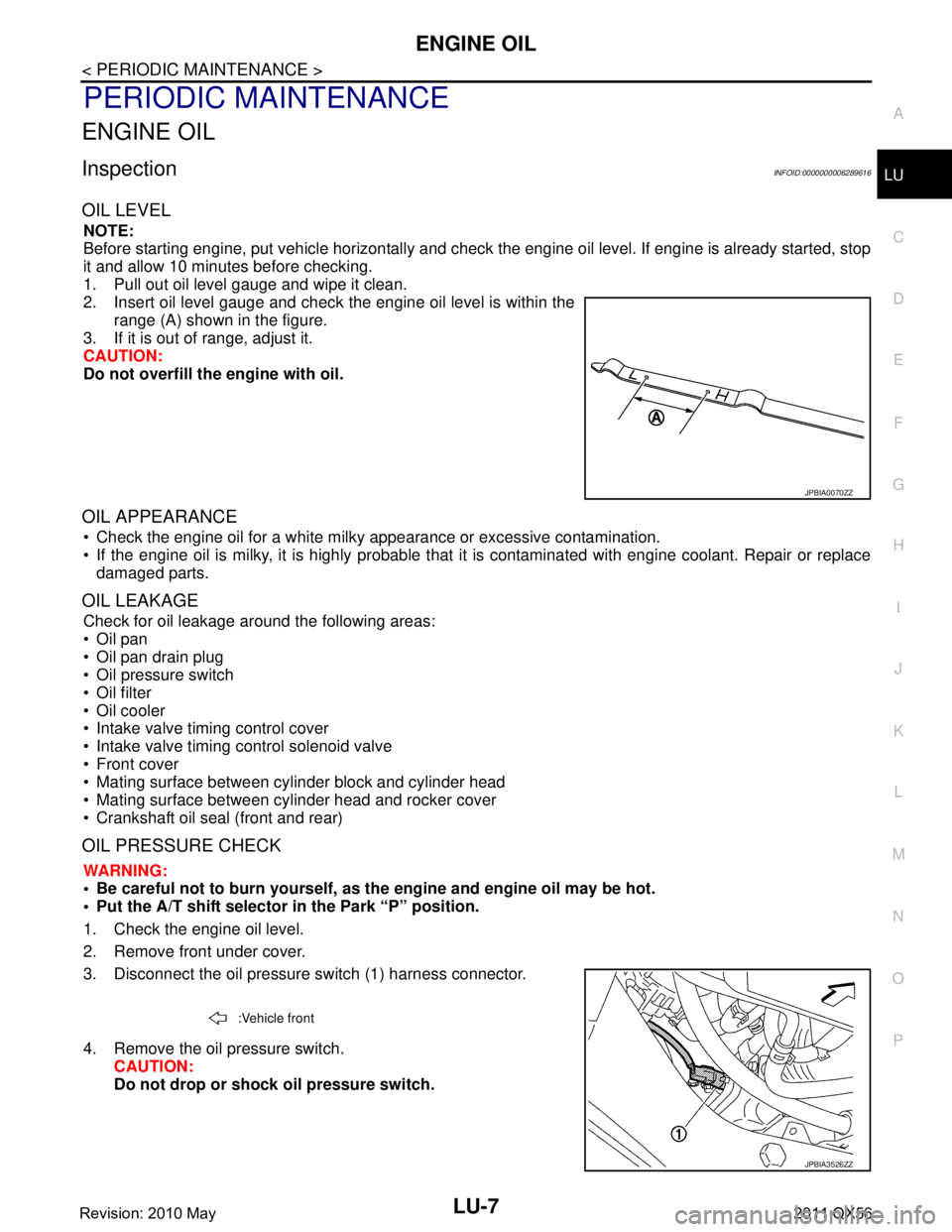
Before starting engine, put vehicle horizontally and check
the engine oil level. If engine is already started, stop
it and allow 10 minutes before checking.
1. Pull out oil level gauge and wipe it clean.
2. Insert oil level gauge and check the engine oil level is within the range (A) shown in the figure.
3. If it is out of range, adjust it.
CAUTION:
Do not overfill the engine with oil.
OIL APPEARANCE
Check the engine oil for a white milky appearance or excessive contamination.
If the engine oil is milky, it is highly probable that it is contaminated with engine coolant. Repair or replace
damaged parts.
OIL LEAKAGE
Check for oil leakage around the following areas:
Oil pan
Oil pan drain plug
Oil pressure switch
Oil filter
Oil cooler
Intake valve timing control cover
Intake valve timing control solenoid valve
Front cover
Mating surface between cylinder block and cylinder head
Mating surface between cylinder head and rocker cover
Crankshaft oil seal (front and rear)
OIL PRESSURE CHECK
WARNING:
• Be careful not to burn yourself, as th e engine and engine oil may be hot.
Put the A/T shift selector in the Park “P” position.
1. Check the engine oil level.
2. Remove front under cover.
3. Disconnect the oil pressure switch (1) harness connector.
4. Remove the oil pressure switch. CAUTION:
Do not drop or shock oil pressure switch.
JPBIA0070ZZ
:Vehicle front
JPBIA3526ZZ
Revision: 2010 May2011 QX56
Page 3671 of 5598
MA-1
MAINTENANCE
C
DE
F
G H
I
J
K L
M B
MA
SECTION MA
N
O A
CONTENTS
MAINTENANCE
PREPARATION .............
...............................3
PREPARATION .............................................. .....3
Special Service Tool ........................................... ......3
Commercial Service Tool ..........................................3
PERIODIC MAINTENANCE ..........................4
GENERAL MAINTENANCE ........................... .....4
Explanation of General Maintenance .................. ......4
PERIODIC MAINTENANCE ................................6
Introduction of Periodic Maintenance .................. ......6
Schedule 1 ................................................................6
Schedule 2 ................................................................8
RECOMMENDED FLUIDS AND LUBRI-
CANTS ................................................................
10
Fluids and Lubricants .......................................... ....10
Engine Oil Recommendation ..................................10
Anti-Freeze Coolant Mixture Ratio ..........................11
ENGINE MAINTENANCE ...................................12
DRIVE BELTS ....................................................... ....12
DRIVE BELTS : Exploded View ..............................12
DRIVE BELTS : Checking .......................................12
DRIVE BELTS : Tension Adjustment .....................12
ENGINE COOLANT ............................................... ....12
ENGINE COOLANT : Inspection .............................12
ENGINE COOLANT : Draining ................................13
ENGINE COOLANT : Refilling ................................13
ENGINE COOLANT : Flushing ...............................15
RESERVOIR TANK CAP ..........................................15
RESERVOIR TANK CAP : Inspection ................. ....15
RADIATOR ............................................................ ....16
RADIATOR : Inspection ..........................................16
FUEL LINES .......................................................... ....16
FUEL LINES : Inspection ........................................17
AIR CLEANER FILTER ......................................... ....17
AIR CLEANER FILTER : Removal and Installation
....
17
ENGINE OIL ........................................................... ....17
ENGINE OIL : Draining ............................................17
ENGINE OIL : Refilling ............................................17
OIL FILTER ............................................................ ....18
OIL FILTER : Removal and Installation ...................18
SPARK PLUG ........................................................ ....18
SPARK PLUG : Removal and Installation ...............19
SPARK PLUG : Inspection ......................................19
EVAP VAPOR LINES ............................................ ....20
EVAP VAPOR LINES : Inspection ...........................20
CHASSIS MAINTENANCE ...............................21
EXHAUST SYSTEM . ..................................................21
EXHAUST SYSTEM : Inspec tion ............................21
A/T FLUID .............................................................. ....21
A/T FLUID : Inspection ............................................21
TRANSFER FLUID ................................................ ....21
TRANSFER FLUID : Inspection ..............................21
TRANSFER FLUID : Draining .................................21
TRANSFER FLUID : Refilling ..................................22
FRONT PROPELLER SHAFT: 2F P15 ................. ....22
FRONT PROPELLER SHAFT: 2F P15 : Inspec-
tion ...........................................................................
22
REAR PROPELLER SHAFT: 2F P26 .................... ....23
REAR PROPELLER SHAFT: 2F P26 : Inspection ....23
REAR PROPELLER SHAFT: 2S1410 ................... ....23
REAR PROPELLER SHAFT: 2S1410 : Inspection ....23
FRONT DIFFERENTIAL GEAR OIL: R180A ........ ....24
FRONT DIFFERENTIAL GEAR OIL: R180A : In-
spection ...................................................................
24
Revision: 2010 May2011 QX56
Page 3682 of 5598
MA-12
< PERIODIC MAINTENANCE >
ENGINE MAINTENANCE
ENGINE MAINTENANCE
DRIVE BELTS
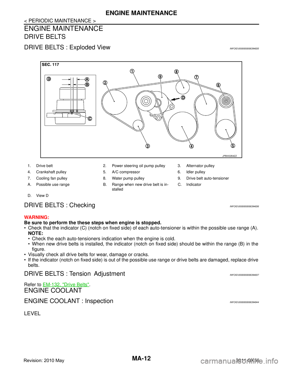
DRIVE BELTS : Exploded ViewINFOID:0000000006394835
DRIVE BELTS : CheckingINFOID:0000000006394836
WARNING:
Be sure to perform the these steps when engine is stopped.
Check that the indicator (C) (notch on fixed side) of each auto-tensioner is within the possible use range (A).
NOTE:
Check the each auto-tensioners indication when the engine is cold.
When new drive belts is installed, the indicator (notch on fixed side) should be within the range (B) in the\
figure.
Visually check all drive belts for wear, damage or cracks.
If the indicator (notch on fixed side) is out of the possible use range or drive belts are damaged, replace drive
belts.
DRIVE BELTS : Tension AdjustmentINFOID:0000000006394837
Refer to EM-132, "Drive Belts".
ENGINE COOLANT
ENGINE COOLANT : InspectionINFOID:0000000006394844
LEVEL
1. Drive belt 2. Power steering oil pump pulley 3. Alternator pulley
4. Crankshaft pulley 5. A/C compressor 6. Idler pulley
7. Cooling fan pulley 8. Water pump pulley 9. Drive belt auto-tensioner
A. Possible use range B. Range when new drive belt is in-
stalledC. Indicator
D. View D
JPBIA3264ZZ
Revision: 2010 May2011 QX56
Page 3691 of 5598
CHASSIS MAINTENANCEMA-21
< PERIODIC MAINTENANCE >
C
DE
F
G H
I
J
K L
M B
MA
N
O A
CHASSIS MAINTENANCE
EXHAUST SYSTEM
EXHAUST SYSTEM : InspectionINFOID:0000000006220926
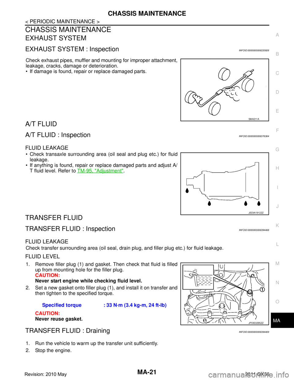
Check exhaust pipes, muffler and mounting for improper attachment,
leakage, cracks, damage or deterioration.
If damage is found, repair or replace damaged parts.
A/T FLUID
A/T FLUID : InspectionINFOID:0000000006376364
FLUID LEAKAGE
Check transaxle surrounding area (oil seal and plug etc.) for fluid
leakage.
If anything is found, repair or replace damaged parts and adjust A/ T fluid level. Refer to TM-95, "
Adjustment".
TRANSFER FLUID
TRANSFER FLUID : InspectionINFOID:0000000006394468
FLUID LEAKAGE
Check transfer surrounding area (oil seal, drain plug, and filler plug etc.) for fluid leakage.
FLUID LEVEL
1. Remove filler plug (1) and gasket. Then check that fluid is filled
up from mounting hole for the filler plug.
CAUTION:
Never start engine whil e checking fluid level.
2. Set a new gasket onto filler plug (1), and install it on transfer and then tighten to the specified torque.
CAUTION:
Never reuse gasket.
TRANSFER FLUID : DrainingINFOID:0000000006394469
1. Run the vehicle to warm up the transfer unit sufficiently.
2. Stop the engine.
SMA211A
JSDIA1912ZZ
Specified torque : 33 N·m (3.4 kg-m, 24 ft-lb)
JPDIE0295ZZ
Revision: 2010 May2011 QX56
Page 3694 of 5598
MA-24
< PERIODIC MAINTENANCE >
CHASSIS MAINTENANCE
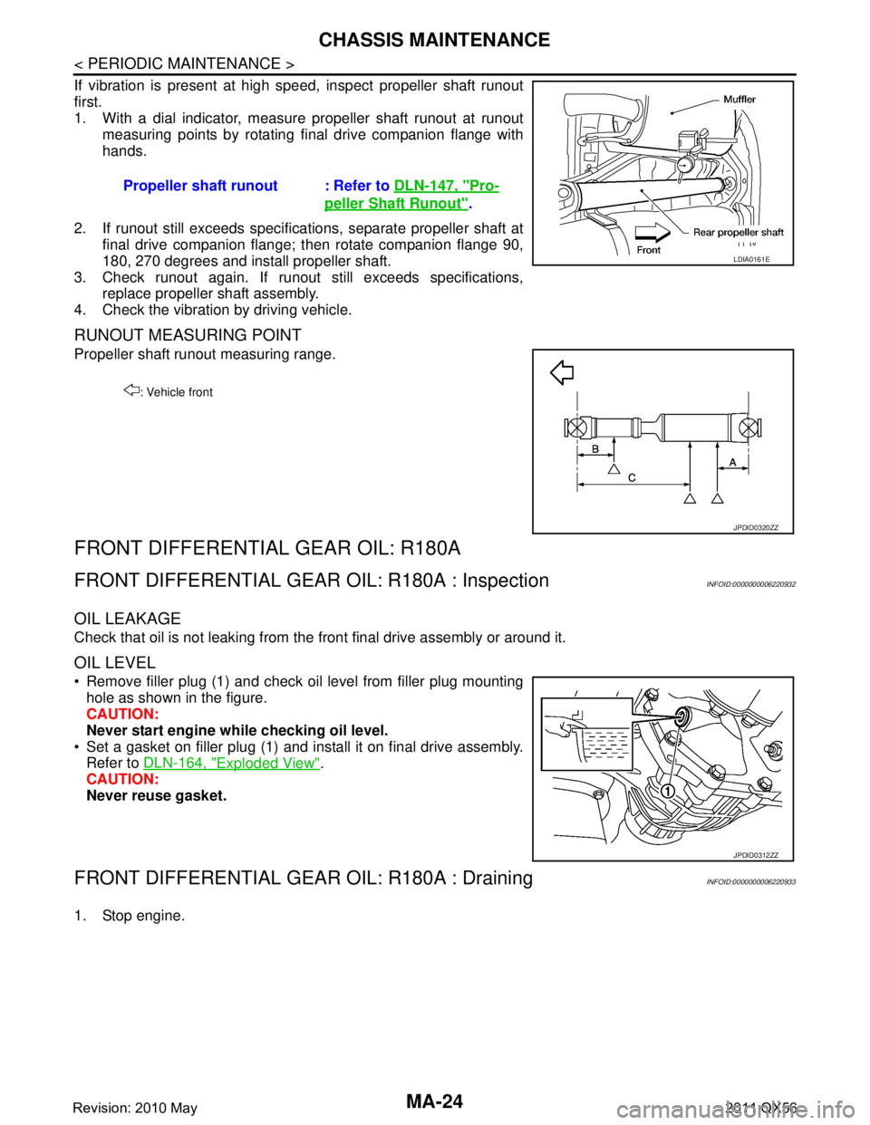
If vibration is present at high speed, inspect propeller shaft runout
first.
1. With a dial indicator, measure propeller shaft runout at runoutmeasuring points by rotating final drive companion flange with
hands.
2. If runout still exceeds specifications, separate propeller shaft at final drive companion flange; then rotate companion flange 90,
180, 270 degrees and install propeller shaft.
3. Check runout again. If runout still exceeds specifications, replace propeller shaft assembly.
4. Check the vibration by driving vehicle.
RUNOUT MEASURING POINT
Propeller shaft runout measuring range.
FRONT DIFFERENTIAL GEAR OIL: R180A
FRONT DIFFERENTIAL GEAR OIL: R180A : InspectionINFOID:0000000006220932
OIL LEAKAGE
Check that oil is not leaking from the front final drive assembly or around it.
OIL LEVEL
Remove filler plug (1) and check oil level from filler plug mounting
hole as shown in the figure.
CAUTION:
Never start engine while checking oil level.
Set a gasket on filler plug (1) and install it on final drive assembly. Refer to DLN-164, "
Exploded View".
CAUTION:
Never reuse gasket.
FRONT DIFFERENTIAL GEAR OIL: R180A : DrainingINFOID:0000000006220933
1. Stop engine.Propeller shaft runout : Refer to
DLN-147, "
Pro-
peller Shaft Runout".
LDIA0161E
: Vehicle front
JPDID0320ZZ
JPDID0312ZZ
Revision: 2010 May2011 QX56