2011 INFINITI QX56 checking oil
[x] Cancel search: checking oilPage 2582 of 5598
EM-20
< PERIODIC MAINTENANCE >
DRIVE BELTS
PERIODIC MAINTENANCE
DRIVE BELTS
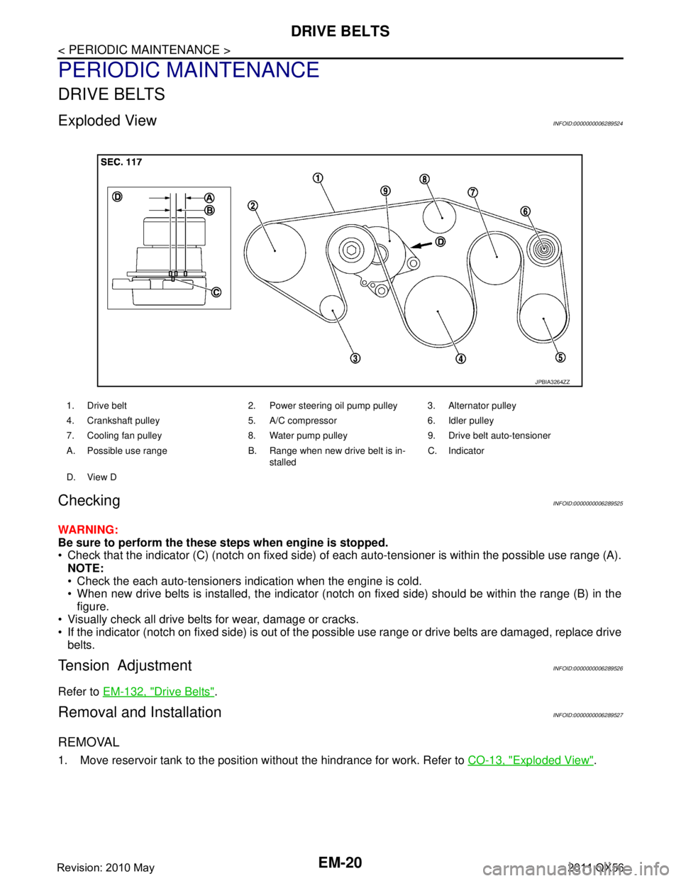
Exploded ViewINFOID:0000000006289524
CheckingINFOID:0000000006289525
WARNING:
Be sure to perform the these steps when engine is stopped.
Check that the indicator (C) (notch on fixed side) of each auto-tensioner is within the possible use range (A).
NOTE:
Check the each auto-tensioners indication when the engine is cold.
When new drive belts is installed, the indicator (notch on fixed side) should be within the range (B) in the\
figure.
Visually check all drive belts for wear, damage or cracks.
If the indicator (notch on fixed side) is out of the possible use range or drive belts are damaged, replace drive
belts.
Tension AdjustmentINFOID:0000000006289526
Refer to EM-132, "Drive Belts".
Removal and InstallationINFOID:0000000006289527
REMOVAL
1. Move reservoir tank to the position without the hindrance for work. Refer to CO-13, "Exploded View".
1. Drive belt 2. Power steering oil pump pulley 3. Alternator pulley
4. Crankshaft pulley 5. A/C compressor 6. Idler pulley
7. Cooling fan pulley 8. Water pump pulley 9. Drive belt auto-tensioner
A. Possible use range B. Range when new drive belt is in-
stalledC. Indicator
D. View D
JPBIA3264ZZ
Revision: 2010 May2011 QX56
Page 2615 of 5598
FUEL INJECTOR AND FUEL TUBEEM-53
< REMOVAL AND INSTALLATION >
C
DE
F
G H
I
J
K L
M A
EM
NP
O
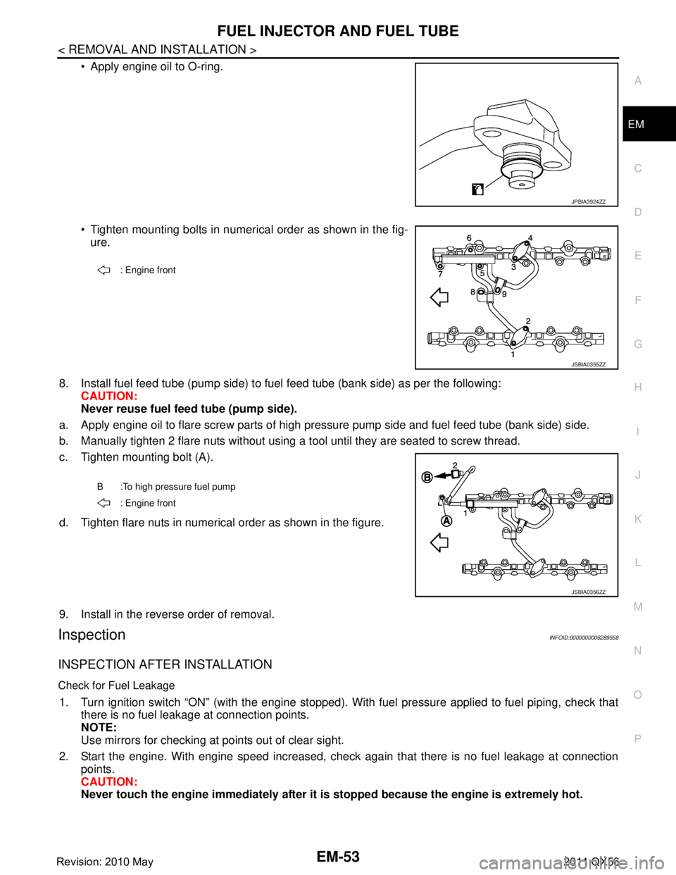
Apply engine oil to O-ring.
Tighten mounting bolts in numerical order as shown in the fig-
ure.
8. Install fuel feed tube (pump side) to fuel feed tube (bank side) as per the following:
CAUTION:
Never reuse fuel feed tube (pump side).
a. Apply engine oil to flare screw parts of high pr essure pump side and fuel feed tube (bank side) side.
b. Manually tighten 2 flare nuts without using a t ool until they are seated to screw thread.
c. Tighten mounting bolt (A).
d. Tighten flare nuts in numerical order as shown in the figure.
9. Install in the reverse order of removal.
InspectionINFOID:0000000006289558
INSPECTION AFTER INSTALLATION
Check for Fuel Leakage
1. Turn ignition switch “ON” (with the engine stopped). With fuel pressure applied to fuel piping, check that
there is no fuel leakage at connection points.
NOTE:
Use mirrors for checking at points out of clear sight.
2. Start the engine. With engine speed increased, check again that there is no fuel leakage at connection
points.
CAUTION:
Never touch the engine immediately after it is stopped because the engine is extremely hot.
JPBIA3924ZZ
: Engine front
JSBIA0355ZZ
B :To high pressure fuel pump
: Engine front
JSBIA0356ZZ
Revision: 2010 May2011 QX56
Page 2646 of 5598
EM-84
< REMOVAL AND INSTALLATION >
CAMSHAFT
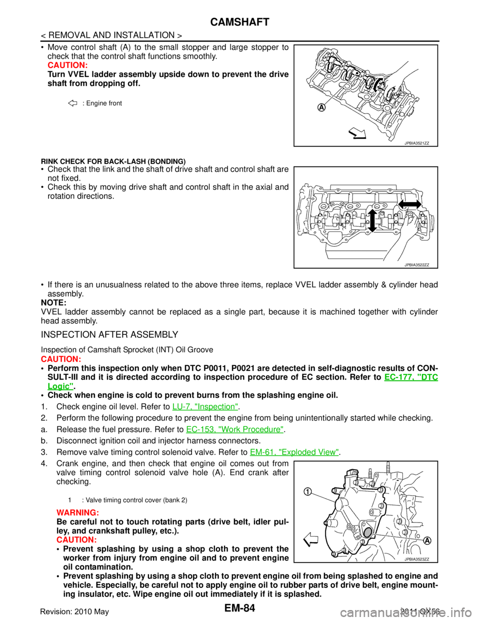
Move control shaft (A) to the small stopper and large stopper tocheck that the control shaft functions smoothly.
CAUTION:
Turn VVEL ladder assembly upside down to prevent the drive
shaft from dropping off.
RINK CHECK FOR BACK-LASH (BONDING) Check that the link and the shaft of drive shaft and control shaft are
not fixed.
Check this by moving drive shaft and control shaft in the axial and
rotation directions.
If there is an unusualness related to the above three items, replace VVEL ladder assembly & cylinder head
assembly.
NOTE:
VVEL ladder assembly cannot be replaced as a singl e part, because it is machined together with cylinder
head assembly.
INSPECTION AFTER ASSEMBLY
Inspection of Camshaft Sprocket (INT) Oil Groove
CAUTION:
Perform this inspection only when DTC P0011, P 0021 are detected in self-diagnostic results of CON-
SULT-III and it is directed according to inspection procedure of EC section. Refer to EC-177, "
DTC
Logic".
Check when engine is cold to prevent burns from the splashing engine oil.
1. Check engine oil level. Refer to LU-7, "
Inspection".
2. Perform the following procedure to prevent the engine from being unintentionally started while checking.
a. Release the fuel pressure. Refer to EC-153, "
Work Procedure".
b. Disconnect ignition coil and injector harness connectors.
3. Remove valve timing control solenoid valve. Refer to EM-61, "
Exploded View".
4. Crank engine, and then check that engine oil comes out from valve timing control solenoid valve hole (A). End crank after
checking.
WARNING:
Be careful not to touch rotati ng parts (drive belt, idler pul-
ley, and crankshaft pulley, etc.).
CAUTION:
Prevent splashing by using a shop cloth to prevent the worker from injury from en gine oil and to prevent engine
oil contamination.
Prevent splashing by using a shop cloth to prevent engine oil from being splashed to engine and
vehicle. Especially, be careful not to apply engine oil to rubber parts of drive belt, engine mount-
ing insulator, etc. Wipe engine oil out immediately if it is splashed.
: Engine front
JPBIA3521ZZ
JPBIA3522ZZ
1 : Valve timing control cover (bank 2)
JPBIA3523ZZ
Revision: 2010 May2011 QX56
Page 2656 of 5598

EM-94
< REMOVAL AND INSTALLATION >
CYLINDER HEAD
Check if the contact area band is continuous all around the circum-ference.
- If not, grind to adjust valve fitting and check again. If the contacting surface still has “NG” conditions even after the re-check, replace
valve seat (EXH). Refer to EM-86, "
Exploded View". (Exhaust
side)
- If not, replace VVEL ladder assembly & cylinder head assembly. Refer to EM-86, "
Exploded View". (Intake side)
NOTE:
Since the valve seat (INT) cannot be replaced by t he piece, VVEL ladder assembly & cylinder head assem-
bly replacement are required.
Valve Spring (with valve spring seat) Squareness
Set a try square (A) along the side of valve spring (with valve
spring seat) and rotate spring. Measure the maximum clearance
between the top of spring and try square.
If it exceeds the limit.
- Replace valve spring (with valve spring seat) (EXH). Refer to EM-
86, "Exploded View". (Exhaust side)
- Replace VVEL ladder assembly & cylinder head assembly. Refer
to EM-86, "
Exploded View". (Intake side)
NOTE:
Since the valve spring (with valve spring seat) (INT) c annot be replaced by the piece, VVEL ladder assembly
& cylinder head assembly replacement are required.
Valve Spring Dimensions and Valve Spring Pressure Load
Check the valve spring (with valve spring seat) pressure at speci- fied spring height.
If the installation load or load with valve open is out of the stan- dard.
- Replace valve spring (with valve spring seat) (EXH). Refer to EM-
86, "Exploded View". (Exhaust side)
- Replace VVEL ladder assembly & cylinder head assembly. Refer to EM-86, "
Exploded View". (Intake side)
NOTE:
Since the valve spring (with valve spring seat) (INT) c annot be replaced by the piece, VVEL ladder assembly
& cylinder head assembly replacement are required.
INSPECTION AFTER ASSEMBLY
Inspection for Leakage
The following are procedures for checking fluid leakage, lubricant leakage.
Before starting engine, check oil/fluid levels includi ng engine coolant and engine oil. If any are less than the
required quantity, fill them to the specified level. Refer to MA-10, "
Fluids and Lubricants".
Follow the procedure below to check for fuel leakage.
- Turn ignition switch to the “ON” position (with engi ne stopped). With fuel pressure applied to fuel piping,
check for fuel leakage at connection points.
- Start engine. With engine speed increased, che ck again for fuel leakage at connection points.
Run engine to check for unusual noise and vibration. NOTE:
A: OK
B: NG
JPBIA0187ZZ
B : Contact
Limit : Refer to EM-135, "CylinderHead".
JPBIA0189ZZ
Standard
: Refer to EM-135, "
CylinderHead".
SEM113
Revision: 2010 May2011 QX56
Page 2664 of 5598
EM-102
< UNIT REMOVAL AND INSTALLATION >
ENGINE ASSEMBLY
INSTALLATION
Install in the reverse order of removal.
CAUTION:
When replacing an engine or transmission you must make sure the dowels are installed correctly
during re-assembly.Improper alignment caused by mi ssing dowels may cause vibration, oil leaks or
breakage of drivetrain components.
InspectionINFOID:0000000006289578
INSPECTION AFTER INSTALLATION
Inspection for Leakage
The following are procedures for checking fluid leakage, lubricant leakage. Before starting engine, check oil/fluid levels includi ng engine coolant and engine oil. If any are less than the
required quantity, fill them to the specified level. Refer to MA-10, "
Fluids and Lubricants".
Follow the procedure below to check for fuel leakage.
- Turn ignition switch to the “ON” position (with engi ne stopped). With fuel pressure applied to fuel piping,
check for fuel leakage at connection points.
- Start engine. With engine speed increased, che ck again for fuel leakage at connection points.
Run engine to check for unusual noise and vibration. NOTE:
If hydraulic pressure inside chain tensioner drops af ter removal/installation, slack in guide may generate a
pounding noise during and just after the engine start. However, this does not indicate a malfunction. The
noise will stop after hydraulic pressure rises.
Warm up engine thoroughly to check that there is no leak age of fuel, or any oil/fluids including engine oil and
engine coolant.
Bleed air from lines and hoses of applic able lines, such as in cooling system.
After cooling down engine, again check oil/fluid levels including engine oil and engine coolant. Refill them to
the specified level, if necessary.
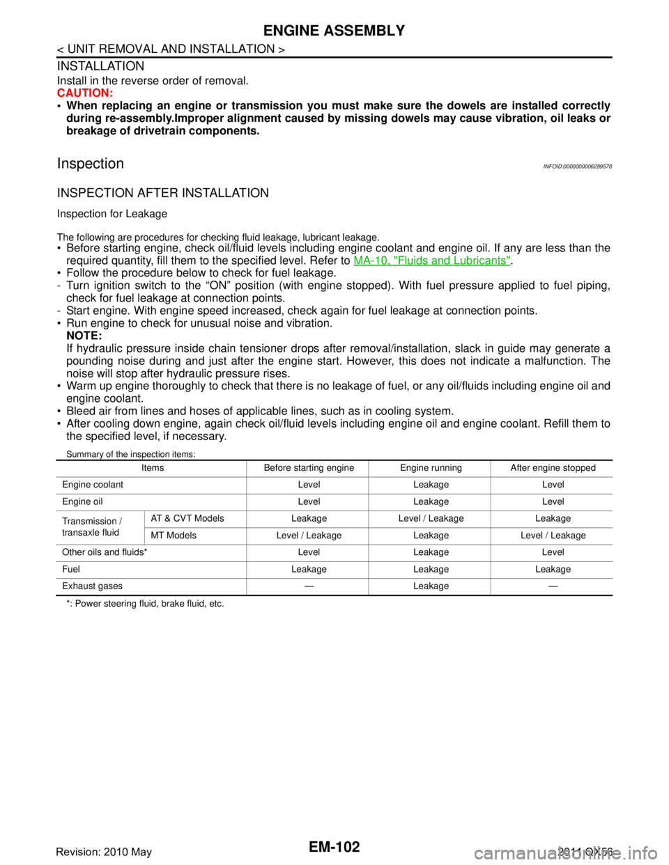
Summary of the inspection items:
*: Power steering fluid, brake fluid, etc. Items Before starting engine Engine running After engine stopped
Engine coolant Level Leakage Level
Engine oil Level Leakage Level
Transmission /
transaxle fluid AT & CVT Models Leakage Level / Leakage Leakage
MT Models Level / Leakage Leakage Level / Leakage
Other oils and fluids* Level Leakage Level
Fuel Leakage Leakage Leakage
Exhaust gases — Leakage —
Revision: 2010 May2011 QX56
Page 2965 of 5598
GI-1
GENERAL INFORMATION
C
DE
F
G H
I
J
K L
M B
GI
SECTION GI
N
O P
CONTENTS
GENERAL INFORMATION
HOW TO USE THIS MANU AL ......................3
HOW TO USE THIS MANUAL ....................... .....3
Description .......................................................... ......3
Terms ........................................................................3
Units ..........................................................................3
Contents ....................................................................3
Relation between Illustrations and Descriptions .......4
Components ..............................................................4
HOW TO FOLLOW TROUBLE DIAGNOSES .....6
Description ................................................................6
How to Follow Test Groups in Trouble Diagnosis ......6
Key to Symbols Signifying Measurements or Pro-
cedures ............................................................... ......
7
HOW TO READ WIRING DIAGRAMS ................9
Connector Symbols ............................................. ......9
Sample/Wiring Diagram -Example- .........................10
Connector Information .............................................12
ABBREVIATIONS .......................................... ....14
Abbreviation List .................................................. ....14
TIGHTENING TORQUE OF STANDARD
BOLTS ................................................................
19
Description .......................................................... ....19
Tightening Torque Table (New Standard Includ-
ed) ...........................................................................
19
RECOMMENDED CHEMICAL PRODUCTS
AND SEALANTS ................................................
22
Recommended Chemical Products and Sealants ....22
VEHICLE INFORMATION ............................23
IDENTIFICATION INFORMATION ................. ....23
Model Variation ................................................... ....23
Information About Identification or Model Code ......23
Dimensions .............................................................25
Wheels & Tires ........................................................25
PRECAUTION ..............................................26
PRECAUTIONS .................................................26
Description ........................................................... ....26
Precaution for Supplemental Restraint System
(SRS) "AIR BAG" and "SEAT BELT PRE-TEN-
SIONER" .................................................................
26
Precautions For Xenon Headlamp Service .............26
Precaution Necessary for Steering Wheel Rota-
tion after Battery Disconnect ...................................
27
Precaution for Procedure without Cowl Top Cover ....27
General Precautions ................................................27
Three Way Catalyst .................................................29
Multiport Fuel Injection System or Engine Control
System .....................................................................
29
Hoses ......................................................................29
Engine Oils ..............................................................30
Air Conditioning .......................................................31
Fuel ..........................................................................31
LIFTING POINT .................................................32
Pantograph Jack ......................................................32
Garage Jack and Safety Stand ................................32
2-Pole Lift ................................................................33
TOW TRUCK TOWING .....................................34
Tow Truck Towing ...................................................34
Vehicle Recovery (Freeing a Stuck Vehicle) ...........34
BASIC INSPECTION ...................................36
SERVICE INFORMATION FOR ELECTRICAL
INCIDENT ..........................................................
36
Work Flow ............................................................ ....36
Control Units and Electrical Parts ............................36
How to Check Terminal ...........................................37
Intermittent Incident .................................................40
Circuit Inspection .....................................................43
CONSULT-III/GST CHECKING SYSTEM .........48
Description ...............................................................48
CONSULT-III Function and System Application*1 ....48
Revision: 2010 May2011 QX56
Page 3001 of 5598
SERVICE INFORMATION FOR ELECTRICAL INCIDENTGI-37
< BASIC INSPECTION >
C
DE
F
G H
I
J
K L
M B
GI
N
O P
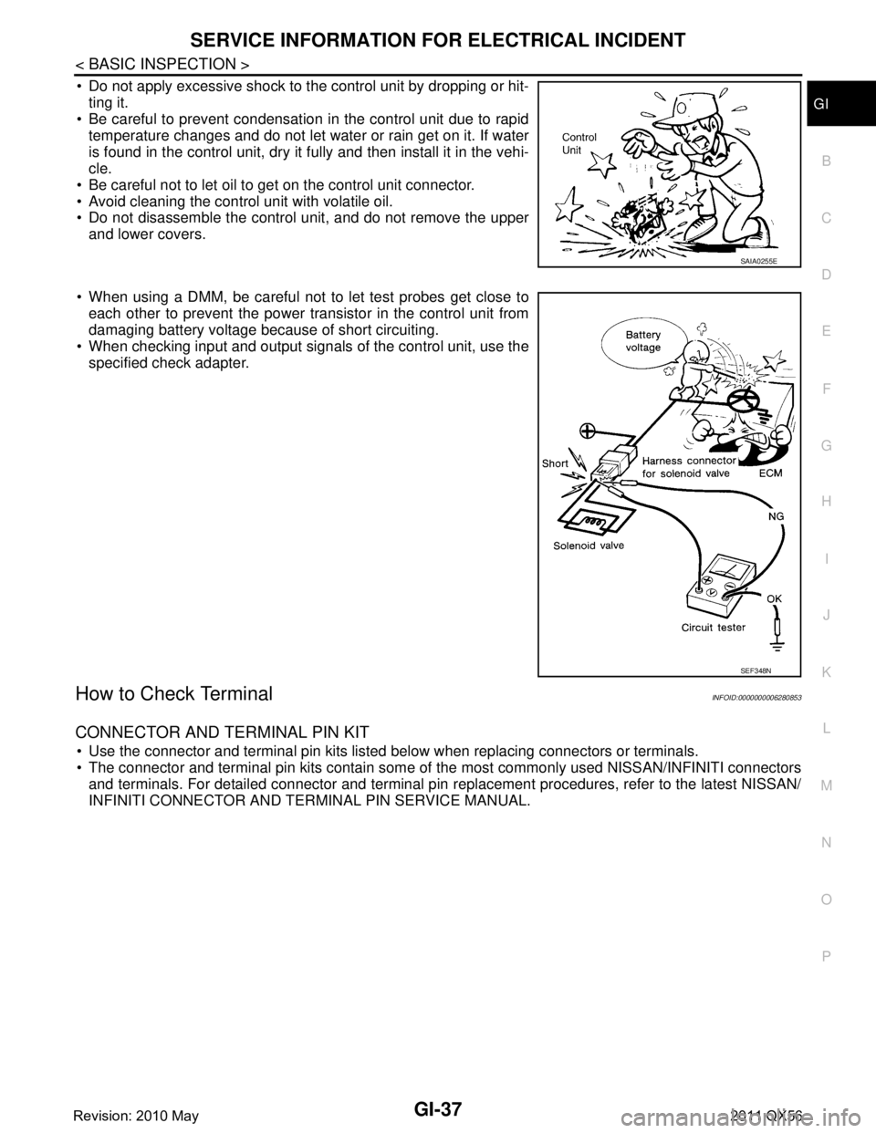
Do not apply excessive shock to the control unit by dropping or hit- ting it.
Be careful to prevent condensation in the control unit due to rapid
temperature changes and do not let water or rain get on it. If water
is found in the control unit, dry it fully and then install it in the vehi-
cle.
Be careful not to let oil to get on the control unit connector.
Avoid cleaning the control unit with volatile oil.
Do not disassemble the contro l unit, and do not remove the upper
and lower covers.
When using a DMM, be careful not to let test probes get close to each other to prevent the power transistor in the control unit from
damaging battery voltage because of short circuiting.
When checking input and output signals of the control unit, use the
specified check adapter.
How to Check TerminalINFOID:0000000006280853
CONNECTOR AND TERMINAL PIN KIT
Use the connector and terminal pin kits listed below when replacing connectors or terminals.
The connector and terminal pin kits contain some of the most commonly used NISSAN/INFINITI connectors
and terminals. For detailed connector and terminal pin r eplacement procedures, refer to the latest NISSAN/
INFINITI CONNECTOR AND TERMINAL PIN SERVICE MANUAL.
SAIA0255E
SEF348N
Revision: 2010 May2011 QX56
Page 3066 of 5598
HA-10
< PREPARATION >
PREPARATION
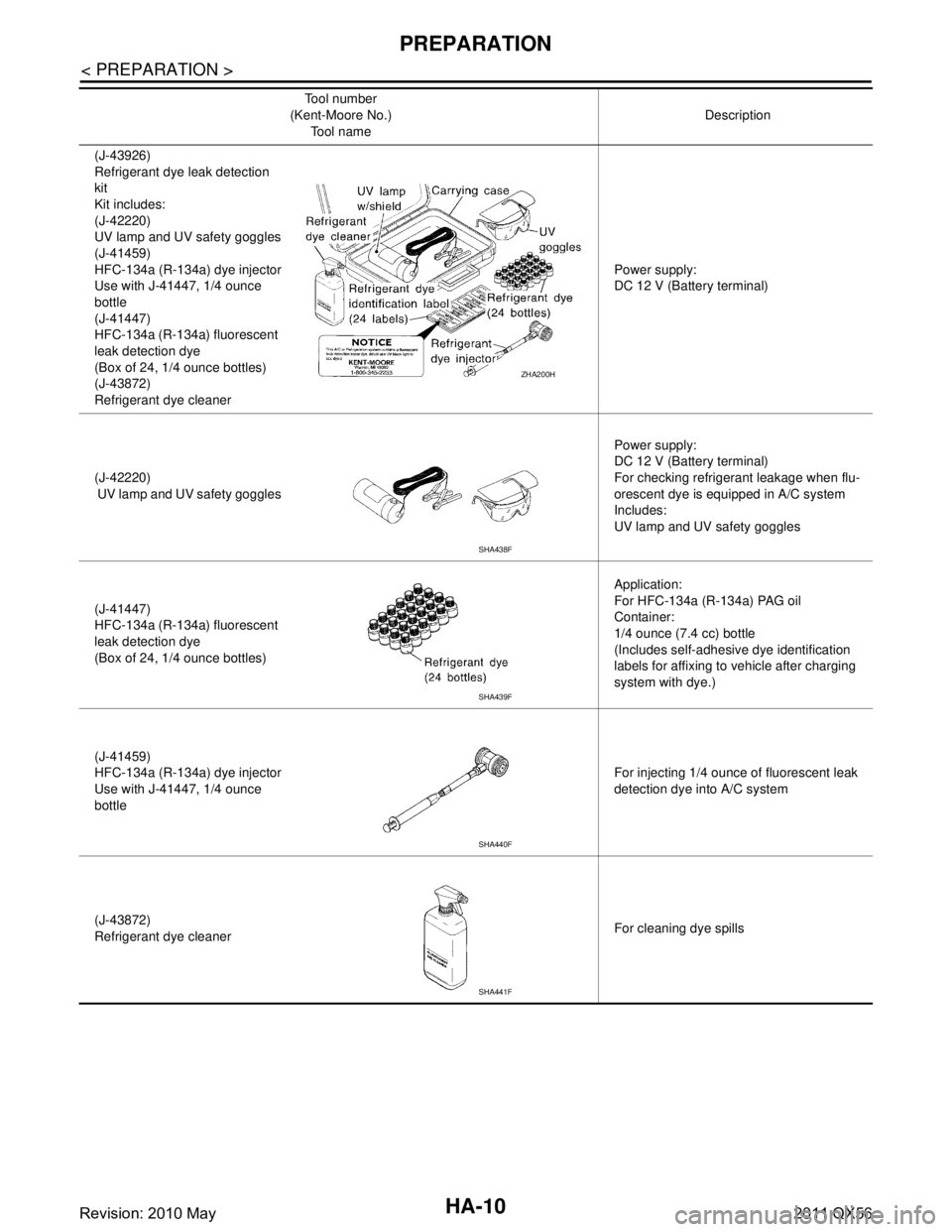
(J-43926)
Refrigerant dye leak detection
kit
Kit includes:
(J-42220)
UV lamp and UV safety goggles
(J-41459)
HFC-134a (R-134a) dye injector
Use with J-41447, 1/4 ounce
bottle
(J-41447)
HFC-134a (R-134a) fluorescent
leak detection dye
(Box of 24, 1/4 ounce bottles)
(J-43872)
Refrigerant dye cleanerPower supply:
DC 12 V (Battery terminal)
(J-42220)
UV lamp and UV safety goggles Power supply:
DC 12 V (Battery terminal)
For checking refrigerant leakage when flu-
orescent dye is equipped in A/C system
Includes:
UV lamp and UV safety goggles
(J-41447)
HFC-134a (R-134a) fluorescent
leak detection dye
(Box of 24, 1/4 ounce bottles) Application:
For HFC-134a (R-134a) PAG oil
Container:
1/4 ounce (7.4 cc) bottle
(Includes self-adhesive dye identification
labels for affixing to vehicle after charging
system with dye.)
(J-41459)
HFC-134a (R-134a) dye injector
Use with J-41447, 1/4 ounce
bottle For injecting 1/4 ounce of fluorescent leak
detection dye into A/C system
(J-43872)
Refrigerant dye cleaner For cleaning dye spills
Tool number
(Kent-Moore No.)
Tool name Description
ZHA200H
SHA438F
SHA439F
SHA440F
SHA441F
Revision: 2010 May2011 QX56