2011 INFINITI QX56 check oil
[x] Cancel search: check oilPage 1770 of 5598
DLK-234
< REMOVAL AND INSTALLATION >
BACK DOOR
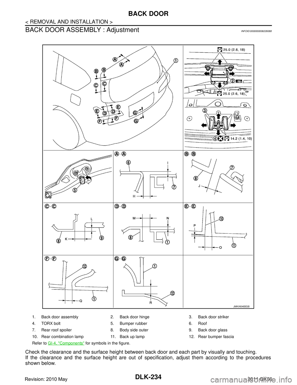
BACK DOOR ASSEMBLY : Adjustment
INFOID:0000000006226088
Check the clearance and the surface height between back door and each part by visually and touching.
If the clearance and the surface height are out of spec ification, adjust them according to the procedures
shown below.
1. Back door assembly 2. Back door hinge 3. Back door striker
4. TORX bolt 5. Bumper rubber 6. Roof
7. Rear roof spoiler 8. Body side outer 9. Back door glass
10. Rear combination lamp 11. Back up lamp 12. Rear bumper fascia
Refer to GI-4, "
Components" for symbols in the figure.
JMKIA5483GB
Revision: 2010 May2011 QX56
Page 1771 of 5598
BACK DOORDLK-235
< REMOVAL AND INSTALLATION >
C
DE
F
G H
I
J
L
M A
B
DLK
N
O P
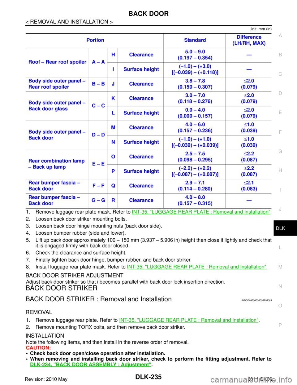
Unit: mm (in)
1. Remove luggage rear plate mask. Refer to INT-35, "LUGGAGE REAR PLATE : Removal and Installation".
2. Loosen back door striker mounting bolts.
3. Loosen back door hinge mounting nuts (back door side).
4. Loosen bumper rubber (side and lower).
5. Lift up back door approximately 100 – 150 mm (3.937 – 5.906 in) height then close it lightly and check that
it is engaged firmly with back door closed.
6. Check the clearance and surface height.
7. Finally tighten back door hinge, bumper rubber, and back door striker.
8. Install luggage rear plate mask. Refer to INT-35, "
LUGGAGE REAR PLATE : Removal and Installation".
BACK DOOR STRIKER ADJUSTMENT
Adjust back door striker so that i becomes parallel with back door lock insertion direction.
BACK DOOR STRIKER
BACK DOOR STRIKER : Removal and InstallationINFOID:0000000006226089
REMOVAL
1. Remove luggage rear plate. Refer to INT-35, "LUGGAGE REAR PLATE : Removal and Installation".
2. Remove mounting TORX bolts, and then remove back door striker.
INSTALLATION
Note the following items, and then install in the reverse order of removal.
CAUTION:
Check back door open/close ope ration after installation.
When removing and installing b ack door striker, check to perform th e fitting adjustment. Refer to
DLK-234, "
BACK DOOR ASSEMBLY : Adjustment".
Portion Standard
Difference
(LH/RH, MAX)
Roof – Rear roof spoiler A – A H Clearance
5.0 – 9.0
(0.197 – 0.354) —
I Surface height (
− 1.0) – (+3.0)
[( −0.039) – (+0.118)] —
Body side outer panel –
Rear roof spoiler B – B J Clearance 3.8 – 7.8
(0.150 – 0.307) ≤
2.0
(0.079)
Body side outer panel –
Back door glass C – CK Clearance
3.0 – 7.0
(0.118 – 0.276) ≤
2.0
(0.079)
L Surface height 0.0 – 4.0
(0.000 – 0.157) ≤
2.0
(0.079)
Body side outer panel –
Back door D – DM Clearance
4.0 – 6.0
(0.157 – 0.236) ≤
1.0
(0.039)
N Surface height (
− 1.0) – (+1.0)
[( −0.039) – (+0.039)] ≤
1.0
(0.039)
Rear combination lamp
– Back up lamp E – EO Clearance
2.5 – 7.5
(0.098 – 0.295) ≤
2.2
(0.087)
P Surface height (
− 2.2) – (+2.2)
[( −0.087) – (+0.087)] ≤
2.2
(0.087)
Rear bumper fascia –
Back door F – F Q Clearance 2.9 – 7.1
(0.114 – 0.280) ≤
2.1
(0.083)
Rear bumper fascia –
Back door G – G R Clearance 4.0 – 8.0
(0.157 – 0.315) —
Revision: 2010 May2011 QX56
Page 1773 of 5598
BACK DOORDLK-237
< REMOVAL AND INSTALLATION >
C
DE
F
G H
I
J
L
M A
B
DLK
N
O P
BACK DOOR STAY : Disposal INFOID:0000000006226092
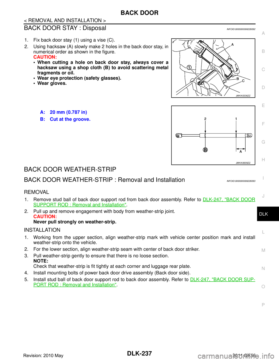
1. Fix back door stay (1) using a vise (C).
2. Using hacksaw (A) slowly make 2 holes in the back door stay, in numerical order as shown in the figure.
CAUTION:
When cutting a hole on back door stay, always cover ahacksaw using a shop cloth (B) to avoid scattering metal
fragments or oil.
Wear eye protection (safety glasses).
Wear gloves.
BACK DOOR WEATHER-STRIP
BACK DOOR WEATHER-STRIP : Removal and InstallationINFOID:0000000006226093
REMOVAL
1. Remove stud ball of back door support rod from back door assembly. Refer to DLK-247, "BACK DOOR
SUPPORT ROD : Removal and Installation".
2. Pull up and remove engagement with body from weather-strip joint. CAUTION:
Never pull strongly on weather-strip.
INSTALLATION
1. Working from the upper section, align weather-strip mark with vehicle center position mark and install
weather-strip onto the vehicle.
2. For the lower section, align weather-str ip seam with center of back door striker.
3. Pull weather-strip gently to ensure that there is no loose section. NOTE:
Check that weather-strip is fit tightly at each corner and luggage rear plate.
4. Install mounting bolts of power back door drive assembly (Back door side).
5. Install stud ball of back door support rod to back door assembly. Refer to DLK-247, "
BACK DOOR SUP-
PORT ROD : Removal and Installation".
JMKIA3336ZZ
A: 20 mm (0.787 in)
B: Cut at the groove.
JMKIA3609ZZ
Revision: 2010 May2011 QX56
Page 1789 of 5598
CAB MOUNTING INSULATORDLK-253
< REMOVAL AND INSTALLATION >
C
DE
F
G H
I
J
L
M A
B
DLK
N
O P
Remove brake tube from connector (front wheel well LH and RH side). Refer to BR-22, "FRONT :
Exploded View"
Vehicle center side
Remove A/T control cable from manual lever. Refer to TM-178, "
Removal and Installation".
Separate parking brake rear cable (LH and RH) from parking brake front cable. Refer to PB-5, "
Removal
and Installation".
Remove engine room harness connector (frame assembly RH center side). Refer to PG-146, "
Engine
Room Harness"
- Remove harness connector protector.
- Disconnect chassis harness connector from engine room harness connector.
- Remove harness bracket bolt, and then remove engi ne room harness connector from frame assembly.
Vehicle rear side
Remove EVAP hose (canister side).
Remove rear final drive breather hose from air breather tube (body side). Refer to DLN-201, "
Removal
and Installation".
Disconnect body harness connector from chassis harness connectors (frame assembly LH rear side).
Refer to PG-150, "
Body Harness"
6. Set safety stand to frame assembly. Release arm of 2-pole lift.
7. Remove cab mounting insulator bolts.
8. Set arm of 2-pole lift to body side sill portion of body.
9. Slowly lift 2-pole lift.
CAUTION:
Check that there is no inte rference with the vehicle.
Check that all connection points are disconnected.
10. Remove cab mounting insulator.
INSTALLATION
Note the following items, and then install in the reverse order of removal.
CAUTION:
Before starting engine, check oil/fl uid levels including engine coolant and engine oil. If levels are
less than the required quantity, fill to the specified level. Refer to MA-10, "
Fluids and Lubricants".
Warm up engine thoroughly to check that there is no leakage of fuel, exhaust gases, or any oil/fluids
including engine oil and engine coolant.
Revision: 2010 May2011 QX56
Page 1805 of 5598
DLN-3
CEF
G H
I
J
K L
M A
B
DLN
N
O P
U1000 CAN COMM CIRCUIT ......................... ....91
Description .......................................................... ....91
DTC Logic ...............................................................91
Diagnosis Procedure ...............................................91
U1010 CONTROL UNIT (CAN) ..........................92
Description .......................................................... ....92
DTC Logic ...............................................................92
Diagnosis Procedure ...............................................92
POWER SUPPLY AND GROUND CIRCUIT ......93
Description .......................................................... ....93
Diagnosis Procedure ...............................................93
4WD WARNING LAMP ......................................97
Component Function Check ................................ ....97
Diagnosis Procedure ...............................................97
4WD INDICATOR LAMP ....................................98
Component Function Check ................................ ....98
Diagnosis Procedure ...............................................98
SYMPTOM DIAGNOSIS ..............................99
HEAVY TIGHT-CORNER BRAKING SYMP-
TOM OCCURS . .............................................. ....
99
Description .......................................................... ....99
Diagnosis Procedure ...............................................99
4WD MODE DOES NOT CHANGE ..................100
Description .......................................................... ..100
Diagnosis Procedure .............................................100
4WD MODE INDICATOR LAMP CONTINUES
BLINKING .........................................................
101
Description .......................................................... ..101
Diagnosis Procedure .............................................101
4WD WARNING LAMP BLINKS QUICKLY .....102
Description .......................................................... ..102
4WD WARNING LAMP BLINKS SLOWLY .....103
Description .......................................................... ..103
Diagnosis Procedure .............................................103
INFORMATION DISPLAY IS NOT DIS-
PLAYED ...........................................................
104
Description .......................................................... ..104
Diagnosis Procedure .............................................104
NOISE, VIBRATION AND HARSHNESS
(NVH) TROUBLESHOOTING ..........................
105
NVH Troubleshooting Chart ................................ ..105
PERIODIC MAINTENANCE .......................106
TRANSFER FLUID ......................................... ..106
Inspection ............................................................ ..106
Draining .................................................................106
Refilling .................................................................106
REMOVAL AND INSTALLATION .............107
TRANSFER CONTROL UNIT .........................107
Removal and Installation ..................................... ..107
4WD MODE SWITCH ......................................108
Removal and Installation .......................................108
FRONT OIL SEAL ...........................................109
Exploded View .......................................................109
Removal and Installation .......................................109
REAR OIL SEAL .............................................111
Exploded View .......................................................111
Removal and Installation .......................................111
Adjustment .............................................................112
TRANSFER CONTROL ACTUATOR .............114
Exploded View .......................................................114
Removal and Installation .......................................114
Inspection ..............................................................114
TRANSFER HI-LO POSITION SENSOR ........116
Exploded View .......................................................116
Removal and Installation .......................................116
Inspection ..............................................................116
TRANSFER ROTARY POSITION SENSOR ...117
Exploded View .......................................................117
Removal and Installation .......................................117
Inspection ..............................................................118
TRANSFER LOCK POSITION SENSOR ........119
Exploded View .......................................................119
Removal and Installation .......................................119
Inspection ..............................................................119
TRANSFER FLUID TEMPERATURE SEN-
SOR .................................................................
120
Exploded View .......................................................120
Removal and Installation .......................................120
Inspection ..............................................................120
UNIT REMOVAL AND INSTALLATION ....121
TRANSFER ASSEMBLY ................................121
Exploded View ..................................................... ..121
Removal and Installation .......................................121
INPUT OIL SEAL ............................................123
Exploded View .......................................................123
Removal and Installation .......................................123
SERVICE DATA AND SPECIFICATIONS
(SDS) ............... ...........................................
124
SERVICE DATA AND SPECIFICATIONS
(SDS) ...............................................................
124
General Specifications ......................................... ..124
FRONT PROPELLER SHAFT: 2F P15
PREPARATION ........ .................................
125
PREPARATION ...............................................125
Revision: 2010 May2011 QX56
Page 1844 of 5598
![INFINITI QX56 2011 Factory Service Manual
DLN-42
< BASIC INSPECTION >[TRANSFER: ATX90A]
ADDITIONAL SERVICE WHEN
REPLACING TRANSFER ASSEMBLY
ADDITIONAL SERVICE WHEN REPLACING TRANSFER ASSEMBLY
DescriptionINFOID:0000000006222236
Perform writi INFINITI QX56 2011 Factory Service Manual
DLN-42
< BASIC INSPECTION >[TRANSFER: ATX90A]
ADDITIONAL SERVICE WHEN
REPLACING TRANSFER ASSEMBLY
ADDITIONAL SERVICE WHEN REPLACING TRANSFER ASSEMBLY
DescriptionINFOID:0000000006222236
Perform writi](/manual-img/42/57033/w960_57033-1843.png)
DLN-42
< BASIC INSPECTION >[TRANSFER: ATX90A]
ADDITIONAL SERVICE WHEN
REPLACING TRANSFER ASSEMBLY
ADDITIONAL SERVICE WHEN REPLACING TRANSFER ASSEMBLY
DescriptionINFOID:0000000006222236
Perform writing unit parameter, transfer fluid viscosity learning and initial calibration after replacing transfer
assembly. Refer to DLN-42, "
Work Procedure".
Work ProcedureINFOID:0000000006222237
NOTE:
In fail-safe mode, can not perform work s upport. (Except that DTC P181F is detected.)
1.WRITE UNIT PARAMETER
Perform writing unit parameter to control unit. Refer to DLN-48, "
Work Procedure".
>> GO TO 2.
2.PREPARATION BEFORE WORK
With CONSULT-III
1. Start the engine. CAUTION:
Never drive the vehicle.
2. Check “4WD MODE”, “T/M RANGE”, “COMER V HCL SPEED”, “MOTOR POWER SUP” of CONSULT-III
“DATA MONITOR” for “ALL MODE AWD/4WD”.
3. Continue the following condition more than 10 seconds.
>> GO TO 3.
3.PERFORM TRANSFER FLUID VISCOSITY LEARNING
With CONSULT-III
1. Select “OIL DETERIORATION INFO RESET” of CONSULT-III “WORK SUPPORT” for “ALL MODE AWD/
4WD”.
2. Select “Start”.
>> GO TO 4.
4.INITIAL CALIBRATION
With CONSULT-III
1. Select “START CALIBRATION” of CONSULT- III “WORK SUPPORT” for “ALL MODE AWD/4WD”.
2. Wait until the motor operation stop. (After approximately 10 seconds)
>> GO TO 5.
5.PERFORM SELF-DIAGNOSIS
With CONSULT-III
1. Erase self-diagnosis result for “ALL MODE AWD/4WD”.
2. Turn the ignition switch ON to OFF. CAUTION:
Wait for 10 seconds after turn ing ignition switch OFF.
3. Start the engine. CAUTION:
Never drive the vehicle.
4. Perform self-diagnosis for “ALL MODE AWD/4WD”.
4WD MODE : AUTO
T/M RANGE : N
COMPER VHCL SPEED : 0 km/h (Never drive the vehicle)
MOTOR POWER SUP : More than 11 V
Revision: 2010 May2011 QX56
Page 1849 of 5598
![INFINITI QX56 2011 Factory Service Manual
TRANSFER FLUID VISCOSITY LEARNINGDLN-47
< BASIC INSPECTION > [TRANSFER: ATX90A]
C
EF
G H
I
J
K L
M A
B
DLN
N
O P
TRANSFER FLUID VISCOSITY LEARNING
DescriptionINFOID:0000000006222242
Perform transfer INFINITI QX56 2011 Factory Service Manual
TRANSFER FLUID VISCOSITY LEARNINGDLN-47
< BASIC INSPECTION > [TRANSFER: ATX90A]
C
EF
G H
I
J
K L
M A
B
DLN
N
O P
TRANSFER FLUID VISCOSITY LEARNING
DescriptionINFOID:0000000006222242
Perform transfer](/manual-img/42/57033/w960_57033-1848.png)
TRANSFER FLUID VISCOSITY LEARNINGDLN-47
< BASIC INSPECTION > [TRANSFER: ATX90A]
C
EF
G H
I
J
K L
M A
B
DLN
N
O P
TRANSFER FLUID VISCOSITY LEARNING
DescriptionINFOID:0000000006222242
Perform transfer fluid viscosity learning and initial calibration after draining and refilling transfer fluid. Refer to
DLN-47, "
Work Procedure".
Work ProcedureINFOID:0000000006222243
NOTE:
In fail-safe mode, can not perform work s upport. (Except that DTC P181F is detected.)
1.PREPARATION BEFORE WORK
With CONSULT-III
1. Start the engine.
CAUTION:
Never drive the vehicle.
2. Check “4WD MODE”, “T/M RANGE”, “COMER VHCL SPEED”, “MOTOR POWER SUP” of CONSULT-III
“DATA MONITOR” for “ALL MODE AWD/4WD”.
3. Continue the following condition more than 10 seconds.
>> GO TO 2.
2.TRANSFER FLUID VISCOSITY LEARNING
With CONSULT-III
1. Select “OIL DETERIORATION INFO RESET” of CONSULT-III “WORK SUPPORT” for “ALL MODE AWD/
4WD”.
2. Select “Start”.
>> GO TO 3.
3.INITIAL CALIBRATION
With CONSULT-III
1. Select “START CALIBRATION” of CONSULT- III “WORK SUPPORT” for “ALL MODE AWD/4WD”.
2. Wait until the motor operation stop. (After approximately 10 seconds)
>> GO TO 4.
4.PERFORM SELF-DIAGNOSIS
With CONSULT-III
1. Erase self-diagnosis result for “ALL MODE AWD/4WD”.
2. Turn the ignition switch ON to OFF.
CAUTION:
Wait for 10 seconds after turning ignition switch OFF.
3. Start the engine.
CAUTION:
Never drive the vehicle.
4. Perform self-diagnosis for “ALL MODE AWD/4WD”.
Is
“DTC P181F” detected?
YES >> GO TO 1.
NO >> WORK END
4WD MODE : AUTO
T/M RANGE : N
COMPER VHCL SPEED : 0 km/h (Never drive the vehicle)
MOTOR POWER SUP : More than 11 V
Revision: 2010 May2011 QX56
Page 1882 of 5598
![INFINITI QX56 2011 Factory Service Manual
DLN-80
< DTC/CIRCUIT DIAGNOSIS >[TRANSFER: ATX90A]
P1826 TRANSFER FLUID TEMPERATURE
P1826 TRANSFER FLUID TEMPERATURE
DTC LogicINFOID:0000000006222285
DTC DETECTION LOGIC
DTC CONFIRMATION PROCEDURE
1. INFINITI QX56 2011 Factory Service Manual
DLN-80
< DTC/CIRCUIT DIAGNOSIS >[TRANSFER: ATX90A]
P1826 TRANSFER FLUID TEMPERATURE
P1826 TRANSFER FLUID TEMPERATURE
DTC LogicINFOID:0000000006222285
DTC DETECTION LOGIC
DTC CONFIRMATION PROCEDURE
1.](/manual-img/42/57033/w960_57033-1881.png)
DLN-80
< DTC/CIRCUIT DIAGNOSIS >[TRANSFER: ATX90A]
P1826 TRANSFER FLUID TEMPERATURE
P1826 TRANSFER FLUID TEMPERATURE
DTC LogicINFOID:0000000006222285
DTC DETECTION LOGIC
DTC CONFIRMATION PROCEDURE
1.DTC REPRODUCTION PROCEDURE
With CONSULT-III
1. Start the engine and drive at 40 km/h (25 MPH) or more for approximately 1minute.
2. Perform self-diagnosis for “ALL MODE AWD/4WD”.
Is DTC
“P1826” detected?
YES >> Proceed to diagnosis procedure. Refer to DLN-80, "Diagnosis Procedure".
NO >> INSPECTION END
Diagnosis ProcedureINFOID:0000000006222286
1.CHECK TRANSFER FLUID TEMPER ATURE SENSOR POWER SUPPLY
1. Turn the ignition switch OFF.
2. Disconnect transfer fluid temperature sensor harness connector.
3. Turn the ignition switch ON. CAUTION:
Never start the engine.
4. Check the voltage between transfer fluid temperature sensor harness connector terminals.
Is the inspection result normal?
YES >> GO TO 3.
NO >> GO TO 2.
2.CHECK TRANSFER FLUID TE MPERATURE SENSOR CIRCUIT
1. Turn the ignition switch OFF.
2. Disconnect transfer control unit harness connector.
3. Check the continuity between transfer control uni t harness connector and transfer control actuator har-
ness connector.
4. Check the continuity between transfer flui d temperature sensor harness connector and ground.
DTC Display item Malfunction detected condition Possible cause
P1826 OIL TEMP SEN When vehicle speed is 40km/h or more
and transfer fluid temperature is lower
than normal
Transfer fluid temperature
Malfunction of transfer fluid tempera-
ture sensor circuit (open)
When transfer fluid temperature is high-
er than normal Transfer fluid temperature
Malfunction of transfer fluid tempera-
ture sensor circuit (short)
+ −
Voltag e
Transfer fluid temperature sensor
Connector Terminal F37 2 1 Approx. 5 V
Transfer control unit Transfer fluid temperature sensor Continuity
Connector Terminal Connector Terminal
E59 7
F37 2
Existed
36 1
Revision: 2010 May2011 QX56