Page 940 of 5598

CHG
ALTERNATORCHG-27
< REMOVAL AND INSTALLATION >
C
DE
F
G H
I
J
K L
B A
O P
N
7. Remove ground harness mounting bolt.
8. Remove alternator mounting bolt (lower), and then alternator mounting bolt (upper).
9. Remove A/T fluid cooler tube (1) from fan shroud (2).
10. Move A/T fluid cooler tube (1) and secure work space.
11. Remove alternator assembly
(2) from underneath the vehicle.
INSTALLATION
Note the following items, and then install in the reverse order of removal.
CAUTION:
Be careful to tighten “B” terminal nut carefully.
Install alternator, and check tension of belt. Refer to EM-20, "
Checking".
For this model, the power genera tion voltage variable control system that controls the power gener-
ation voltage of the alternator has been adopted. Therefore, the power generation voltage variable
control system operation inspectio n should be performed after replacing the alternator, and then
make sure that the system operates normally. Refer to CHG-17, "
Inspection Procedure".
When installing alternator br acket, tighten mounting bolts in
numerical order as shown in the figure.
JMMIA0365ZZ
JMMIA0366ZZ
JMMIA0367ZZ
JMMIA0456ZZ
Revision: 2010 May2011 QX56
Page 941 of 5598
CHG-28
< REMOVAL AND INSTALLATION >
ALTERNATOR
Inspection
INFOID:0000000006274885
ALTERNATOR PULLEY INSPECTION
Perform the following.
Make sure that alternator pulley does not rattle.
Make sure that alternator pulley nut is tight. Refer to CHG-25, "
Exploded View".
Revision: 2010 May2011 QX56
Page 942 of 5598
CHG
SERVICE DATA AND SPECIFICATIONS (SDS)
CHG-29
< SERVICE DATA AND SPECIFICATIONS (SDS)
C
D E
F
G H
I
J
K L
B A
O P
N
SERVICE DATA AND SPECIFICATIONS (SDS)
SERVICE DATA AND SPECIFICATIONS (SDS)
AlternatorINFOID:0000000006274881
*: Adjustment range of power generation voltage variable control is 11.4 - 15.6 V. Ty p e
A002TX1491
MITSUBISHI make
Nominal rating [V - A] 12 -150
Ground polarity Negative
Minimum revolution under no-load (When 13.5 V is ap-
plied) [rpm] Less than 1,300
Hot output current (When 13.5 V is applied) [A/rpm] More than 57/1,500
More than 126/2,500
More than 152/5,000
Regulated output voltage [V] 14.1 - 14.7
*
Revision: 2010 May2011 QX56
Page 2040 of 5598
EC-16
< SYSTEM DESCRIPTION >[VK56VD]
COMPONENT PARTS
SYSTEM DESCRIPTION
COMPONENT PARTS
Component Parts LocationINFOID:0000000006217656
ENGINE ROOM COMPARTMENT
ENGINE COMPARTMENT
1. IPDM E/R 2. ECM 3. Battery current sensor
(with battery temperature sensor)
4. Power steering pressure sensor 5. Alternator 6. Refrigerant pressure sensor
7. EVAP canister purge volume control solenoid valve 8. Electric throttle control actuator 9. Mass air flow sensor
(with intake air temperature sensor)
10. VVEL control module
JSBIA0293ZZ
Revision: 2010 May2011 QX56
Page 2094 of 5598
![INFINITI QX56 2011 Factory Service Manual
EC-70
< SYSTEM DESCRIPTION >[VK56VD]
DIAGNOSIS SYSTEM (ECM)
*: The item is indicated, but not used.
NOTE:
Any monitored item that does not match the vehicle being diagnosed is deleted from the displa INFINITI QX56 2011 Factory Service Manual
EC-70
< SYSTEM DESCRIPTION >[VK56VD]
DIAGNOSIS SYSTEM (ECM)
*: The item is indicated, but not used.
NOTE:
Any monitored item that does not match the vehicle being diagnosed is deleted from the displa](/manual-img/42/57033/w960_57033-2093.png)
EC-70
< SYSTEM DESCRIPTION >[VK56VD]
DIAGNOSIS SYSTEM (ECM)
*: The item is indicated, but not used.
NOTE:
Any monitored item that does not match the vehicle being diagnosed is deleted from the display automatically.
ACTIVE TEST MODE
Test Item
ECM TEMP 1
°C or °F Displays a temperature calculated from a signal of
ECM temperature sensor 1.
ECM TEMP 2 °C or °F Displays a temperature calculated from a signal of
ECM temperature sensor 2.
FUEL PUMP DUTY % The control condition of the fuel pump control mod-
ule (FPCM) (determined by ECM according to the
input signals) is indicated.
Monitored item Unit Description Remarks
TEST ITEM CONDITION JUDGMENT CHECK ITEM (REMEDY)
VENT CON-
TROL/V Ignition switch: ON (Engine
stopped)
Turn solenoid valve ON and OFF with the CONSULT-III and listen
to operating sound. Solenoid valve makes an operating
sound.
Harness and connectors
Solenoid valve
ENG COOLANT
TEMP Engine: Return to the original
non-standard condition
Change the engine coolant tem- perature using CONSULT-III. If malfunctioning symptom disap-
pears, see CHECK ITEM. Harness and connectors
Engine coolant temperature sen-
sor
Fuel injector
FUEL INJEC-
TION Engine: Return to the original
non-standard condition
Change the amount of fuel injec- tion using CONSULT-III. If malfunctioning symptom disap-
pears, see CHECK ITEM.
Harness and connectors
Fuel injector
Air fuel ratio (A/F) sensor 1
FUEL/T TEMP
SEN Change the fuel tank temperature using CONSULT-III.
PURG VOL
CONT/V Engine: After warming up, run en-
gine at 1,500 rpm.
Change the EVAP canister purge
volume control solenoid valve
opening percent using CON-
SULT-III. Engine speed changes according to
the opening percent.
Harness and connectors
Solenoid valve
FAN DUTY CON-
TROL* Ignition switch: ON
Change duty ratio using CON-
SULT-III. Cooling fan speed changes. Harness and connectors
Cooling fan motor
Cooling fan relay
Cooling fan control module
IPDM E/R
ALTERNATOR
DUTY Engine: Idle
Change duty ratio using CON-
SULT-III. Battery voltage changes. Harness and connectors
IPDM E/R
Alternator
POWER BAL-
ANCE Engine: After warming up, idle the
engine.
A/C switch OFF
Selector lever: P or N
Cut off each injector signal one at a time using CONSULT-III. Engine runs rough or stops.
Harness and connectors
Compression
Fuel injector
Power transistor
Spark plug
Ignition coil
IGNITION TIM-
ING Engine: Return to the original
non-standard condition
Timing light: Set
Retard the ignition timing using
CONSULT-III. If malfunctioning symptom disap-
pears, see CHECK ITEM.
Perform Idle Air Volume Learning.
Revision: 2010 May2011 QX56
Page 2582 of 5598

EM-20
< PERIODIC MAINTENANCE >
DRIVE BELTS
PERIODIC MAINTENANCE
DRIVE BELTS
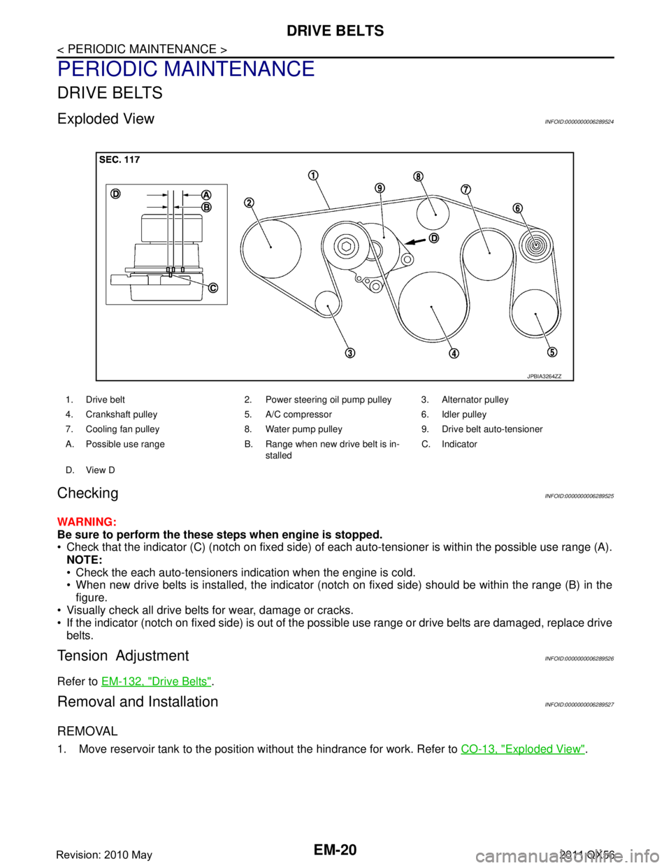
Exploded ViewINFOID:0000000006289524
CheckingINFOID:0000000006289525
WARNING:
Be sure to perform the these steps when engine is stopped.
Check that the indicator (C) (notch on fixed side) of each auto-tensioner is within the possible use range (A).
NOTE:
Check the each auto-tensioners indication when the engine is cold.
When new drive belts is installed, the indicator (notch on fixed side) should be within the range (B) in the\
figure.
Visually check all drive belts for wear, damage or cracks.
If the indicator (notch on fixed side) is out of the possible use range or drive belts are damaged, replace drive
belts.
Tension AdjustmentINFOID:0000000006289526
Refer to EM-132, "Drive Belts".
Removal and InstallationINFOID:0000000006289527
REMOVAL
1. Move reservoir tank to the position without the hindrance for work. Refer to CO-13, "Exploded View".
1. Drive belt 2. Power steering oil pump pulley 3. Alternator pulley
4. Crankshaft pulley 5. A/C compressor 6. Idler pulley
7. Cooling fan pulley 8. Water pump pulley 9. Drive belt auto-tensioner
A. Possible use range B. Range when new drive belt is in-
stalledC. Indicator
D. View D
JPBIA3264ZZ
Revision: 2010 May2011 QX56
Page 2602 of 5598

EM-40
< REMOVAL AND INSTALLATION >
EXHAUST MANIFOLD AND THREE WAY CATALYST
EXHAUST MANIFOLD AND THREE WAY CATALYST
Exploded ViewINFOID:0000000006289550
Removal and InstallationINFOID:0000000006289551
REMOVAL
WARNING:
Perform the work when the exhaust and cooling system have cooled sufficiently.
1. Drain engine coolant from radiator. Refer to CO-8, "
Draining".
CAUTION:
Perform this step when the engine is cold.
Never spill engine coolant on drive belt.
2. Remove reservoir tank. Refer to CO-13, "
Exploded View".
3. Remove drive belt. Refer to EM-20, "
Removal and Installation".
4. Remove power steering oil pump. Refer to ST-48, "
Exploded View".
5. Remove radiator. Refer to CO-13, "
Exploded View".
6. Remove front under cover. Refer to EXT-25, "
Exploded View".
7. Remove front wheels and tires. Refer to WT-64, "
Exploded View".
8. Remove A/C compressor. Refer to HA-30, "
Exploded View".
9. Remove alternator and alternator bracket. Refer to CHG-25, "
Exploded View".
10. Remove exhaust front tube (bank 1 and bank 2). Refer to EX-5, "
Exploded View".
1. Air fuel ratio sensor 1 (bank 2) 2. Exhaust manifold cover (bank 2) 3. Exhaust manifold and three way cat-
alyst (bank 2)
4. Gasket 5. Exhaust manifold and three way cat-
alyst (bank 1)6. Exhaust manifold cover (bank 1)
7. Air fuel ratio sensor 1 (bank 1)
Refer to GI-4, "
Components" for symbols in the figure.
JSBIA0389GB
Revision: 2010 May2011 QX56
Page 2624 of 5598

EM-62
< REMOVAL AND INSTALLATION >
TIMING CHAIN
Removal and Installation
INFOID:0000000006289566
REMOVAL
1. Release fuel pressure. Refer to EC-153, "Work Procedure".
2. Drain engine coolant from radiator. Refer to CO-8, "
Draining".
3. Remove fan shroud (lower). Refer to CO-13, "
Exploded View".
4. Remove fan bracket. Refer to CO-16, "
Exploded View".
5. Remove drive belt auto-tensioner. Refer to EM-26, "
Exploded View".
6. Remove oil level gauge and oil level gauge guide. Refer to EM-57, "
Exploded View".
7. Move power steering oil pump to the posit ion without the hindrance for work. Refer to ST-48, "
Exploded
View".
8. Remove alternator, alternator bracket and alternator stay. Refer to CHG-25, "
Exploded View".
9. Move power steering reservoir tank to the position without the hindrance for work, and then remove Res- ervoir tank bracket. Refer to ST-54, "
Exploded View".
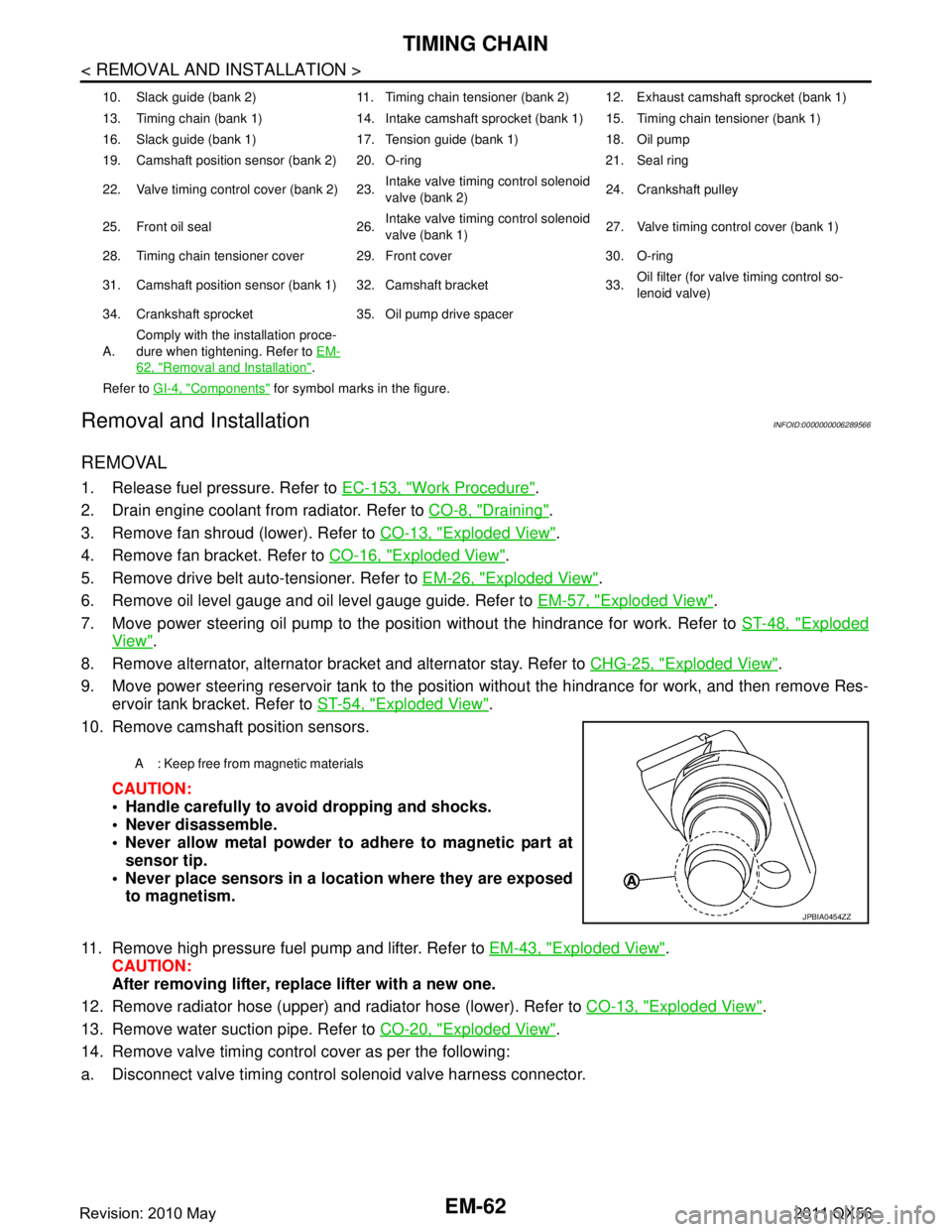
10. Remove camshaft position sensors.
CAUTION:
Handle carefully to avoid dropping and shocks.
Never disassemble.
Never allow metal powder to adhere to magnetic part atsensor tip.
Never place sensors in a lo cation where they are exposed
to magnetism.
11. Remove high pressure fuel pump and lifter. Refer to EM-43, "
Exploded View".
CAUTION:
After removing lifter, replace lifter with a new one.
12. Remove radiator hose (upper) and radiator hose (lower). Refer to CO-13, "
Exploded View".
13. Remove water suction pipe. Refer to CO-20, "
Exploded View".
14. Remove valve timing control cover as per the following:
a. Disconnect valve timing control solenoid valve harness connector.
10. Slack guide (bank 2) 11. Timing chain tensioner (bank 2) 12. Exhaust camshaft sprocket (bank 1)
13. Timing chain (bank 1) 14. Intake camshaft sprocket (bank 1) 15. Timing chain tensioner (bank 1)
16. Slack guide (bank 1) 17. Tension guide (bank 1) 18. Oil pump
19. Camshaft position sensor (bank 2) 20. O-ring 21. Seal ring
22. Valve timing control cover (bank 2) 23. Intake valve timing control solenoid
valve (bank 2)24. Crankshaft pulley
25. Front oil seal 26. Intake valve timing control solenoid
valve (bank 1)27. Valve timing control cover (bank 1)
28. Timing chain tensioner cover 29. Front cover 30. O-ring
31. Camshaft position sensor (bank 1) 32. Camshaft bracket 33. Oil filter (for valve timing control so-
lenoid valve)
34. Crankshaft sprocket 35. Oil pump drive spacer
A. Comply with the installation proce-
dure when tightening. Refer to
EM-
62, "Removal and Installation".
Refer to GI-4, "
Components" for symbol marks in the figure.
A : Keep free from magnetic materials
JPBIA0454ZZ
Revision: 2010 May2011 QX56