2011 INFINITI QX56 air bleeding
[x] Cancel search: air bleedingPage 654 of 5598
![INFINITI QX56 2011 Factory Service Manual
ABS ACTUATOR AND ELECTRIC UNIT (CONTROL UNIT)BRC-137
< REMOVAL AND INSTALLATION > [WITH VDC]
C
D
E
G H
I
J
K L
M A
B
BRC
N
O P
ABS ACTUATOR AND ELECTRIC UNIT (CONTROL UNIT)
Removal and InstallationI INFINITI QX56 2011 Factory Service Manual
ABS ACTUATOR AND ELECTRIC UNIT (CONTROL UNIT)BRC-137
< REMOVAL AND INSTALLATION > [WITH VDC]
C
D
E
G H
I
J
K L
M A
B
BRC
N
O P
ABS ACTUATOR AND ELECTRIC UNIT (CONTROL UNIT)
Removal and InstallationI](/manual-img/42/57033/w960_57033-653.png)
ABS ACTUATOR AND ELECTRIC UNIT (CONTROL UNIT)BRC-137
< REMOVAL AND INSTALLATION > [WITH VDC]
C
D
E
G H
I
J
K L
M A
B
BRC
N
O P
ABS ACTUATOR AND ELECTRIC UNIT (CONTROL UNIT)
Removal and InstallationINFOID:0000000006222676
REMOVAL
1. Remove hydraulic booster assembly. Refer to BR-29, "Removal and Installation".
CAUTION:
After replacing the hydraulic booster assembly or motor/accumulator assembly, always follow the
accumulator disposal procedure to discard the hydraulic booster assembly or motor/accumulator
assembly. Refer to BR-33, "
Disposal".
2. Remove ABS actuator and electric unit (control unit). Refer to BR-30, "
Disassembly and Assembly".
INSTALLATION
Note the following, and install in the reverse order of removal.
When installing brake tube, tighten to the specified torque using a crowfoot and torque wrench so that flare
nut and brake tube are not damaged. Refer to BR-22, "
FRONT : Exploded View".
Never remove and install hydraulic booster assembly by holding harness.
Bleed air from brake piping after installation. Refer to BR-11, "
Bleeding Brake System".
Never apply excessive impact to hydraulic booster assembly, such as by dropping it.
Check that connector is fully locked after hydraul ic booster assembly harness connector is installed.
Perform decel G sensor calibration when hydraulic boos ter assembly [ABS actuator and electric unit (control
unit)] is replaced. Refer to BRC-66, "
Work Procedure".
Revision: 2010 May2011 QX56
Page 3698 of 5598

MA-28
< PERIODIC MAINTENANCE >
CHASSIS MAINTENANCE
BRAKE FLUID LEVEL AND LEAKS : Inspection
INFOID:0000000006220939
Check that the fluid level in the sub tank is within the specified range (MAX – MIN lines).
CAUTION:
Turn OFF the ignition switch an d depress the brake pedal 20 times or more to check brake fluid level.
NOTE:
Since brake fluid is in the accumulator in pressurized condition, the reservoir tank brake fluid level should be
lower than the MAX line.
Visually check for any brake fluid leakage around the reservoir tank.
Check the brake system for any leakage if the fl uid level is extremely low (lower than MIN).
Check the brake system for fluid leakage if the warn ing lamp remains illuminated even after the parking
brake is released.
Check the sub tank for the mixing of foreign ma tter (e.g. dust) and oils other than brake fluid.
BRAKE LINES AND CABLES
BRAKE LINES AND CABLES : InspectionINFOID:0000000006220940
1. Check brake line (tubes and hoses) for cracks, deterioration or other damage. Replace any damaged
parts.
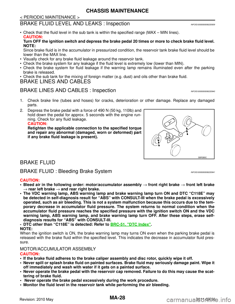
2. Depress the brake pedal with a force of 490 N (50 kg, 110lb) and hold down the pedal for approx. 5 seconds with the engine run-
ning. Check for any fluid leakage.
CAUTION:
Retighten the applicable conn ection to the specified torque
and repair any abnormal (damag ed, worn or deformed) part
if any brake fluid leakage is present).
BRAKE FLUID
BRAKE FLUID : Bleeding Brake SystemINFOID:0000000006220941
CAUTION:
Bleed air in the following order: motor/accumulator assembly → front right brake → front left brake
→ rear left brake → and rear right brake.
The VDC warning lamp, ABS warning lamp and br ake warning lamp turn ON and DTC “C118E” may
be detected in self-diagnosis r esult for “ABS” with CONSULT-II I when the brake pedal is excessively
operated, such as air bleeding. Thi s is not a system malfunction becau se this occurs due to the tem-
porary decrease in accumulator fl uid pressure. The system returns to normal condition when the
accumulator fluid pressure reaches the specified pressu re with the ignition switch ON and the VDC
warning lamp, ABS warning lamp, and brake warnin g lamp turn OFF. After these steps, erase self-
diagnosis results for “ABS” with CONSULT-III.
- DTC other than “C118E” is detected: Refer to BRC-51, "
DTC Index".
NOTE:
When the ignition switch is ON, the brake warning la mp may turns ON even when the parking brake pedal is
released with the brake fluid within the specified level. This indicates the decrease in accumulator fluid pres-
sure.
MOTOR/ACCUMULATOR ASSEMBLY
CAUTION:
If the brake fluid adheres to the brake caliper assembly and disc rotor, quickly wipe it off.
Never spill or splash brake fluid on painted surfaces. Brake fluid may seriously damage paint. Wipe it
off immediately and wash with wate r if it gets on a painted surface.
Never operate the brake pedal with the reservoir cap removed. Failure to do this may cause the scat-
tering of brake fluid.
Never operate the brake pedal excessively during the work procedure.
Monitor the fluid level in the reservoir tank while performing the air bleeding.
SBR389C
Revision: 2010 May2011 QX56
Page 3699 of 5598

CHASSIS MAINTENANCEMA-29
< PERIODIC MAINTENANCE >
C
DE
F
G H
I
J
K L
M B
MA
N
O A
Bleed air in the following
order: motor/accumulator assembly → front right brake → front left brake
→ rear left brake → and rear right brake.
1. Turn the ignition switch OFF.
2. Depress the brake pedal 20 times or more.
3. Check that there is no foreign material in t he reservoir tank, and refill with new brake fluid.
CAUTION:
Never reuse drained brake fluid.
Never allow oils other than brake fl uid to enter the reservoir tank.
4. Turn the ignition switch ON. NOTE:
The motor is activated and automatically stops.
5. Turn the ignition switch OFF.
6. Depress the brake pedal 20 times or more. NOTE:
The pressure loss in the accumulator results in a large brake pedal stroke. In addition to this, the brake
pedal depression becomes lighter in initial stage.
7. Repeat steps 4 to 6 for 5 times.
8. Turn the ignition switch ON to check that the time between motor activation and automatic stop is less
than 18 seconds. If the time is 18 seconds or more, repeat from Step 4 to 8.
FRONT BRAKE
CAUTION:
If the brake fluid adheres to the brake caliper assembly and disc rotor, quickly wipe it off.
Never spill or splash brake fluid on painted surfaces. Brake fluid may seriously damage paint. Wipe it
off immediately and wash with wate r if it gets on a painted surface.
Never operate the brake pedal with the reservoir cap removed. Failure to do this may cause the scat-
tering of brake fluid.
Never operate the brake pedal excessively during the work procedure.
Monitor the fluid level in the reservoir tank while performing the air bleeding.
Bleed air in the following order: motor/accumulator assembly → front right brake → front left brake
→ rear left brake → and rear right brake.
1. Turn the ignition switch OFF.
2. Depress the brake pedal 20 times or more. NOTE:
The pressure loss in the accumulator results in a large brake pedal stroke. In addition to this, the brake
pedal depression becomes lighter in initial stage.
3. Check that there is no foreign material in t he reservoir tank, and refill with new brake fluid.
CAUTION:
Never reuse drained brake fluid.
Never allow oils other than brake fl uid to enter the reservoir tank.
4. Turn the ignition switch ON.
5. Connect a vinyl tube to the bleed valve.
6. Depress the brake pedal and loosen the bleeder valve.
7. Repeat steps 1 to 6 until all of the air is out of the brake line and tighten the air bleeder to the specified
torque with the brake pedal depressed. Refer to BR-36, "
BRAKE CALIPER ASSEMBLY : Exploded View".
8. Check that no drag feel is present for the front disc brake. Refer to BR-39, "
BRAKE CALIPER ASSEMBLY
: Inspection".
9. Check each item of brake pedal. Adjust it if t he measurement value is not the standard. Refer to BR-7,
"Inspection and Adjustment".
REAR BRAKE
CAUTION:
If the brake fluid adheres to the brake caliper assembly and disc rotor, quickly wipe it off.
Never spill or splash brake fluid on painted surfaces. Brake fluid may seriously damage paint. Wipe it
off immediately and wash with wate r if it gets on a painted surface.
Never operate the brake pedal with the reservoir cap removed. Failure to do this may cause the scat-
tering of brake fluid.
Revision: 2010 May2011 QX56
Page 3700 of 5598

MA-30
< PERIODIC MAINTENANCE >
CHASSIS MAINTENANCE
Never operate the brake pedal excessively during the work procedure.
Monitor the fluid level in the reservoir tank while performing the air bleeding.
Bleed air in the following order: motor/accumulator assembly → front right brake → front left brake
→ rear left brake → and rear right brake.
1. Turn the ignition switch OFF.
2. Depress the brake pedal 20 times or more. NOTE:
The pressure loss in the accumulator results in a large brake pedal stroke. In addition to this, the brake
pedal depression becomes lighter in initial stage.
3. Check that there is no foreign material in the reservoir tank, and refill with new brake fluid. CAUTION:
Never reuse drained brake fluid.
Never allow oils other than brake fluid to enter the reservoir tank.
4. Turn the ignition switch ON.
5. Connect a vinyl tube to the bleed valve.
6. Depress the brake pedal and loosen the bleeder valve.
7. Depress and hold the brake pedal depression to dischar ge 100 cc of brake fluid before tightening the air
bleeder to the specified torque. Refer to BR-42, "
BRAKE CALIPER ASSEMBLY : Exploded View".
NOTE:
Since brake fluid is conveyed by the motor, the brake pedal is not necessarily depressed.
8. Release the brake pedal.
9. Repeat steps 1 to 8 until all of the air is out of the brake line and tighten the air bleeder to the specified
torque with the brake pedal depressed. Refer to BR-42, "
BRAKE CALIPER ASSEMBLY : Exploded View".
10. Check that no drag feel is present for the rear disc brake. Refer to BR-45, "
BRAKE CALIPER ASSEMBLY
: Inspection".
11. Check each item of brake pedal. Adjust it if t he measurement value is not the standard. Refer to BR-7,
"Inspection and Adjustment".
BRAKE FLUID LEVEL ADJUSTMENT AFTER AIR BLEEDING
1. Turn the ignition switch OFF.
2. Depress the brake pedal 20 times or more.
NOTE:
The pressure loss in the accumulator results in a large brake pedal stroke. In addition to this, the brake
pedal depression becomes lighter in initial stage.
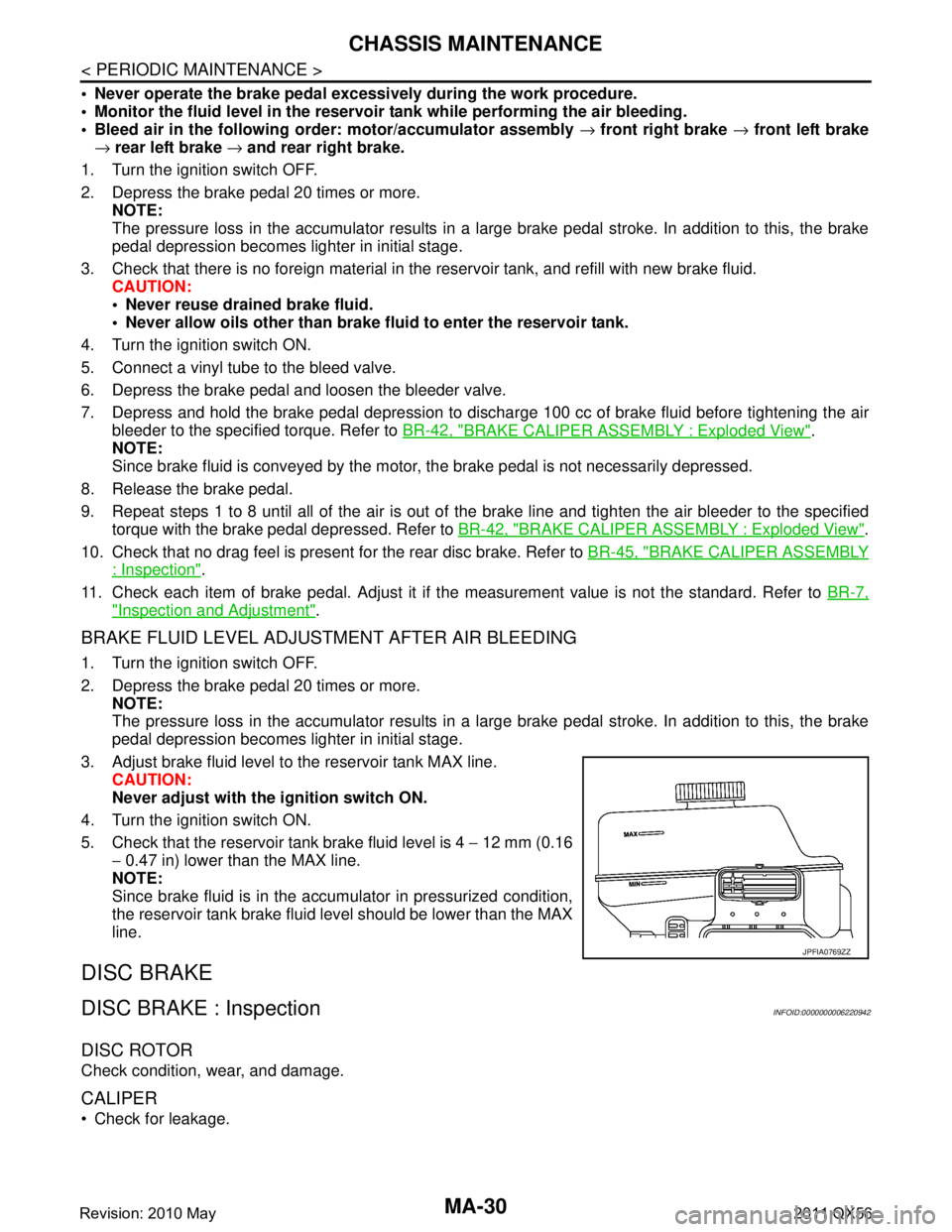
3. Adjust brake fluid level to the reservoir tank MAX line. CAUTION:
Never adjust with the ignition switch ON.
4. Turn the ignition switch ON.
5. Check that the reservoir tank brake fluid level is 4 − 12 mm (0.16
− 0.47 in) lower than the MAX line.
NOTE:
Since brake fluid is in the accumulator in pressurized condition,
the reservoir tank brake fluid level should be lower than the MAX
line.
DISC BRAKE
DISC BRAKE : InspectionINFOID:0000000006220942
DISC ROTOR
Check condition, wear, and damage.
CALIPER
Check for leakage.
JPFIA0769ZZ
Revision: 2010 May2011 QX56
Page 4361 of 5598

SCS-1
SUSPENSION
C
DF
G H
I
J
K L
M
SECTION SCS
A
B
SCS
N
O PCONTENTS
SUSPENSION CONTROL SYSTEM
HBMC
PRECAUTION ................ ...............................
4
PRECAUTIONS .............................................. .....4
Precaution for Supplemental Restraint System
(SRS) "AIR BAG" and "SEAT BELT PRE-TEN-
SIONER" ............................................................. ......
4
Precaution Necessary for Steering Wheel Rota-
tion after Battery Disconnect .....................................
4
Precaution for Procedure without Cowl Top Cover ......5
Precaution for Hydraulic Body-Motion Control
System ......................................................................
5
PREPARATION ............................................6
PREPARATION .............................................. .....6
Special Service Tools .......................................... ......6
Commercial Service Tools ........................................6
SYSTEM DESCRIPTION ..............................7
DESCRIPTION ............................................... .....7
Description .......................................................... ......7
COMPONENT PARTS ........................................8
Component Parts Location .................................. ......8
Component Description .............................................8
STRUCTURE AND OPERATION ........................9
Hydraulic Body-Motion Control System .............. ......9
Shock Absorber .........................................................9
PPMU ......................................................................10
Accumulator ............................................................11
PPMU Pipe ..............................................................11
SYSTEM .............................................................12
System Diagram .................................................. ....12
System Description .................................................12
Component Description ...........................................14
BASIC INSPECTION ...................................15
CHECK SYSTEM PRESSURE .........................15
Work Procedure ................................................... ....15
PRESSURE REDUCING METHOD ..................17
Work Procedure .......................................................17
AIR BLEEDING METHOD ................................18
Work Procedure .......................................................18
CHECK INTERNAL LEAKAGE ........................20
Work Procedure .......................................................20
CHECK FOR MALFUNCTION ..........................22
Work Procedure .......................................................22
CHECK SHOCK ABSORBER FOR MAL-
FUNCTION ....................................... .................
24
Work Procedure ................................................... ....24
CHECK ORIFICE FOR CLOGGING .................27
Work Procedure .......................................................27
SYMPTOM DIAGNOSIS ..............................29
DIFFERENCE IN APPEARANCE .....................29
Description ........................................................... ....29
Inspection Procedure ...............................................29
LARGE ROLL ANGLE ......................................30
Description ...............................................................30
Inspection Procedure ...............................................30
REMOVAL AND INSTALLATION ...............31
HYDRAULIC BODY-MOTION CONTROL
SYSTEM ............................................................
31
Hydraulic Piping ................................................... ....31
FRONT TUBE ASSEMBLY .......................................31
FRONT TUBE ASSEMBLY : Exploded View ...... ....32
FRONT TUBE ASSEMBLY : Removal and Instal-
lation ........................................................................
32
FRONT TUBE ASSEMBLY : Inspection ..................34
Revision: 2010 May2011 QX56
Page 4365 of 5598
![INFINITI QX56 2011 Factory Service Manual
PRECAUTIONSSCS-5
< PRECAUTION > [HBMC]
C
D
F
G H
I
J
K L
M A
B
SCS
N
O P
5. When the repair work is completed, re-connect both battery cables. With the brake pedal released, turn
the push-button ign INFINITI QX56 2011 Factory Service Manual
PRECAUTIONSSCS-5
< PRECAUTION > [HBMC]
C
D
F
G H
I
J
K L
M A
B
SCS
N
O P
5. When the repair work is completed, re-connect both battery cables. With the brake pedal released, turn
the push-button ign](/manual-img/42/57033/w960_57033-4364.png)
PRECAUTIONSSCS-5
< PRECAUTION > [HBMC]
C
D
F
G H
I
J
K L
M A
B
SCS
N
O P
5. When the repair work is completed, re-connect both battery cables. With the brake pedal released, turn
the push-button ignition switch from ACC position to ON position, then to LOCK position. (The steering
wheel will lock when the push-button ignition switch is turned to LOCK position.)
6. Perform self-diagnosis check of a ll control units using CONSULT-III.
Precaution for Procedure without Cowl Top CoverINFOID:0000000006256138
When performing the procedure after removing cowl top cover, cover
the lower end of windshield with urethane, etc.
Precaution for Hydraulic Body-Motion Control SystemINFOID:0000000006255996
WARNING:
Always check the piping for loose co nnections, damage, or twists before starting operation, since
pressure in hydraulic circuit becom es high during air bleeding operation.
When repairing or replacing a malfunctioning pa rt, always release pressure from hydraulic circuit,
since dangerous conditions may be created when oil leakage occurs during air bleeding operation.
Clean surrounding areas of oil inlet and air bleeder usi ng steam before starting operation, since there may
be mud on it.
Always decrease pressure when removing a system related part, since system pressure is high.
Seal the removed part using vinyl tape for preventi ng dirt from getting on or entering the removed part.
Check system pressure again 1 day or more after bleeding operation is complete, since system pressure may decrease when air bleeding is insufficient.
Use Genuine NISSAN Hydraulic Suspension Fluid for suspension fluid.
Never reuse drained suspension fluid.
Check for suspension fluid leakage after removing a system-related part.
PIIB3706J
Revision: 2010 May2011 QX56
Page 4366 of 5598
![INFINITI QX56 2011 Factory Service Manual
SCS-6
< PREPARATION >[HBMC]
PREPARATION
PREPARATION
PREPARATION
Special Service ToolsINFOID:0000000006255997
The actual shapes of Kent-Moore tool
s may differ from those of special service tools illu INFINITI QX56 2011 Factory Service Manual
SCS-6
< PREPARATION >[HBMC]
PREPARATION
PREPARATION
PREPARATION
Special Service ToolsINFOID:0000000006255997
The actual shapes of Kent-Moore tool
s may differ from those of special service tools illu](/manual-img/42/57033/w960_57033-4365.png)
SCS-6
< PREPARATION >[HBMC]
PREPARATION
PREPARATION
PREPARATION
Special Service ToolsINFOID:0000000006255997
The actual shapes of Kent-Moore tool
s may differ from those of special service tools illustrated here.
Commercial Service ToolsINFOID:0000000006414888
Tool number
(Kent-Moore No.)
Tool name Description
KV40107700
(—)
Suspension oil pump Air bleeding
System diagnosis
KV40108000
(—)
Oil pressure gauge System pressure check
KV40108400
(—)
Leak check plug Shock absorber leakage check
JSEIA0183ZZ
JSEIA0184ZZ
JSEIA0185ZZ
Tool name
Description
Power tool Loosening bolts and nuts
PBIC0190E
Revision: 2010 May2011 QX56
Page 4374 of 5598
![INFINITI QX56 2011 Factory Service Manual
SCS-14
< SYSTEM DESCRIPTION >[HBMC]
SYSTEM
Component Description
INFOID:0000000006256008
JSEIA0178GB
Component parts Description
Needle valve A Needle valve for oil filling or trouble diagnosis. It i INFINITI QX56 2011 Factory Service Manual
SCS-14
< SYSTEM DESCRIPTION >[HBMC]
SYSTEM
Component Description
INFOID:0000000006256008
JSEIA0178GB
Component parts Description
Needle valve A Needle valve for oil filling or trouble diagnosis. It i](/manual-img/42/57033/w960_57033-4373.png)
SCS-14
< SYSTEM DESCRIPTION >[HBMC]
SYSTEM
Component Description
INFOID:0000000006256008
JSEIA0178GB
Component parts Description
Needle valve A Needle valve for oil filling or trouble diagnosis. It is usually closed.
Needle valve B Needle valve for trouble diagnosis. It is usually open.
Needle valve C Needle valve for oil filling or trouble diagnosis. It is usually closed.
Needle valve D Needle valve for trouble diagnosis. It is usually open.
Needle valve E Needle valve for oil filling or trouble diagnosis. It is usually closed.
Relief valve If system pressure increases, then the orifice becomes clogged and oil flow into PPMU be-
comes disrupted, resulting in a large pressure difference between PPMU and both pipes. In
this case, the relief valve opens to let the oil flow.
Oil injection jack Oil filling inlet
For basic inspection use.
Air bleeder For air bleeding use.
Revision: 2010 May2011 QX56