2011 INFINITI QX56 door lock
[x] Cancel search: door lockPage 3674 of 5598
MA-4
< PERIODIC MAINTENANCE >
GENERAL MAINTENANCE
PERIODIC MAINTENANCE
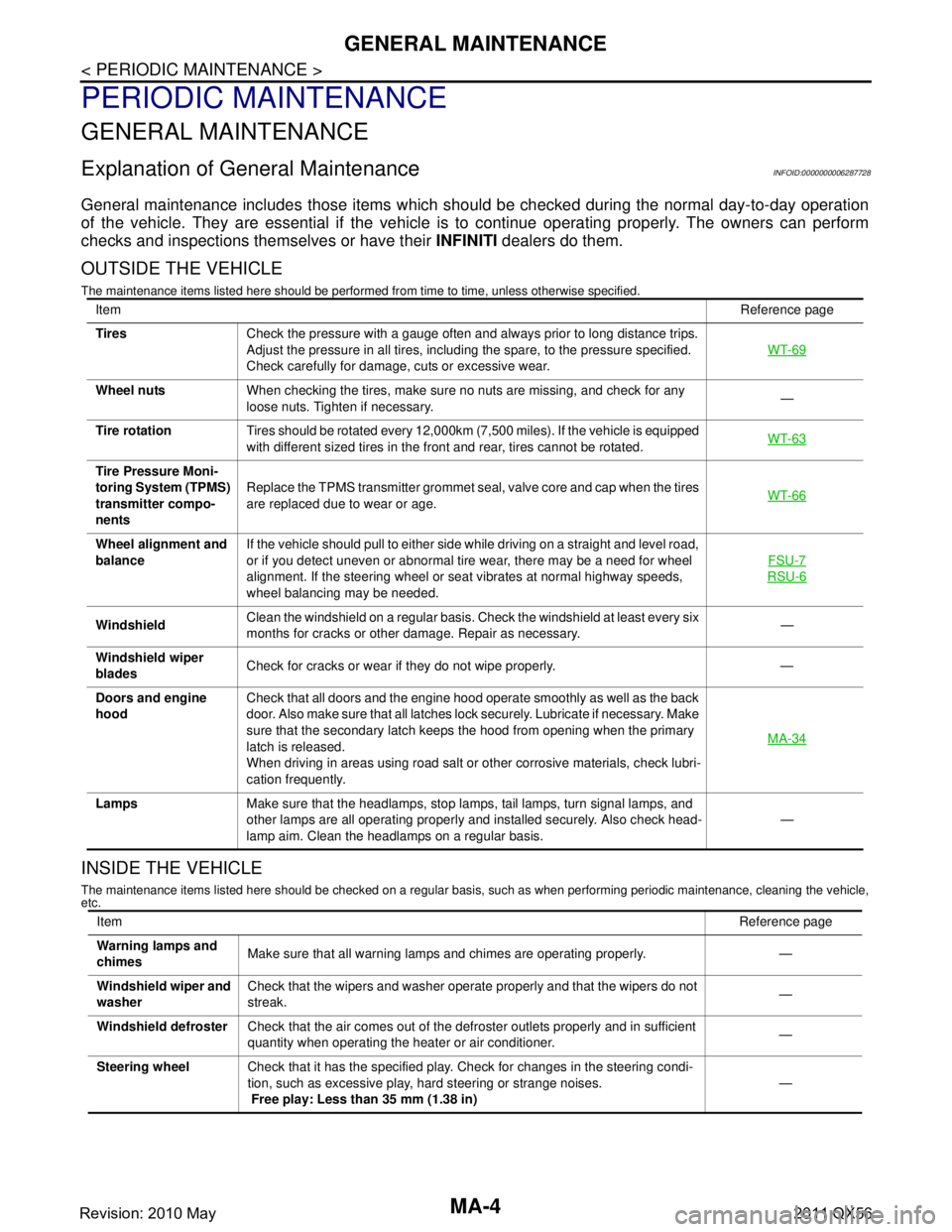
GENERAL MAINTENANCE
Explanation of General MaintenanceINFOID:0000000006287728
General maintenance includes those items which shoul d be checked during the normal day-to-day operation
of the vehicle. They are essential if the vehicle is to continue operating properly. The owners can perform
checks and inspections themselves or have their INFINITI dealers do them.
OUTSIDE THE VEHICLE
The maintenance items listed here should be performed fr om time to time, unless otherwise specified.
INSIDE THE VEHICLE
The maintenance items listed here should be checked on a regular basis, such as when performing periodic maintenance, cleaning the vehicle,
etc.
Item Reference page
Tires Check the pressure with a gauge often and always prior to long distance trips.
Adjust the pressure in all tires, including the spare, to the pressure specified.
Check carefully for damage, cuts or excessive wear. WT-69
Wheel nuts
When checking the tires, make sure no nuts are missing, and check for any
loose nuts. Tighten if necessary. —
Tire rotation Tires should be rotated every 12,000km (7,500 miles). If the vehicle is equipped
with different sized tires in the front and rear, tires cannot be rotated. WT-63
Tire Pressure Moni-
toring System (TPMS)
transmitter compo-
nentsReplace the TPMS transmitter grommet seal, valve core and cap when the tires
are replaced due to wear or age.
WT-66
Wheel alignment and
balanceIf the vehicle should pull to either side while driving on a straight and level road,
or if you detect uneven or abnormal tire wear, there may be a need for wheel
alignment. If the steering wheel or seat vibrates at normal highway speeds,
wheel balancing may be needed. FSU-7
RSU-6
Windshield
Clean the windshield on a regular basis. Check the windshield at least every six
months for cracks or other damage. Repair as necessary. —
Windshield wiper
blades Check for cracks or wear if they do not wipe properly. —
Doors and engine
hood Check that all doors and the engine hood operate smoothly as well as the back
door. Also make sure that all latches lock securely. Lubricate if necessary. Make
sure that the secondary latch keeps the hood from opening when the primary
latch is released.
When driving in areas using road salt or other corrosive materials, check lubri-
cation frequently. MA-34
Lamps
Make sure that the headlamps, stop lamps, tail lamps, turn signal lamps, and
other lamps are all operating properly and installed securely. Also check head-
lamp aim. Clean the headlamps on a regular basis. —
Item
Reference page
Warning lamps and
chimes Make sure that all warning lamps and chimes are operating properly. —
Windshield wiper and
washer Check that the wipers and washer operate properly and that the wipers do not
streak.
—
Windshield defroster Check that the air comes out of the defroster outlets properly and in sufficient
quantity when operating the heater or air conditioner. —
Steering wheel Check that it has the specified play. Check for changes in the steering condi-
tion, such as excessive play, hard steering or strange noises.
Free play: Less than 35 mm (1.38 in) —
Revision: 2010 May2011 QX56
Page 3704 of 5598
MA-34
< PERIODIC MAINTENANCE >
BODY MAINTENANCE
BODY MAINTENANCE
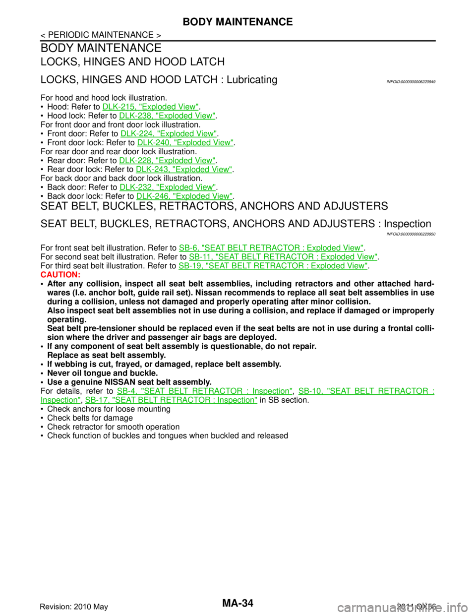
LOCKS, HINGES AND HOOD LATCH
LOCKS, HINGES AND HOOD LATCH : LubricatingINFOID:0000000006220949
For hood and hood lock illustration.
Hood: Refer to DLK-215, "
Exploded View".
Hood lock: Refer to DLK-238, "
Exploded View".
For front door and front door lock illustration.
Front door: Refer to DLK-224, "
Exploded View".
Front door lock: Refer to DLK-240, "
Exploded View".
For rear door and rear door lock illustration.
Rear door: Refer to DLK-228, "
Exploded View".
Rear door lock: Refer to DLK-243, "
Exploded View".
For back door and back door lock illustration.
Back door: Refer to DLK-232, "
Exploded View".
Back door lock: Refer to DLK-246, "
Exploded View".
SEAT BELT, BUCKLES, RETRACTORS, ANCHORS AND ADJUSTERS
SEAT BELT, BUCKLES, RETRACTORS, ANCHORS AND ADJUSTERS : Inspection
INFOID:0000000006220950
For front seat belt illustration. Refer to SB-6, "SEAT BELT RETRACTOR : Exploded View".
For second seat belt illustration. Refer to SB-11, "
SEAT BELT RETRACTOR : Exploded View".
For third seat belt illustration. Refer to SB-19, "
SEAT BELT RETRACTOR : Exploded View".
CAUTION:
After any collision, inspect all seat belt assembli es, including retractors and other attached hard-
wares (I.e. anchor bolt, guide ra il set). Nissan recommends to replace all seat belt assemblies in use
during a collision, unless not damaged and pr operly operating after minor collision.
Also inspect seat belt assemblies not in use during a collision, and replace if damaged or improperly
operating.
Seat belt pre-tensioner should be replaced even if th e seat belts are not in use during a frontal colli-
sion where the driver and passenger air bags are deployed.
If any component of seat belt assembl y is questionable, do not repair.
Replace as seat belt assembly.
If webbing is cut, frayed, or damaged, replace belt assembly.
Never oil tongue and buckle.
Use a genuine NISSAN seat belt assembly.
For details, refer to SB-4, "
SEAT BELT RETRACTOR : Inspection", SB-10, "SEAT BELT RETRACTOR :
Inspection", SB-17, "SEAT BELT RETRACTOR : Inspection" in SB section.
Check anchors for loose mounting
Check belts for damage
Check retractor for smooth operation
Check function of buckles and tongues when buckled and released
Revision: 2010 May2011 QX56
Page 3706 of 5598

MIR-1
DRIVER CONTROLS
C
DE
F
G H
I
J
K
M
SECTION MIR
A
B
MIR
N
O P
CONTENTS
MIRRORS
PRECAUTION ................ ...............................3
PRECAUTIONS .............................................. .....3
Precaution for Supplemental Restraint System
(SRS) "AIR BAG" and "SEAT BELT PRE-TEN-
SIONER" ............................................................. ......
3
Precaution Necessary for Steering Wheel Rota-
tion after Battery Disconnect .....................................
3
PREPARATION ............................................5
PREPARATION .............................................. .....5
Commercial Service Tools ................................. ......5
SYSTEM DESCRIPTION ..............................6
COMPONENT PARTS ................................... .....6
DOOR MIRROR ..................................................... ......6
DOOR MIRROR : Component Parts Location ..........6
DOOR MIRROR : Component Description ...............6
INSIDE MIRROR .................................................... ......7
INSIDE MIRROR : Component Description ..............7
SYSTEM ..............................................................8
DOOR MIRROR SYSTEM ..................................... ......8
DOOR MIRROR SYSTEM : System Diagram ..........8
DOOR MIRROR SYSTEM : System Description ......8
AUTO ANTI-DAZZLING INSIDE MIRROR SYS-
TEM ........................................................................ ......
9
AUTO ANTI-DAZZLING INSIDE MIRROR SYS-
TEM : System Description .........................................
9
ECU DIAGNOSIS INFORMATION ..............10
DRIVER SEAT CONTROL UNIT, AUTOMAT-
IC DRIVE POSITIONER CONTROL UNIT ..... ....
10
List of ECU Reference ........................................ ....10
WIRING DIAGRAM ......................................11
DOOR MIRROR SYSTEM .................................11
Wiring Diagram .................................................... ....11
AUTO ANTI-DAZZLING INSIDE MIRROR
SYSTEM ............................................................
19
Wiring Diagram - INSIDE MIRROR SYSTEM - ... ....19
BASIC INSPECTION ....... ............................21
DIAGNOSIS AND REPAIR WORKFLOW ........21
Work Flow ............................................................ ....21
DTC/CIRCUIT DIAGNOSIS .........................22
DOOR MIRROR REMOTE CONTROL
SWITCH .............................................................
22
OPEN/CLOSE SWITCH ......................................... ....22
OPEN/CLOSE SWITCH : Component Inspection ....22
SYMPTOM DIAGNOSIS ..............................23
REVERSE INTERLOCK DOOR MIRROR
DOES NOT OPERATE ......................................
23
Diagnosis Procedure ........................................... ....23
SQUEAK AND RATTLE TROUBLE DIAG-
NOSES ..............................................................
24
Work Flow ................................................................24
Inspection Procedure ...............................................26
Diagnostic Worksheet ..............................................28
REMOVAL AND INSTALLATION ...............30
INSIDE MIRROR ...............................................30
Exploded View ..................................................... ....30
Removal and Installation .........................................30
OUTSIDE MIRROR ...........................................32
Exploded View .........................................................32
DOOR MIRROR ASSEMBLY ....................................32
Revision: 2010 May2011 QX56
Page 3713 of 5598

MIR-8
< SYSTEM DESCRIPTION >
SYSTEM
SYSTEM
DOOR MIRROR SYSTEM
DOOR MIRROR SYSTEM : System DiagramINFOID:0000000006257222
DOOR MIRROR SYSTEM : System DescriptionINFOID:0000000006257223
MANUAL FUNCTION
Description
Automatic drive positioner control unit controls door mirror.
Automatic drive positioner control unit inputs changeover switch signal and perform the LH/RH control of
door mirror motor supplying electric power when changeover switch is operated.
Automatic drive positioner control unit inputs mirror s witch signal and supplies electric power to door mirror.
The ignition switch signal (ACC/ON) is transmitted from BCM to driver seat control unit via CAN communica-
tion and from driver seat control unit to automatic drive positioner control unit via UART communication.
Operation Conditions
If the following conditions are not satisfied, operation is not performed.
Ignition switch: ON or ACC
Changeover switch: Select either left or right
REVERSE INTERLOCK DOOR MIRROR SYSTEM
Description
Select either of the door mirror faces by changeover switch, and then set mirror face downward.
When ignition switch is ON position and A/T shift selector is in R position, TCM sends the R signal to driver
seat control unit.
The R signal is transmitted to automatic drive positioner control unit from driver seat control unit via UART
communication.
When the R signal is detected, automatic drive positioner control unit activated mirror motor.
Operation Conditions
If the following conditions are not satisfied, operation is not performed.
Ignition switch: ON
JMLIA0872GB
Revision: 2010 May2011 QX56
Page 3714 of 5598

SYSTEMMIR-9
< SYSTEM DESCRIPTION >
C
DE
F
G H
I
J
K
M A
B
MIR
N
O P
Changeover switch: Select either left or right
A/T shift selector: R position
NOTE:
During the reverse interlock door mirror system, if all of the above conditions are not satisfied, mirror face
returns to original angle.
AUTO ANTI-DAZZLING INSIDE MIRROR SYSTEM
AUTO ANTI-DAZZLING INSIDE MIRRO R SYSTEM : System DescriptionINFOID:0000000006257224
The sensor built in inside mirror detects the bri ghtness of headlight of the vehicle behind and automatically
changes the light transmission to decrease the brightness.
Revision: 2010 May2011 QX56
Page 3728 of 5598
REVERSE INTERLOCK DOOR MIRROR DOES NOT OPERATE
MIR-23
< SYMPTOM DIAGNOSIS >
C
D E
F
G H
I
J
K
M A
B
MIR
N
O P
SYMPTOM DIAGNOSIS
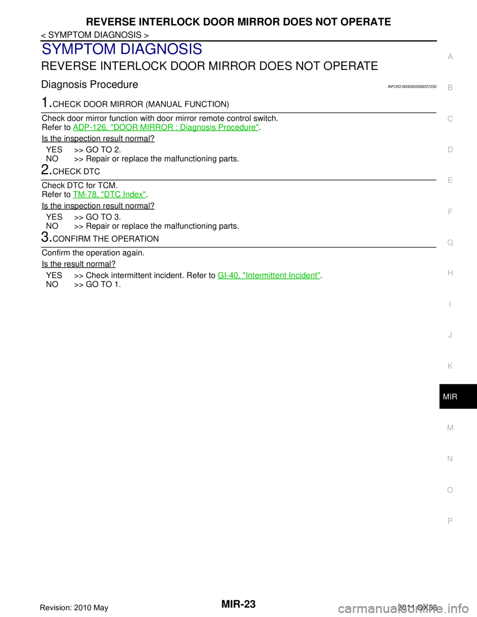
REVERSE INTERLOCK DOOR MI RROR DOES NOT OPERATE
Diagnosis ProcedureINFOID:0000000006257230
1.CHECK DOOR MIRROR (MANUAL FUNCTION)
Check door mirror function with door mirror remote control switch.
Refer to ADP-126, "
DOOR MIRROR : Diagnosis Procedure".
Is the inspection result normal?
YES >> GO TO 2.
NO >> Repair or replace the malfunctioning parts.
2.CHECK DTC
Check DTC for TCM.
Refer to TM-78, "
DTC Index".
Is the inspection result normal?
YES >> GO TO 3.
NO >> Repair or replace the malfunctioning parts.
3.CONFIRM THE OPERATION
Confirm the operation again.
Is the result normal?
YES >> Check intermittent incident. Refer to GI-40, "Intermittent Incident".
NO >> GO TO 1.
Revision: 2010 May2011 QX56
Page 3729 of 5598
MIR-24
< SYMPTOM DIAGNOSIS >
SQUEAK AND RATTLE TROUBLE DIAGNOSES
SQUEAK AND RATTLE TROUBLE DIAGNOSES
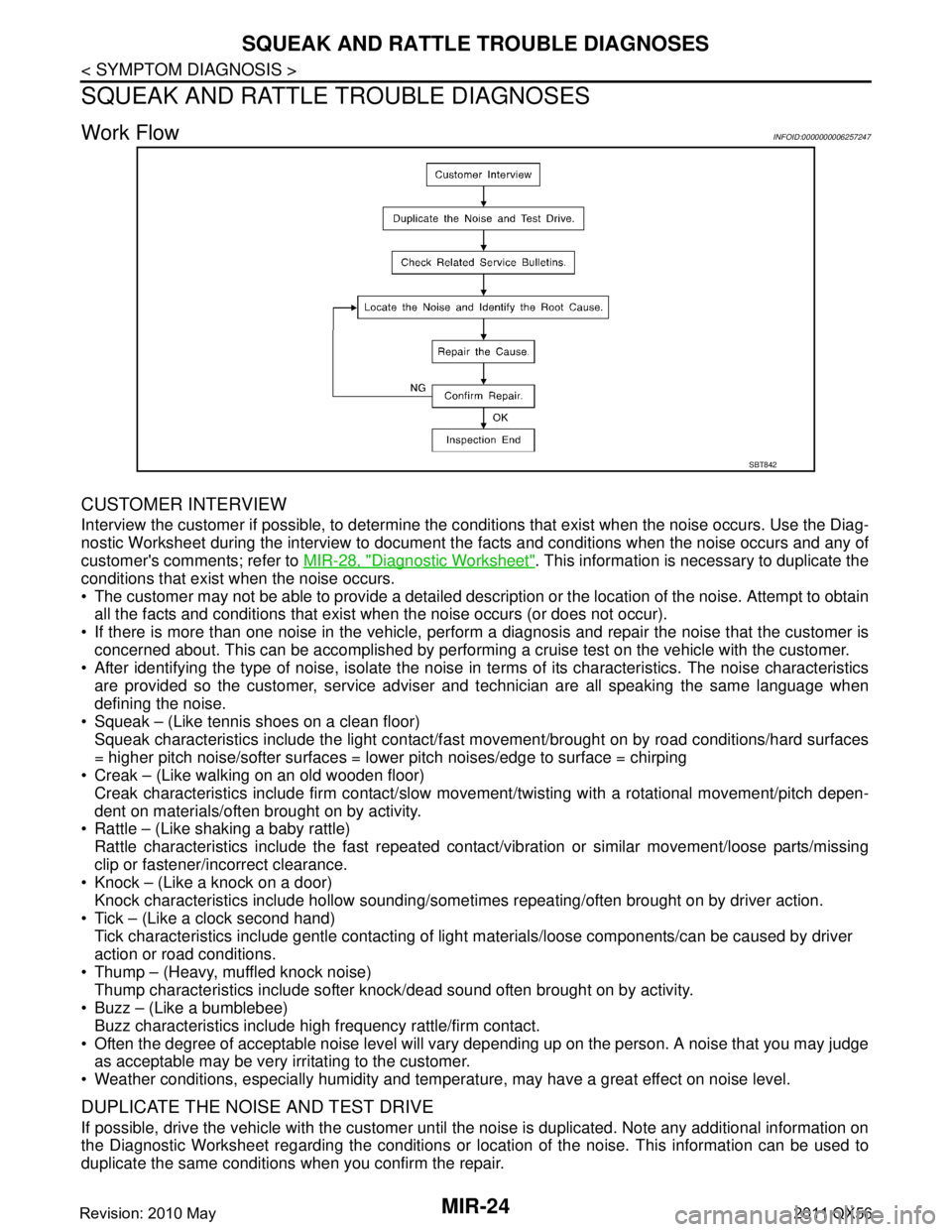
Work FlowINFOID:0000000006257247
CUSTOMER INTERVIEW
Interview the customer if possible, to determine the c onditions that exist when the noise occurs. Use the Diag-
nostic Worksheet during the interview to document t he facts and conditions when the noise occurs and any of
customer's comments; refer to MIR-28, "
Diagnostic Worksheet". This information is necessary to duplicate the
conditions that exist when the noise occurs.
The customer may not be able to provide a detailed description or the location of the noise. Attempt to obtain all the facts and conditions that exist w hen the noise occurs (or does not occur).
If there is more than one noise in the vehicle, perform a diagnosis and repair the noise that the customer is
concerned about. This can be accomplished by performing a cruise test on the vehicle with the customer.
After identifying the type of noise, isolate the noise in terms of its characteristics. The noise characteristics
are provided so the customer, service adviser and technician are all speaking the same language when
defining the noise.
Squeak – (Like tennis shoes on a clean floor)
Squeak characteristics include the light contact/fast movement/brought on by road conditions/hard surfaces
= higher pitch noise/softer surfaces = lower pitch noises/edge to surface = chirping
Creak – (Like walking on an old wooden floor)
Creak characteristics include firm contact/slow mo vement/twisting with a rotational movement/pitch depen-
dent on materials/often brought on by activity.
Rattle – (Like shaking a baby rattle)
Rattle characteristics include the fast repeated contac t/vibration or similar movement/loose parts/missing
clip or fastener/incorrect clearance.
Knock – (Like a knock on a door)
Knock characteristics include hollow sounding/someti mes repeating/often brought on by driver action.
Tick – (Like a clock second hand) Tick characteristics include gentle contacting of light materials/loose components/can be caused by driver
action or road conditions.
Thump – (Heavy, muffled knock noise) Thump characteristics include softer k nock/dead sound often brought on by activity.
Buzz – (Like a bumblebee)
Buzz characteristics include hi gh frequency rattle/firm contact.
Often the degree of acceptable noise level will vary depending up on the person. A noise that you may judge as acceptable may be very irritating to the customer.
Weather conditions, especially humidity and temperat ure, may have a great effect on noise level.
DUPLICATE THE NOISE AND TEST DRIVE
If possible, drive the vehicle with the customer until the noise is duplicated. Note any additional information on
the Diagnostic Worksheet regarding the conditions or lo cation of the noise. This information can be used to
duplicate the same conditions when you confirm the repair.
SBT842
Revision: 2010 May2011 QX56
Page 3730 of 5598
SQUEAK AND RATTLE TROUBLE DIAGNOSESMIR-25
< SYMPTOM DIAGNOSIS >
C
DE
F
G H
I
J
K
M A
B
MIR
N
O P
If the noise can be duplicated easily during the test drive, to help identify the source of the noise, try to dupli-
cate the noise with the vehicle stopped by doing one or all of the following:
1) Close a door.
2) Tap or push/pull around the area where the noise appears to be coming from.
3) Rev the engine.
4) Use a floor jack to recreate vehicle “twist”.
5) At idle, apply engine load (electrical load, half-cl utch on M/T models, drive position on A/T models).
6) Raise the vehicle on a hoist and hit a tire with a rubber hammer.
Drive the vehicle and attempt to duplicate the conditions the customer states exist when the noise occurs.
If it is difficult to duplicate the noise, drive the vehicle slowly on an undulating or rough road to stress the vehicle body.
CHECK RELATED SERVICE BULLETINS
After verifying the customer concern or symptom, che ck ASIST for Technical Service Bulletins (TSBs) related
to that concern or symptom.
If a TSB relates to the symptom, follow the procedure to repair the noise.
LOCATE THE NOISE AND IDENTIFY THE ROOT CAUSE
1. Narrow down the noise to a general area. To help pinpoint the source of the noise, use a listening tool
(Chassis Ear: J-39570, Engine Ear and mechanics stethoscope).
2. Narrow down the noise to a more specific area and identify the cause of the noise by:
Removing the components in the area that you suspect the noise is coming from.
Do not use too much force when removing clips and fasteners, otherwise clips and fastener can be broken
or lost during the repair, resulting in the creation of new noise.
Tapping or pushing/pulling the component that you suspect is causing the noise.
Do not tap or push/pull the component with excessive force, otherwise the noise will be eliminated only tem-
porarily.
Feeling for a vibration with your hand by touching t he component(s) that you suspect is (are) causing the
noise.
Placing a piece of paper between components that you suspect are causing the noise.
Looking for loose components and contact marks. Refer to MIR-26, "
Inspection Procedure".
REPAIR THE CAUSE
If the cause is a loose component, tighten the component securely.
If the cause is insufficient clearance between components:
- Separate components by repositioning or loosening and retightening the component, if possible.
- Insulate components with a suitable insulator such as urethane pads, foam blocks, felt cloth tape or ure-
thane tape. A Nissan Squeak and Rattle Kit (J-43980) is available through your authorized Nissan Parts
Department.
CAUTION:
Do not use excessive force as many components are constructed of plastic and may be damaged.
NOTE:
Always check with the Parts Department for the latest parts information.
The following materials are contained in the Niss an Squeak and Rattle Kit (J-43980). Each item can be
ordered separately as needed.
URETHANE PADS [1.5 mm (0.059 in) thick]
Insulates connectors, harness, etc.
76268-9E005: 100 ×135 mm (3.94 ×5.31 in)/76884-71L01: 60 ×85 mm (2.36 ×3.35 in)/76884-
71L02:15 ×25 mm (0.59 ×0.98 in)
INSULATOR (Foam blocks)
Insulates components from contact. Can be used to fill space behind a panel.
73982-9E000: 45 mm (1.77 in) thick, 50 ×50 mm (1.97 ×1.97 in)/73982-
50Y00: 10 mm (0.39 in) thick, 50 ×50 mm (1.97 ×1.97 in)
INSULATOR (Light foam block)
80845-71L00: 30 mm (1.18 in) thick, 30 ×50 mm (1.18 ×1.97in)
FELT CLOTHTAPE
Used to insulate where movement does not occur. Ideal for instrument panel applications.
68370-4B000: 15 ×25 mm (0.59 ×0.98 in) pad/68239-13E00: 5 mm (0.20 in) wide tape roll
The following materials, not found in the kit, can also be used to repair squeaks and rattles.
UHMW (TEFLON) TAPE
Revision: 2010 May2011 QX56