2011 INFINITI QX56 oil
[x] Cancel search: oilPage 2618 of 5598
EM-56
< REMOVAL AND INSTALLATION >
OIL PAN (LOWER) AND OIL STRAINER
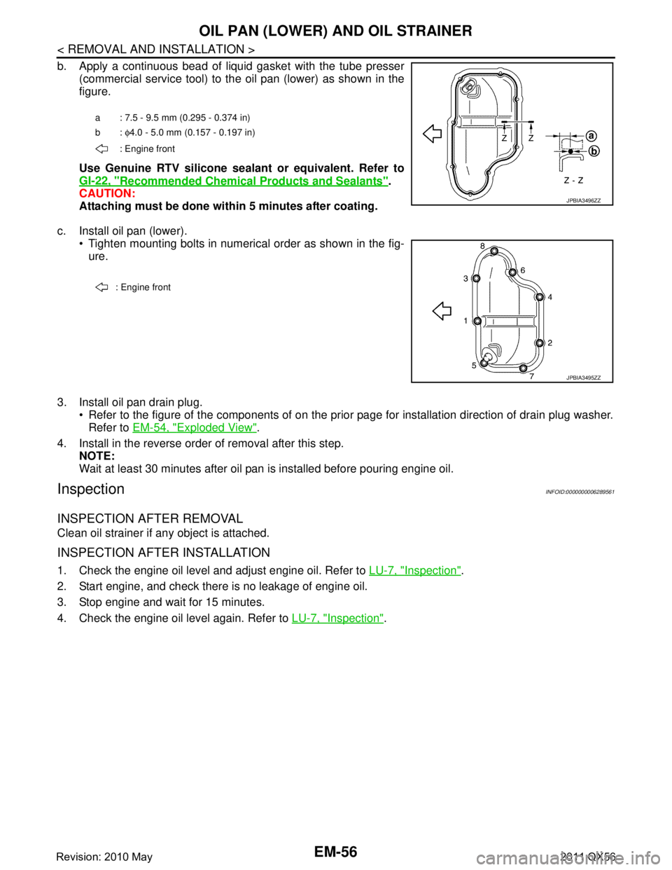
b. Apply a continuous bead of liquid gasket with the tube presser(commercial service tool) to the oil pan (lower) as shown in the
figure.
Use Genuine RTV silicone seal ant or equivalent. Refer to
GI-22, "
Recommended Chemical Products and Sealants".
CAUTION:
Attaching must be done with in 5 minutes after coating.
c. Install oil pan (lower). Tighten mounting bolts in numerical order as shown in the fig-ure.
3. Install oil pan drain plug. Refer to the figure of the components of on the prior page for installation direction of drain plug washer.Refer to EM-54, "
Exploded View".
4. Install in the reverse order of removal after this step. NOTE:
Wait at least 30 minutes after oil pan is installed before pouring engine oil.
InspectionINFOID:0000000006289561
INSPECTION AFTER REMOVAL
Clean oil strainer if any object is attached.
INSPECTION AFTER INSTALLATION
1. Check the engine oil level and adjust engine oil. Refer to LU-7, "Inspection".
2. Start engine, and check there is no leakage of engine oil.
3. Stop engine and wait for 15 minutes.
4. Check the engine oil level again. Refer to LU-7, "
Inspection".
a : 7.5 - 9.5 mm (0.295 - 0.374 in)
b: φ4.0 - 5.0 mm (0.157 - 0.197 in)
: Engine front
JPBIA3496ZZ
: Engine front
JPBIA3495ZZ
Revision: 2010 May2011 QX56
Page 2619 of 5598
OIL PAN (UPPER)EM-57
< REMOVAL AND INSTALLATION >
C
DE
F
G H
I
J
K L
M A
EM
NP
O
OIL PAN (UPPER)
Exploded ViewINFOID:0000000006289562
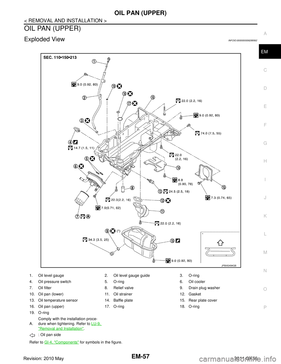
1. Oil level gauge 2. Oil level gauge guide 3. O-ring
4. Oil pressure switch 5. O-ring 6. Oil cooler
7. Oil filter 8. Relief valve 9. Drain plug washer
10. Oil pan (lower) 11. Oil strainer 12. Gasket
13. Oil temperature sensor 14. Baffle plate 15. Rear plate cover
16. Oil pan (upper) 17. O-ring 18. O-ring
19. O-ring
A.
Comply with the installation proce-
dure when tightening. Refer to
LU-9,
"Removal and Installation".
: Oil pan side
Refer to GI-4, "
Components" for symbols in the figure.
JPBIA3494GB
Revision: 2010 May2011 QX56
Page 2620 of 5598
EM-58
< REMOVAL AND INSTALLATION >
OIL PAN (UPPER)
Removal and Installation
INFOID:0000000006289563
REMOVAL
WARNING:
To avoid the danger of being scalded, never drain engine oil when engine is hot.
1. Remove oil filter. Refer to LU-9, "
Removal and Installation".
2. Remove oil cooler. Refer to LU-11, "
Exploded View".
3. Move A/C compressor to the position without the hindrance for work. Refer to HA-30, "
Exploded View".
4. Remove oil level gauge and oil level gauge guide.
5. Remove oil pressure switch and oil temperature sensor if necessary.
6. Remove rear plate cover.
7. Remove protector A and protector B. Refer to SCS-32, "
FRONT TUBE ASSEMBLY : Exploded View".
8. Remove front suspension rear cross member. Refer to TM-205, "
2WD : Exploded View" (2WD models) or
TM-208, "
4WD : Exploded View" (4WD models).
9. Remove steering gear assembly. Refer to ST-41, "
Exploded View".
10. Remove front final drive assembly. Refer to DLN-162, "
Exploded View".
11. Remove oil pan (lower). Refer to EM-54, "
Exploded View".
12. Remove oil strainer. Refer to EM-54, "
Exploded View".
13. Remove bolts fixing oil pan (upper) to transmission assembly.
14. Remove oil pan (upper) as per the following:
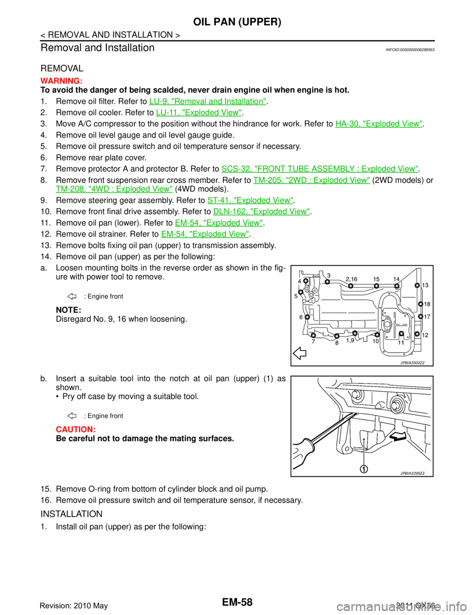
a. Loosen mounting bolts in the reverse order as shown in the fig- ure with power tool to remove.
NOTE:
Disregard No. 9, 16 when loosening.
b. Insert a suitable tool into the notch at oil pan (upper) (1) as shown.
Pry off case by moving a suitable tool.
CAUTION:
Be careful not to damage the mating surfaces.
15. Remove O-ring from bottom of cylinder block and oil pump.
16. Remove oil pressure switch and oil temperature sensor, if necessary.
INSTALLATION
1. Install oil pan (upper) as per the following:
: Engine front
JPBIA3502ZZ
: Engine front
JPBIA2299ZZ
Revision: 2010 May2011 QX56
Page 2621 of 5598
OIL PAN (UPPER)EM-59
< REMOVAL AND INSTALLATION >
C
DE
F
G H
I
J
K L
M A
EM
NP
O
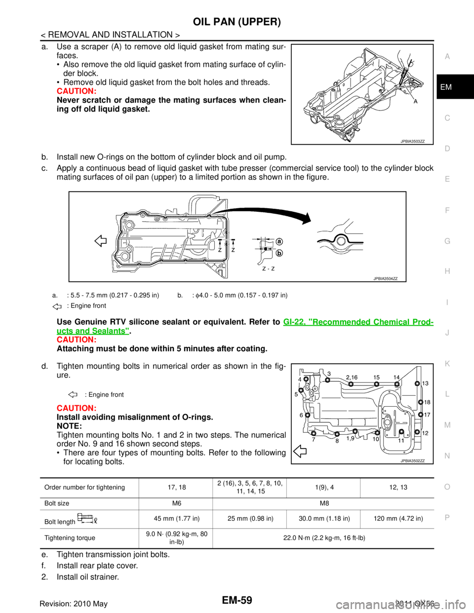
a. Use a scraper (A) to remove old liquid gasket from mating sur-
faces.
Also remove the old liquid gasket from mating surface of cylin-der block.
Remove old liquid gasket from the bolt holes and threads.
CAUTION:
Never scratch or damage th e mating surfaces when clean-
ing off old liquid gasket.
b. Install new O-rings on the bottom of cylinder block and oil pump.
c. Apply a continuous bead of liquid gasket with tube pre sser (commercial service tool) to the cylinder block
mating surfaces of oil pan (upper) to a limited portion as shown in the figure.
Use Genuine RTV silicone sealant or equivalent. Refer to GI-22, "
Recommended Chemical Prod-
ucts and Sealants".
CAUTION:
Attaching must be done with in 5 minutes after coating.
d. Tighten mounting bolts in numerical order as shown in the fig- ure.
CAUTION:
Install avoiding misal ignment of O-rings.
NOTE:
Tighten mounting bolts No. 1 and 2 in two steps. The numerical
order No. 9 and 16 shown second steps.
There are four types of mounting bolts. Refer to the following for locating bolts.
e. Tighten transmission joint bolts.
f. Install rear plate cover.
2. Install oil strainer.
JPBIA3503ZZ
a. : 5.5 - 7.5 mm (0.217 - 0.295 in) b. : φ4.0 - 5.0 mm (0.157 - 0.197 in)
: Engine front
JPBIA3504ZZ
: Engine front
JPBIA3502ZZ
Order number for tightening 17, 18 2 (16), 3, 5, 6, 7, 8, 10,
11, 14, 15 1(9), 4 12, 13
Bolt size M6 M8
Bolt length 45 mm (1.77 in) 25 mm (0.98 in) 30.0 mm (1.18 in) 120 mm (4.72 in)
Tightening torque 9.0 N· (0.92 kg-m, 80
in-lb) 22.0 N·m (2.2 kg-m, 16 ft-lb)
Revision: 2010 May2011 QX56
Page 2622 of 5598
EM-60
< REMOVAL AND INSTALLATION >
OIL PAN (UPPER)
3. Install oil pan (lower). Refer to EM-55, "Removal and Installation".
4. Install in the reverse order of removal. NOTE:
At least 30 minutes after oil pan is installed, pour engine oil.
InspectionINFOID:0000000006289564
INSPECTION AFTER DISASSEMBLY
Clean oil strainer if any object is attached.
INSPECTION AFTER ASSEMBLY
1. Check the engine oil level and adjust engine oil. Refer to LU-9, "Inspection".
2. Start engine, and check there is no leakage of engine oil.
3. Stop engine and wait for 15 minutes.
4. Check the engine oil level again. Refer to LU-9, "
Inspection".
Revision: 2010 May2011 QX56
Page 2624 of 5598
EM-62
< REMOVAL AND INSTALLATION >
TIMING CHAIN
Removal and Installation
INFOID:0000000006289566
REMOVAL
1. Release fuel pressure. Refer to EC-153, "Work Procedure".
2. Drain engine coolant from radiator. Refer to CO-8, "
Draining".
3. Remove fan shroud (lower). Refer to CO-13, "
Exploded View".
4. Remove fan bracket. Refer to CO-16, "
Exploded View".
5. Remove drive belt auto-tensioner. Refer to EM-26, "
Exploded View".
6. Remove oil level gauge and oil level gauge guide. Refer to EM-57, "
Exploded View".
7. Move power steering oil pump to the posit ion without the hindrance for work. Refer to ST-48, "
Exploded
View".
8. Remove alternator, alternator bracket and alternator stay. Refer to CHG-25, "
Exploded View".
9. Move power steering reservoir tank to the position without the hindrance for work, and then remove Res- ervoir tank bracket. Refer to ST-54, "
Exploded View".
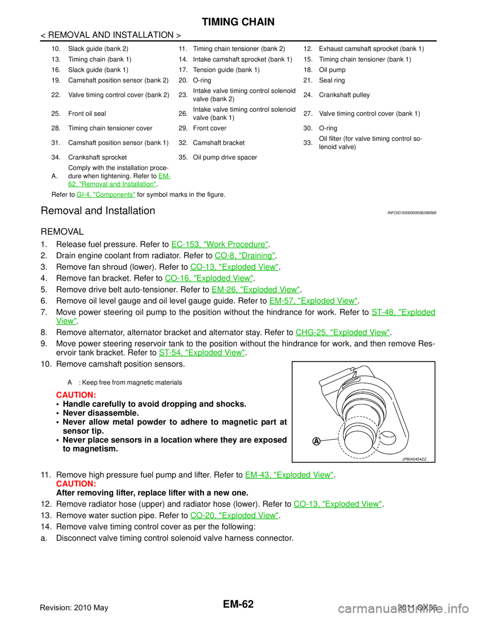
10. Remove camshaft position sensors.
CAUTION:
Handle carefully to avoid dropping and shocks.
Never disassemble.
Never allow metal powder to adhere to magnetic part atsensor tip.
Never place sensors in a lo cation where they are exposed
to magnetism.
11. Remove high pressure fuel pump and lifter. Refer to EM-43, "
Exploded View".
CAUTION:
After removing lifter, replace lifter with a new one.
12. Remove radiator hose (upper) and radiator hose (lower). Refer to CO-13, "
Exploded View".
13. Remove water suction pipe. Refer to CO-20, "
Exploded View".
14. Remove valve timing control cover as per the following:
a. Disconnect valve timing control solenoid valve harness connector.
10. Slack guide (bank 2) 11. Timing chain tensioner (bank 2) 12. Exhaust camshaft sprocket (bank 1)
13. Timing chain (bank 1) 14. Intake camshaft sprocket (bank 1) 15. Timing chain tensioner (bank 1)
16. Slack guide (bank 1) 17. Tension guide (bank 1) 18. Oil pump
19. Camshaft position sensor (bank 2) 20. O-ring 21. Seal ring
22. Valve timing control cover (bank 2) 23. Intake valve timing control solenoid
valve (bank 2)24. Crankshaft pulley
25. Front oil seal 26. Intake valve timing control solenoid
valve (bank 1)27. Valve timing control cover (bank 1)
28. Timing chain tensioner cover 29. Front cover 30. O-ring
31. Camshaft position sensor (bank 1) 32. Camshaft bracket 33. Oil filter (for valve timing control so-
lenoid valve)
34. Crankshaft sprocket 35. Oil pump drive spacer
A. Comply with the installation proce-
dure when tightening. Refer to
EM-
62, "Removal and Installation".
Refer to GI-4, "
Components" for symbol marks in the figure.
A : Keep free from magnetic materials
JPBIA0454ZZ
Revision: 2010 May2011 QX56
Page 2625 of 5598
TIMING CHAINEM-63
< REMOVAL AND INSTALLATION >
C
DE
F
G H
I
J
K L
M A
EM
NP
O
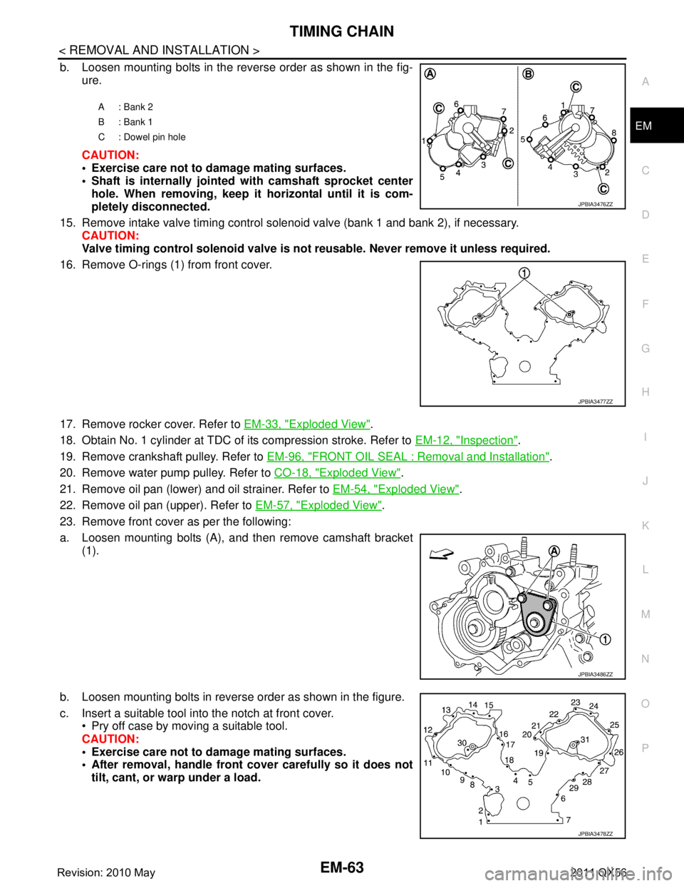
b. Loosen mounting bolts in the reverse order as shown in the fig-
ure.
CAUTION:
Exercise care not to damage mating surfaces.
Shaft is internally jointed with camshaft sprocket center
hole. When removing, keep it horizontal until it is com-
pletely disconnected.
15. Remove intake valve timing control solenoid valve (bank 1 and bank 2), if necessary. CAUTION:
Valve timing control solenoid valve is no t reusable. Never remove it unless required.
16. Remove O-rings (1) from front cover.
17. Remove rocker cover. Refer to EM-33, "
Exploded View".
18. Obtain No. 1 cylinder at TDC of its compression stroke. Refer to EM-12, "
Inspection".
19. Remove crankshaft pulley. Refer to EM-96, "
FRONT OIL SEAL : Removal and Installation".
20. Remove water pump pulley. Refer to CO-18, "
Exploded View".
21. Remove oil pan (lower) and oil strainer. Refer to EM-54, "
Exploded View".
22. Remove oil pan (upper). Refer to EM-57, "
Exploded View".
23. Remove front cover as per the following:
a. Loosen mounting bolts (A), and then remove camshaft bracket (1).
b. Loosen mounting bolts in reverse order as shown in the figure.
c. Insert a suitable tool into the notch at front cover. Pry off case by moving a suitable tool.
CAUTION:
Exercise care not to damage mating surfaces.
After removal, handle front cover carefully so it does not
tilt, cant, or warp under a load.
A: Bank 2
B: Bank 1
C : Dowel pin hole
JPBIA3476ZZ
JPBIA3477ZZ
JPBIA3486ZZ
JPBIA3478ZZ
Revision: 2010 May2011 QX56
Page 2626 of 5598
EM-64
< REMOVAL AND INSTALLATION >
TIMING CHAIN
24. Remove oil pump and oil pump drive spacer.
25. Remove front oil seal from front cover using suitable tool. Use screwdriver for removal.
CAUTION:
Be careful not to damage front cover.
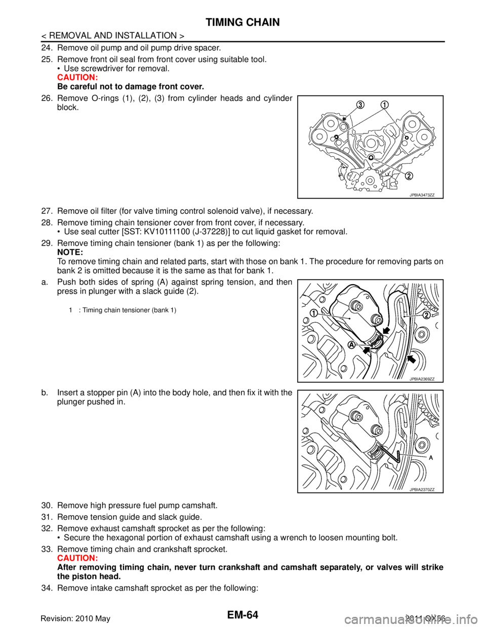
26. Remove O-rings (1), (2), (3) from cylinder heads and cylinder block.
27. Remove oil filter (for valve timing control solenoid valve), if necessary.
28. Remove timing chain tensioner cover from front cover, if necessary. Use seal cutter [SST: KV10111100 (J-37228)] to cut liquid gasket for removal.
29. Remove timing chain tensioner (bank 1) as per the following: NOTE:
To remove timing chain and related parts, start with those on bank 1. The procedure for removing parts on
bank 2 is omitted because it is the same as that for bank 1.
a. Push both sides of spring (A) against spring tension, and then press in plunger with a slack guide (2).
b. Insert a stopper pin (A) into the body hole, and then fix it with the
plunger pushed in.
30. Remove high pressure fuel pump camshaft.
31. Remove tension guide and slack guide.
32. Remove exhaust camshaft sprocket as per the following: Secure the hexagonal portion of exhaust camshaf t using a wrench to loosen mounting bolt.
33. Remove timing chain and crankshaft sprocket. CAUTION:
After removing timing chain, never turn cranksh aft and camshaft separately, or valves will strike
the piston head.
34. Remove intake camshaft sprocket as per the following:
JPBIA3473ZZ
1 : Timing chain tensioner (bank 1)
JPBIA2369ZZ
JPBIA2370ZZ
Revision: 2010 May2011 QX56