2011 INFINITI QX56 transmission
[x] Cancel search: transmissionPage 159 of 5598

AV
COMPONENT PARTSAV-11
< SYSTEM DESCRIPTION >
C
DE
F
G H
I
J
K L
M B A
O P
Video distributor It receives the image signal and sound signal from the AV control unit and then
transmits it to the headrest display unit.
It receives the image signal and sound signal from the auxiliary input jacks and then transmits it to the headrest display unit.
Switches image and sound output to headrest display unit, inputting image switch
signal from headrest display unit via hard wire.
Front auxiliary input jacks Image signal and sound signal of auxiliary input is transmitted to AV control unit.
Rear auxiliary input jacks
(Mobile entertainment system) Image signal and sound signal of auxiliary input is transmitted to video distributor.
BOSE amp. Inputs sound signal from AV control unit, and outputs sound signal to each speaker.
Front door speaker Outputs sound signal from BOSE amp.
Outputs high, mid and low range sounds.
Rear door speaker Outputs sound signal from BOSE amp.
Outputs high, mid and low range sounds.
Squawker Outputs sound signal from BOSE amp.
Outputs high and mid range sounds.
Rear door tweeter Outputs sound signal from BOSE amp.
Outputs high range sounds.
Roof speaker Outputs sound signal from BOSE amp.
Outputs high and mid range sounds.
Center speaker Outputs sound signal from BOSE amp.
Outputs high and mid range sounds.
Woofer Outputs sound signal from BOSE amp.
Outputs low range sounds.
Multifunction switch Operation panel is equipped with the centralized switch where audio, auxiliary in-
put and navigation, etc. operations are integrated.
Connected with preset switch via hardwire and operation signal is transmitted to AV control unit via AV communication.
Preset switch Operation panel is equipped with the centralized switch where audio and air con-
ditioner, etc. operations are integrated.
Connected with multifunction switch via hardwire, and operation signal is transmit- ted to AV control unit via AV communication.
The disk ejection operating signal is performed by hardwire.
Steering switch Operations for audio, hands-free phone and navigation, etc. are possible.
Steering switch signal (operation signal) is output to AV control unit.
Around view monitor control unit It supplies power to front camera, rear camera, and side camera. And then it su-
perimposes the images from each camera and outputs them to front display unit.
Superimpose the guiding line, predicted course line and sonar indicator to the
camera image that outputs to front display unit.
It performs the reception/transmission of communication signal with each camera.
It transmits the sonar operation signal from sonar control unit and receives the so- nar information from sonar control unit via AV communication.
It transmits the information received/transmitted with sonar control unit via AV communication to AV control unit.
Front camera It inputs the power supply from around view monitor control unit and outputs the
image of the vehicle front to around view monitor control unit.
It performs the reception/transmission of the communication signal with around view monitor control unit.
Rear camera It inputs the power supply from around view monitor control unit and outputs the
image of the vehicle rear to around view monitor control unit.
It performs the reception/transmission of the communication signal with around view monitor control unit.
Side camera LH It inputs the power supply from around view monitor control unit and outputs the
image of the vehicle LH to around view monitor control unit.
It performs the reception/transmission of the communication signal with around view monitor control unit.
Part name Description
Revision: 2010 May2011 QX56
Page 160 of 5598

AV-12
< SYSTEM DESCRIPTION >
COMPONENT PARTS
*1: Image signals cannot be received from iPod®.
Side camera RH It inputs the power supply from around view monitor control unit and outputs the
image of the vehicle RH to around view monitor control unit.
It performs the reception/transmission of the communication signal with around view monitor control unit.
Infrared LED
(Auxiliary lighting) It illuminates around the front RH wheel by the power supply from around view
monitor control unit to improve nighttime visibility of front-side view.
The infrared LED is an invisible light ray.
Sonar control unit It is connected with around view monitor control unit via AV communication and
receives the sonar operation signal from around view monitor control unit.
It transmits the sonar detection status to around view monitor control unit via AV
communication.
It judges the warning level according to the signal from corner sensor.
Corner sensor The obstacle distance is detected. The signal is transmitted to sonar control unit.
Steering angle sensor It is connected to the AV control unit and transmits the steering angle sensor signal
via CAN communication.
Microphone Used for hands-free phone operation.
Microphone signal is transmitted to AV control unit.
Power (Microphone VCC) is supplied from AV control unit.
GPS antenna GPS signal is received and transmitted to AV control unit.
Satellite radio antenna Receives the satellite radio waves and outputs it to AV control unit.
Antenna amp. Radio signal received by glass antenna (main) is amplified and transmitted to AV
control unit.
Power (antenna amp. ON signal) is supplied from AV control unit.
USB connector Image signal
*1 and sound signal of USB input is transmitted to AV control unit.
Part name Description
Revision: 2010 May2011 QX56
Page 266 of 5598

AV-118
< DTC/CIRCUIT DIAGNOSIS >
U1000 CAN COMM CIRCUIT
DTC/CIRCUIT DIAGNOSIS
U1000 CAN COMM CIRCUIT
DescriptionINFOID:0000000006216248
CAN (Controller Area Network) is a serial communication line for real-time application. It is an on-vehicle mul-
tiplex communication line with high data communication s peed and excellent error detection ability. Many elec-
tronic control units are equipped onto a vehicle, and each control unit shares information and links with other
control units during operation (not independently). In CA N communication, control units are connected with 2
communication lines (CAN-H, CAN-L) allowing a high rate of information transmission with less wiring. Each
control unit transmits/receives data but selectively reads required data only.
CAN Communication Signal Chart. Refer to LAN-28, "
CAN COMMUNICATION SYSTEM : CAN Communica-
tion Signal Chart".
DTC LogicINFOID:0000000006216249
DTC DETECTION LOGIC
Diagnosis ProcedureINFOID:0000000006216250
1.PERFORM SELF-DIAGNOSTIC
1. Turn ignition switch ON and wait for 2 seconds or more.
2. Check “Self Diagnostic Result” of “MULTI AV”.
Is
“CAN COMM CIRCUIT” displayed?
YES >> Refer to LAN-18, "Trouble Diagnosis Procedure".
NO >> Refer to GI-40, "
Intermittent Incident".
DTCDisplay contents of CON-
SULT-III DTC detection condition Probable malfunction location
U1000 CAN COMM CIRCUIT
[U1000] AV control unit is not transmitting or receiving
CAN communication signal for 2 seconds or
more.
CAN communication system.
Revision: 2010 May2011 QX56
Page 329 of 5598
AV
FRONT CAMERA COMMUNICATION SIGNAL CIRCUITAV-181
< DTC/CIRCUIT DIAGNOSIS >
C
DE
F
G H
I
J
K L
M B A
O P
FRONT CAMERA COMMUNICATION SIGNAL CIRCUIT
DescriptionINFOID:0000000006216350
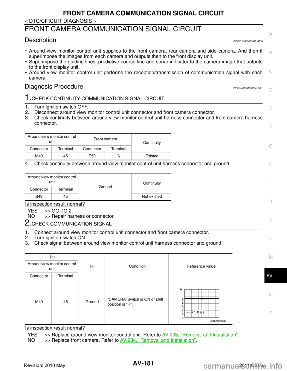
Around view monitor control unit supplies to the front camera, rear camera and side camera. And then it
superimpose the images from each camera and outputs then to the front display unit.
Superimpose the guiding lines, predictive course line and sonar indicator to the camera image that outputs
to the front display unit.
Around view monitor control unit performs the rec eption/transmission of communication signal with each
camera.
Diagnosis ProcedureINFOID:0000000006216351
1.CHECK CONTINUITY COMMUNI CATION SIGNAL CIRCUIT
1. Turn ignition switch OFF.
2. Disconnect around view monitor control unit connector and front camera connector.
3. Check continuity between around view monitor c ontrol unit harness connector and front camera harness
connector.
4. Check continuity between around view monitor control unit harness connector and ground.
Is inspection result normal?
YES >> GO TO 2.
NO >> Repair harness or connector.
2.CHECK COMMUNICATION SIGNAL
1. Connect around view monitor control uni t connector and front camera connector.
2. Turn ignition switch ON.
3. Check signal between around view monitor control unit harness connector and ground.
Is inspection result normal?
YES >> Replace around view monitor control unit. Refer to AV-233, "Removal and Installation".
NO >> Replace front camera. Refer to AV-234, "
Removal and Installation".
Around view monitor control
unit Front camera
Continuity
Connector Terminal Connector Terminal
M49 45 E50 6 Existed
Around view monitor control unit GroundContinuity
Connector Terminal
B49 45 Not existed
(+)
(− ) Condition Reference value
Around view monitor control
unit
Connector Terminal
M49 45 Ground “CAMERA” switch is ON or shift
position is “R”.
JSNIA0836GB
Revision: 2010 May2011 QX56
Page 330 of 5598
AV-182
< DTC/CIRCUIT DIAGNOSIS >
FRONT CAMERA IMAGE SIGNAL CIRCUIT
FRONT CAMERA IMAGE SIGNAL CIRCUIT
DescriptionINFOID:0000000006216352
Around view monitor control unit supplies to the front camera, rear camera and side came\
ra. And then itsuperimpose the images from each camera and outputs then to the front display unit.
Superimpose the guiding lines, predictive course line and sonar indicator to the camera image that outputs
to the front display unit.
Around view monitor control unit performs the rec eption/transmission of communication signal with each
camera.
Diagnosis ProcedureINFOID:0000000006216353
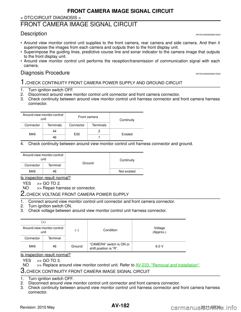
1.CHECK CONTINUITY FRONT CAMERA POWER SUPPLY AND GROUND CIRCUIT
1. Turn ignition switch OFF.
2. Disconnect around view monitor control unit connector and front camera connector.
3. Check continuity between around view monitor c ontrol unit harness connector and front camera harness
connector.
4. Check continuity between around view m onitor control unit harness connector and ground.
Is inspection result normal?
YES >> GO TO 2.
NO >> Repair harness or connector.
2.CHECK VOLTAGE FRONT CAMERA POWER SUPPLY
1. Connect around view monitor control unit connector and front camera connector.
2. Turn ignition switch ON.
3. Check voltage between around view m onitor control unit harness connector.
Is inspection result normal?
YES >> GO TO 3.
NO >> Replace around view monitor control unit. Refer to AV-233, "
Removal and Installation".
3.CHECK CONTINUITY FRONT CAMERA IMAGE SIGNAL CIRCUIT
1. Turn ignition switch OFF.
2. Disconnect around view monitor control unit connector and front camera connector.
3. Check continuity between around view monitor c ontrol unit harness connector and front camera harness
connector.
Around view monitor control
unit Front camera
Continuity
Connector Terminals Connector Terminals
M49 44
E50 2
Existed
46 1
Around view monitor control unit GroundContinuity
Connector Terminal
M49 46 Not existed
(+)
(− ) Condition Vo l ta g e
(Approx.)
Around view monitor control
unit
Connector Terminal
M49 46 Ground “CAMERA” switch is ON or
shift position is “R”.
6.0 V
Revision: 2010 May2011 QX56
Page 332 of 5598
AV-184
< DTC/CIRCUIT DIAGNOSIS >
REAR CAMERA COMMUNICATION SIGNAL CIRCUIT
REAR CAMERA COMMUNICATION SIGNAL CIRCUIT
DescriptionINFOID:0000000006216354
Around view monitor control unit supplies to the front camera, rear camera and side came\
ra. And then it
superimpose the images from each camera and outputs then to the front display unit.
Superimpose the guiding lines, predictive course line and sonar indicator to the camera image that outputs
to the front display unit.
Around view monitor control unit performs the rec eption/transmission of communication signal with each
camera.
Diagnosis ProcedureINFOID:0000000006216355
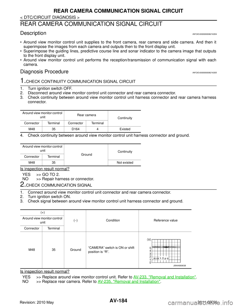
1.CHECK CONTINUITY COMMUNI CATION SIGNAL CIRCUIT
1. Turn ignition switch OFF.
2. Disconnect around view monitor control un it connector and rear camera connector.
3. Check continuity between around view monitor control unit harness connector and rear camera harness connector.
4. Check continuity between around view m onitor control unit harness connector and ground.
Is inspection result normal?
YES >> GO TO 2.
NO >> Repair harness or connector.
2.CHECK COMMUNICATION SIGNAL
1. Connect around view monitor control unit connector and rear camera connector.
2. Turn ignition switch ON.
3. Check signal between around view monitor control unit harness connector and ground.
Is inspection result normal?
YES >> Replace around view monitor control unit. Refer to AV-233, "Removal and Installation".
NO >> Replace rear camera. Refer to AV-235, "
Removal and Installation".
Around view monitor control
unit Rear camera
Continuity
Connector Terminal Connector Terminal
M48 35 D164 4 Existed
Around view monitor control unit GroundContinuity
Connector Terminal
M48 35 Not existed
(+)
(− ) Condition Reference value
Around view monitor control
unit
Connector Terminal
M48 35 Ground “CAMERA” switch is ON or shift
position is “R”.
JSNIA0836GB
Revision: 2010 May2011 QX56
Page 333 of 5598
AV
REAR CAMERA IMAGE SIGNAL CIRCUITAV-185
< DTC/CIRCUIT DIAGNOSIS >
C
DE
F
G H
I
J
K L
M B A
O P
REAR CAMERA IMAGE SIGNAL CIRCUIT
DescriptionINFOID:0000000006216356
Around view monitor control unit supplies to the front camera, rear camera and side camera. And then it
superimpose the images from each camera and outputs then to the front display unit.
Superimpose the guiding lines, predictive course line and sonar indicator to the camera image that outputs
to the front display unit.
Around view monitor control unit performs the rec eption/transmission of communication signal with each
camera.
Diagnosis ProcedureINFOID:0000000006216357
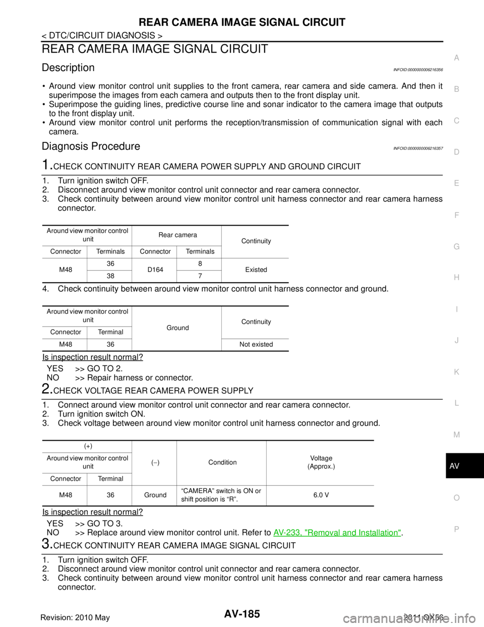
1.CHECK CONTINUITY REAR CAMERA POWER SUPPLY AND GROUND CIRCUIT
1. Turn ignition switch OFF.
2. Disconnect around view monitor control unit connector and rear camera connector.
3. Check continuity between around view monitor c ontrol unit harness connector and rear camera harness
connector.
4. Check continuity between around view monitor control unit harness connector and ground.
Is inspection result normal?
YES >> GO TO 2.
NO >> Repair harness or connector.
2.CHECK VOLTAGE REAR CAMERA POWER SUPPLY
1. Connect around view monitor control unit connector and rear camera connector.
2. Turn ignition switch ON.
3. Check voltage between around view monitor control unit harness connector and ground.
Is inspection result normal?
YES >> GO TO 3.
NO >> Replace around view monitor control unit. Refer to AV-233, "
Removal and Installation".
3.CHECK CONTINUITY REAR CAMERA IMAGE SIGNAL CIRCUIT
1. Turn ignition switch OFF.
2. Disconnect around view monitor control unit connector and rear camera connector.
3. Check continuity between around view monitor c ontrol unit harness connector and rear camera harness
connector.
Around view monitor control
unit Rear camera
Continuity
Connector Terminals Connector Terminals
M48 36
D164 8
Existed
38 7
Around view monitor control unit GroundContinuity
Connector Terminal
M48 36 Not existed
(+)
(− ) Condition Vo l ta g e
(Approx.)
Around view monitor control
unit
Connector Terminal
M48 36 Ground “CAMERA” switch is ON or
shift position is “R”.
6.0 V
Revision: 2010 May2011 QX56
Page 335 of 5598
AV
SIDE CAMERA LH COMMUNICATION SIGNAL CIRCUIT
AV-187
< DTC/CIRCUIT DIAGNOSIS >
C
D E
F
G H
I
J
K L
M B A
O P
SIDE CAMERA LH COMMUNI CATION SIGNAL CIRCUIT
DescriptionINFOID:0000000006216358
Around view monitor control unit supplies to the front camera, rear camera and side camera. And then it
superimpose the images from each camera and outputs then to the front display unit.
Superimpose the guiding lines, predictive course line and sonar indicator to the camera image that outputs
to the front display unit.
Around view monitor control unit performs the rec eption/transmission of communication signal with each
camera.
Diagnosis ProcedureINFOID:0000000006216359
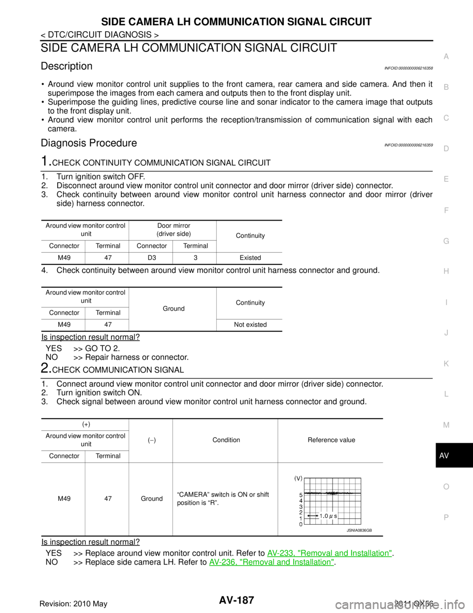
1.CHECK CONTINUITY COMMUNI CATION SIGNAL CIRCUIT
1. Turn ignition switch OFF.
2. Disconnect around view monitor control unit connector and door mirror (driver side) connector.
3. Check continuity between around view monitor control unit harness connector and door mirror (driver side) harness connector.
4. Check continuity between around view monitor control unit harness connector and ground.
Is inspection result normal?
YES >> GO TO 2.
NO >> Repair harness or connector.
2.CHECK COMMUNICATION SIGNAL
1. Connect around view monitor control unit c onnector and door mirror (driver side) connector.
2. Turn ignition switch ON.
3. Check signal between around view monitor control unit harness connector and ground.
Is inspection result normal?
YES >> Replace around view monitor control unit. Refer to AV-233, "Removal and Installation".
NO >> Replace side camera LH. Refer to AV-236, "
Removal and Installation".
Around view monitor control
unit Door mirror
(driver side) Continuity
Connector Terminal Connector Terminal
M49 47 D3 3 Existed
Around view monitor control unit GroundContinuity
Connector Terminal
M49 47 Not existed
(+)
(− ) Condition Reference value
Around view monitor control
unit
Connector Terminal
M49 47 Ground “CAMERA” switch is ON or shift
position is “R”.
JSNIA0836GB
Revision: 2010 May2011 QX56