Page 4216 of 5598

RF-2
Exploded View ........................................................32
Removal and Installation ........................................33
Adjustment ..............................................................33
SUNROOF MOTOR ASSEMBLY ......................35
Exploded View ..................................................... ...35
Removal and Installation ........................................36
SUNROOF UNIT ASSEMBLY ...........................37
Exploded View ..................................................... ...37
Removal and Installation ...................................... ...38
Disassembly and Assembly ....................................39
SUNSHADE .......................................................40
Exploded View ..................................................... ...40
Removal and Installation .........................................40
SUNROOF SWITCH ..........................................41
Removal and Installation ...................................... ...41
Revision: 2010 May2011 QX56
Page 4219 of 5598
COMPONENT PARTSRF-5
< SYSTEM DESCRIPTION >
C
DE
F
G H
I
J
L
M A
B
RF
N
O P
SYSTEM DESCRIPTION
COMPONENT PARTS
Component Parts LocationINFOID:0000000006141222
Component DescriptionINFOID:0000000006141223
JMKIA5171ZZ
1. Front door switch 2. BCM Refer to BCS-4, "
BODY CONTROL
SYSTEM : Compon ent Parts Loca-
tion". 3. Combination meter
Refer to MWI-6, "
METER SYSTEM :
Component Parts Location".
4. Sunroof motor assembly 5. Sunroof switch
Component Function
BCM Supplies the power supply to sunroof motor assembly.
Sunroof switch Transmits tilt up/down & slides open/close operation signal to sunroof motor assembly.
Sunroof motor assembly It is sunroof motor and CPU integrated type that enables tilt up/down & slide open/close by sun-
roof switch operation
Front door switch Detects door open/close condition and transmits to BCM.
Combination meter Transmits vehicle speed signal to sunroof motor assembly.
Revision: 2010 May2011 QX56
Page 4220 of 5598

RF-6
< SYSTEM DESCRIPTION >
SYSTEM
SYSTEM
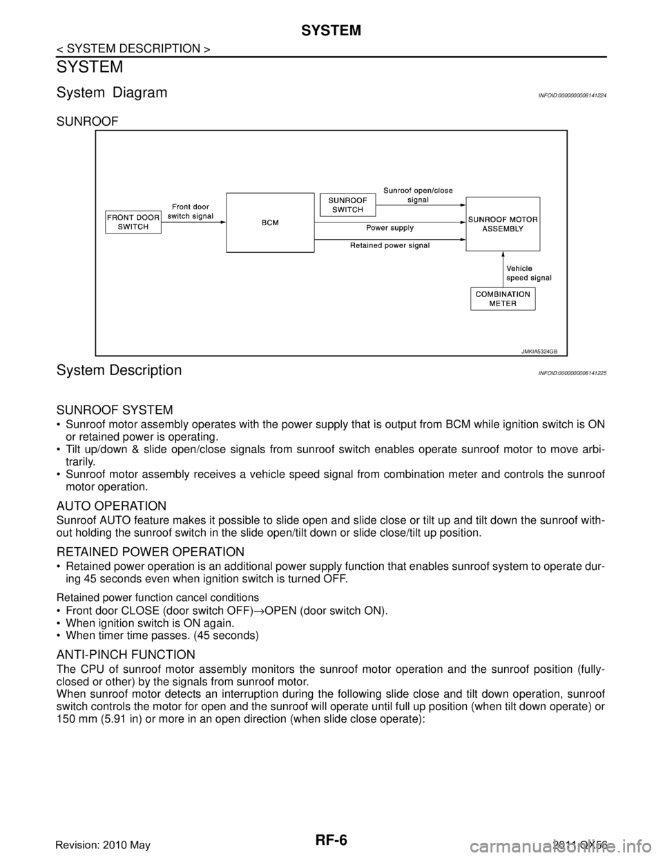
System DiagramINFOID:0000000006141224
SUNROOF
System DescriptionINFOID:0000000006141225
SUNROOF SYSTEM
Sunroof motor assembly operates with the power supply that is output from BCM while ignition switch is ON
or retained power is operating.
Tilt up/down & slide open/close signals from sunroof s witch enables operate sunroof motor to move arbi-
trarily.
Sunroof motor assembly receives a vehicle speed signal from combination meter and controls the sunroof motor operation.
AUTO OPERATION
Sunroof AUTO feature makes it possible to slide open and slide close or tilt up and tilt down the sunroof with-
out holding the sunroof switch in the slide open/tilt down or slide close/tilt up position.
RETAINED POWER OPERATION
Retained power operation is an additional power supply function that enables sunroof system to operate dur-
ing 45 seconds even when ignition switch is turned OFF.
Retained power function cancel conditions
Front door CLOSE (door switch OFF) →OPEN (door switch ON).
When ignition switch is ON again.
When timer time passes. (45 seconds)
ANTI-PINCH FUNCTION
The CPU of sunroof motor assembly monitors the s unroof motor operation and the sunroof position (fully-
closed or other) by the signals from sunroof motor.
When sunroof motor detects an interruption during the following slide close and tilt down operation, sunroof
switch controls the motor for open and the sunroof will operate until full up position (when tilt down operate) or
150 mm (5.91 in) or more in an open direction (when slide close operate):
JMKIA5324GB
Revision: 2010 May2011 QX56
Page 4222 of 5598
RF-8
< ECU DIAGNOSIS INFORMATION >
SUNROOF SYSTEM
SUNROOF SYSTEM
Reference ValueINFOID:0000000006141227
TERMINAL LAYOUT
PHYSICAL VALUES
JMKIA2225ZZ
Te r m i n a l N o .(Wire color) Description
ConditionVoltage (V)
(Approx.)
+ – Signal name Input/
Output
1
(B) Ground Ground — — 0
3
(Y) Ground Retained power signal Input Ignition switch ON
12
Within 45 seconds after ignition
switch is turned to OFF
When driver side or passenger side
door is opened during retained pow-
er operation 0
5
(P) Ground Sunroof open signal Input Sunroof switch in following position
TILT DOWN
SLIDE OPEN
0
Ignition switch ON 12
6
(W) Ground Sunroof power supply Input — 12
8
(SB) Ground Vehicle speed signal (2-
pulse)
InputSpeedometer operated [When vehi-
cle speed is approx.40km/ h
(25MPH)]
10
(GR) Ground Sunroof close signal Input Sunroof switch in following position
TILT UP
SLIDE CLOSE
0
Ignition switch ON 12
ELF1080D
Revision: 2010 May2011 QX56
Page 4223 of 5598
SUNROOF MOTOR ASSEMBLYRF-9
< WIRING DIAGRAM >
C
DE
F
G H
I
J
L
M A
B
RF
N
O P
WIRING DIAGRAM
SUNROOF MOTOR ASSEMBLY
Wiring DiagramINFOID:0000000006141228
JCKWM4481GB
Revision: 2010 May2011 QX56
Page 4224 of 5598
RF-10
< WIRING DIAGRAM >
SUNROOF MOTOR ASSEMBLY
JCKWM4482GB
Revision: 2010 May2011 QX56
Page 4225 of 5598
SUNROOF MOTOR ASSEMBLYRF-11
< WIRING DIAGRAM >
C
DE
F
G H
I
J
L
M A
B
RF
N
O P
JCKWM4483GB
Revision: 2010 May2011 QX56
Page 4226 of 5598
RF-12
< WIRING DIAGRAM >
SUNROOF MOTOR ASSEMBLY
JCKWM4484GB
Revision: 2010 May2011 QX56