2011 INFINITI QX56 oil filter
[x] Cancel search: oil filterPage 2631 of 5598
TIMING CHAINEM-69
< REMOVAL AND INSTALLATION >
C
DE
F
G H
I
J
K L
M A
EM
NP
O
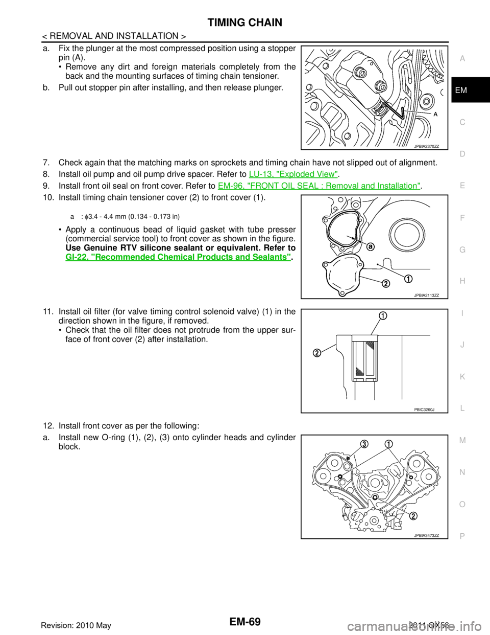
a. Fix the plunger at the most compressed position using a stopper
pin (A).
Remove any dirt and foreign materials completely from theback and the mounting surfaces of timing chain tensioner.
b. Pull out stopper pin after installing, and then release plunger.
7. Check again that the matching marks on sprockets and timing chain have not slipped out of alignment.
8. Install oil pump and oil pump drive spacer. Refer to LU-13, "
Exploded View".
9. Install front oil seal on front cover. Refer to EM-96, "
FRONT OIL SEAL : Removal and Installation".
10. Install timing chain tensioner cover (2) to front cover (1).
Apply a continuous bead of liquid gasket with tube presser(commercial service tool) to front cover as shown in the figure.
Use Genuine RTV silicone seal ant or equivalent. Refer to
GI-22, "
Recommended Chemical Products and Sealants".
11. Install oil filter (for valve timing control solenoid valve) (1) in the direction shown in the figure, if removed.
Check that the oil filter does not protrude from the upper sur-
face of front cover (2) after installation.
12. Install front cover as per the following:
a. Install new O-ring (1), (2), (3) onto cylinder heads and cylinder block.
JPBIA2370ZZ
a: φ3.4 - 4.4 mm (0.134 - 0.173 in)
JPBIA2113ZZ
PBIC3260J
JPBIA3473ZZ
Revision: 2010 May2011 QX56
Page 2647 of 5598
CAMSHAFTEM-85
< REMOVAL AND INSTALLATION >
C
DE
F
G H
I
J
K L
M A
EM
NP
O
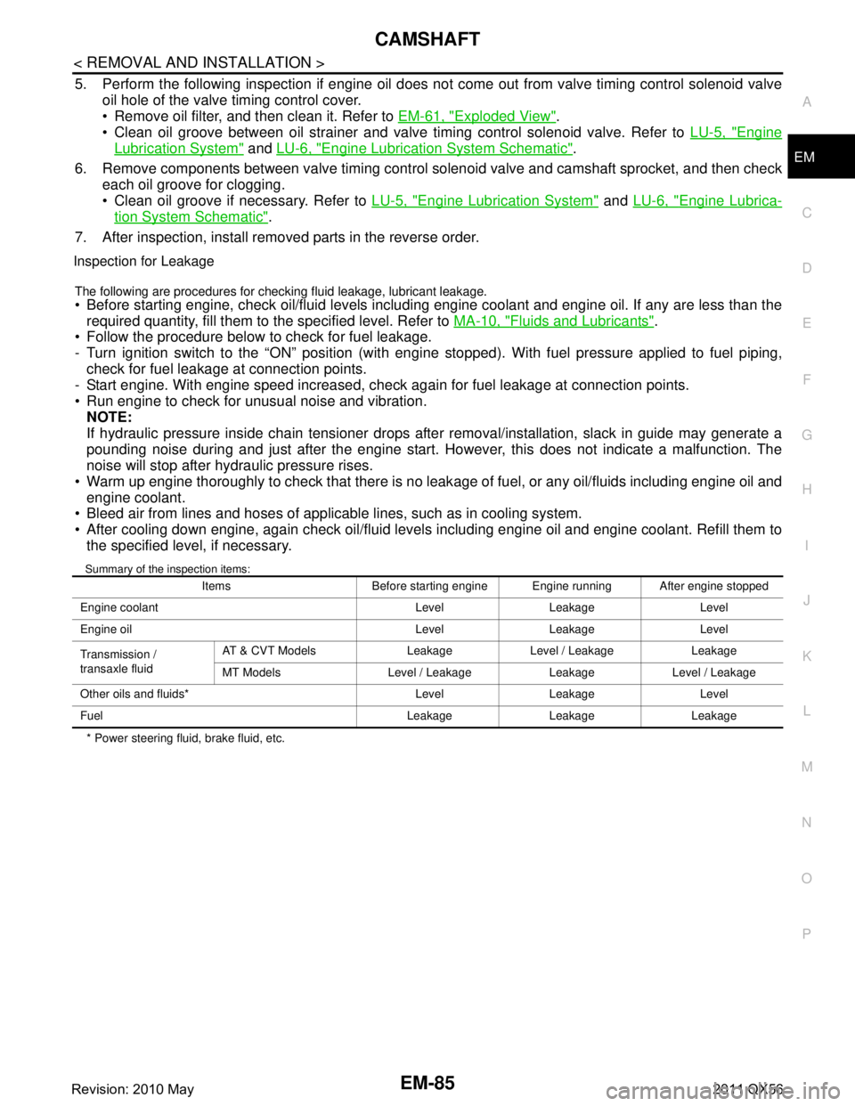
5. Perform the following inspection if engine oil does not
come out from valve timing control solenoid valve
oil hole of the valve timing control cover.
Remove oil filter, and then clean it. Refer to EM-61, "
Exploded View".
Clean oil groove between oil strainer and valve timing control solenoid valve. Refer to LU-5, "
Engine
Lubrication System" and LU-6, "Engine Lubrication System Schematic".
6. Remove components between valve timing control solenoid valve and camshaft sprocket, and then check each oil groove for clogging.
Clean oil groove if necessary. Refer to LU-5, "
Engine Lubrication System" and LU-6, "Engine Lubrica-
tion System Schematic".
7. After inspection, install removed parts in the reverse order.
Inspection for Leakage
The following are procedures for chec king fluid leakage, lubricant leakage.
Before starting engine, check oil/fluid levels including engine coolant and engine oil. If any are less than the
required quantity, fill them to the specified level. Refer to MA-10, "
Fluids and Lubricants".
Follow the procedure below to check for fuel leakage.
- Turn ignition switch to the “ON” position (with engi ne stopped). With fuel pressure applied to fuel piping,
check for fuel leakage at connection points.
- Start engine. With engine speed increased, check again for fuel leakage at connection points.
Run engine to check for unusual noise and vibration. NOTE:
If hydraulic pressure inside chain tensioner drops after removal/installation, slack in guide may generate a
pounding noise during and just after the engine start. However, this does not indicate a malfunction. The
noise will stop after hydraulic pressure rises.
Warm up engine thoroughly to check that there is no leak age of fuel, or any oil/fluids including engine oil and
engine coolant.
Bleed air from lines and hoses of applicable lines, such as in cooling system.
After cooling down engine, again check oil/fluid levels including engine oil and engine coolant. Refill them to
the specified level, if necessary.
Summary of the inspection items:
* Power steering fluid, brake fluid, etc. Items Before starting engine Engine running After engine stopped
Engine coolant Level Leakage Level
Engine oil Level Leakage Level
Transmission /
transaxle fluid AT & CVT Models Leakage Level / Leakage Leakage
MT Models Level / Leakage Leakage Level / Leakage
Other oils and fluids* Level Leakage Level
Fuel Leakage Leakage Leakage
Revision: 2010 May2011 QX56
Page 2648 of 5598
EM-86
< REMOVAL AND INSTALLATION >
CYLINDER HEAD
CYLINDER HEAD
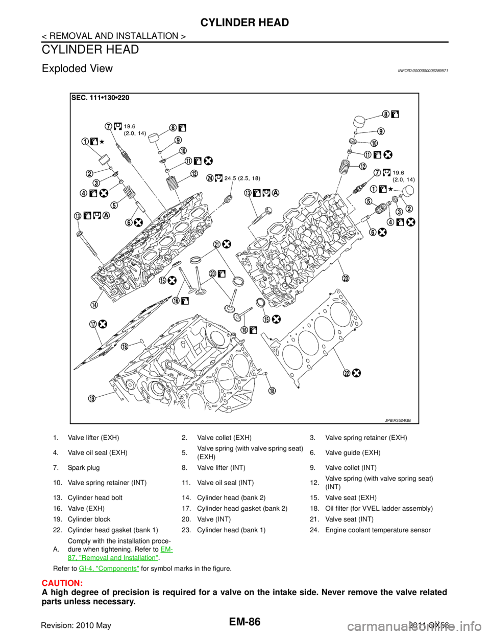
Exploded ViewINFOID:0000000006289571
CAUTION:
A high degree of precision is required for a valve on the intake side. Never remove the valve related
parts unless necessary.
1. Valve lifter (EXH) 2. Valve collet (EXH) 3. Valve spring retainer (EXH)
4. Valve oil seal (EXH) 5. Valve spring (with valve spring seat)
(EXH)6. Valve guide (EXH)
7. Spark plug 8. Valve lifter (INT) 9. Valve collet (INT)
10. Valve spring retainer (INT) 11. Valve oil seal (INT) 12. Valve spring (with valve spring seat)
(INT)
13. Cylinder head bolt 14. Cylinder head (bank 2) 15. Valve seat (EXH)
16. Valve (EXH) 17. Cylinder head gasket (bank 2) 18. Oil filter (for VVEL ladder assembly)
19. Cylinder block 20. Valve (INT) 21. Valve seat (INT)
22. Cylinder head gasket (bank 1) 23. Cylinder head (bank 1) 24. Engine coolant temperature sensor
A. Comply with the installation proce-
dure when tightening. Refer to
EM-
87, "Removal and Installation".
Refer to GI-4, "
Components" for symbol marks in the figure.
JPBIA3524GB
Revision: 2010 May2011 QX56
Page 2649 of 5598
CYLINDER HEADEM-87
< REMOVAL AND INSTALLATION >
C
DE
F
G H
I
J
K L
M A
EM
NP
O
NOTE:
As for replacement of parts on the intake side as
shown in the exploded view, replace VVEL ladder assem-
bly & cylinder head assembly. (Only valve oil seals are replaceable as a single part.)
VVEL ladder assembly cannot be replaced as a singl e part, because it is machined together with cylinder
head assembly.
Removal and InstallationINFOID:0000000006289572
REMOVAL
1. Remove the following parts: Rocker cover and spark plug: Refer to EM-33, "
Exploded View".
Intake manifold: Refer to EM-30, "
Exploded View".
Exhaust manifold: Refer to EM-40, "
Exploded View".
Water inlet and thermostat housing: Refer to CO-20, "
Exploded View".
Water pipe and heater pipe: Refer to CO-20, "
Exploded View".
Timing chain: Refer to EM-61, "
Exploded View".
Camshaft (EXH) and VVEL ladder assembly: Refer to EM-74, "
Exploded View".
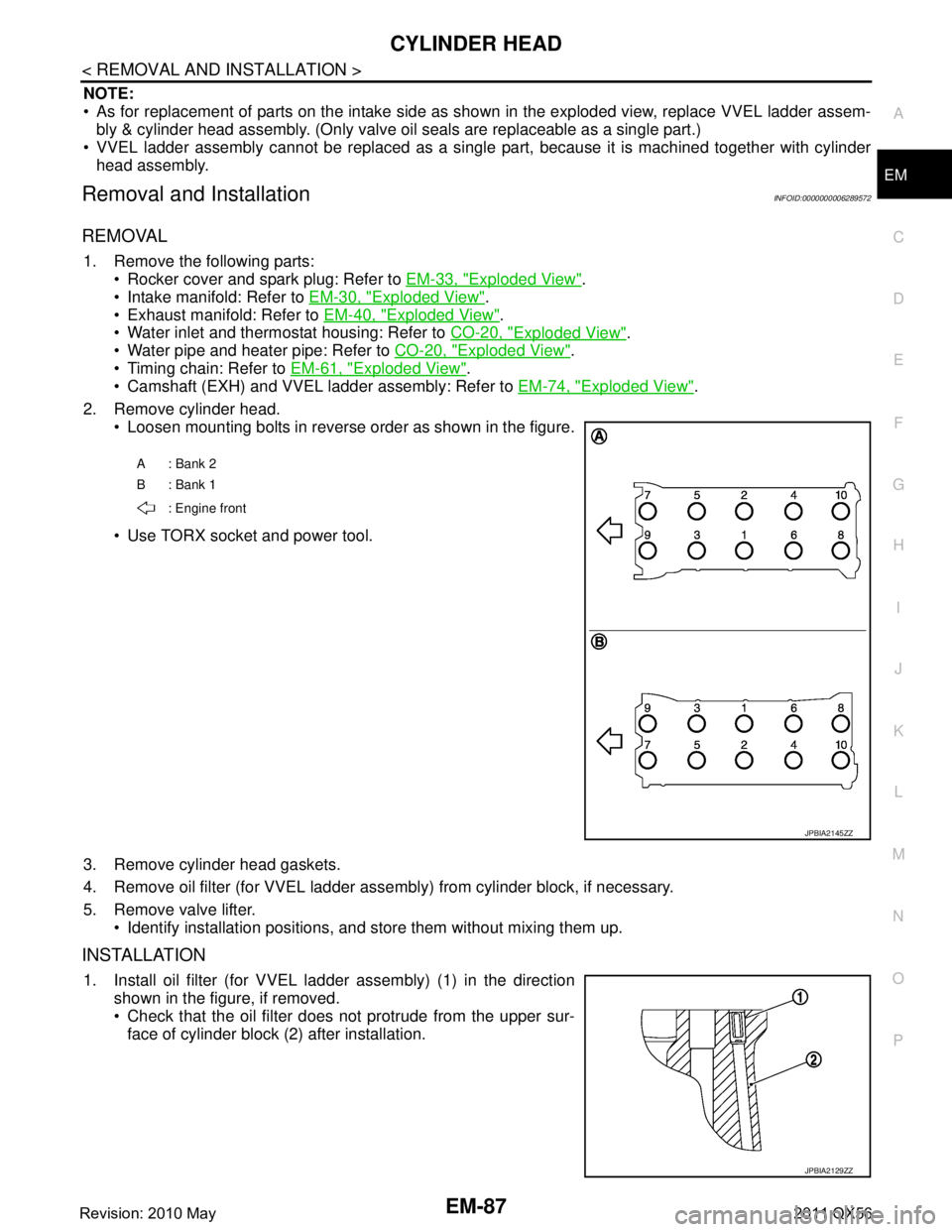
2. Remove cylinder head. Loosen mounting bolts in reverse order as shown in the figure.
Use TORX socket and power tool.
3. Remove cylinder head gaskets.
4. Remove oil filter (for VVEL ladder asse mbly) from cylinder block, if necessary.
5. Remove valve lifter. Identify installation positions, and store them without mixing them up.
INSTALLATION
1. Install oil filter (for VVEL l adder assembly) (1) in the direction
shown in the figure, if removed.
Check that the oil filter does not protrude from the upper sur-
face of cylinder block (2) after installation.
A: Bank 2
B: Bank 1
: Engine front
JPBIA2145ZZ
JPBIA2129ZZ
Revision: 2010 May2011 QX56
Page 2669 of 5598
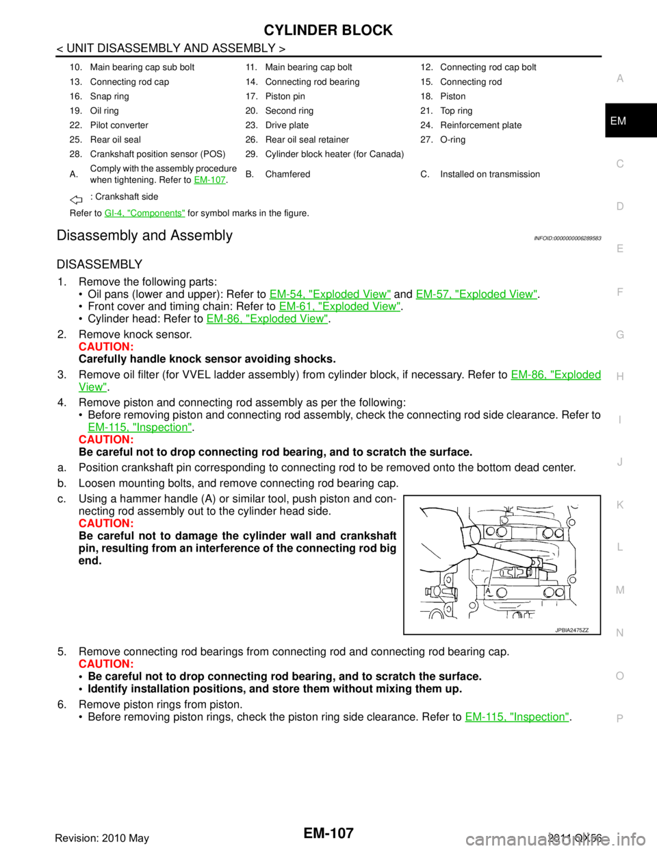
CYLINDER BLOCKEM-107
< UNIT DISASSEMBLY AND ASSEMBLY >
C
DE
F
G H
I
J
K L
M A
EM
NP
O
Disassembly and AssemblyINFOID:0000000006289583
DISASSEMBLY
1. Remove the following parts:
Oil pans (lower and upper): Refer to EM-54, "
Exploded View" and EM-57, "Exploded View".
Front cover and timing chain: Refer to EM-61, "
Exploded View".
Cylinder head: Refer to EM-86, "
Exploded View".
2. Remove knock sensor. CAUTION:
Carefully handle knock sensor avoiding shocks.
3. Remove oil filter (for VVEL ladder assembly ) from cylinder block, if necessary. Refer to EM-86, "
Exploded
View".
4. Remove piston and connecting rod assembly as per the following: Before removing piston and connecting rod assembly, check the connecting rod side clearance. Refer to
EM-115, "
Inspection".
CAUTION:
Be careful not to drop connecting r od bearing, and to scratch the surface.
a. Position crankshaft pin corresponding to connecting rod to be removed onto the bottom dead center.
b. Loosen mounting bolts, and remove connecting rod bearing cap.
c. Using a hammer handle (A) or similar tool, push piston and con- necting rod assembly out to the cylinder head side.
CAUTION:
Be careful not to damage the cylinder wall and crankshaft
pin, resulting from an interf erence of the connecting rod big
end.
5. Remove connecting rod bearings from connecting rod and connecting rod bearing cap.
CAUTION:
Be careful not to drop connecting rod bearing, and to scratch the surface.
Identify installation positions, and store them without mixing them up.
6. Remove piston rings from piston. Before removing piston rings, check the piston ring side clearance. Refer to EM-115, "
Inspection".
10. Main bearing cap sub bolt 11. Main bearing cap bolt 12. Connecting rod cap bolt
13. Connecting rod cap 14. Connecting rod bearing 15. Connecting rod
16. Snap ring 17. Piston pin 18. Piston
19. Oil ring 20. Second ring 21. Top ring
22. Pilot converter 23. Drive plate 24. Reinforcement plate
25. Rear oil seal 26. Rear oil seal retainer 27. O-ring
28. Crankshaft position sensor (POS) 29. Cylinder block heater (for Canada)
A.Comply with the assembly procedure
when tightening. Refer to
EM-107
.B. Chamfered C. Installed on transmission
: Crankshaft side
Refer to GI-4, "
Components" for symbol marks in the figure.
JPBIA2475ZZ
Revision: 2010 May2011 QX56
Page 2677 of 5598
![INFINITI QX56 2011 Factory Service Manual
CYLINDER BLOCKEM-115
< UNIT DISASSEMBLY AND ASSEMBLY >
C
DE
F
G H
I
J
K L
M A
EM
NP
O
f. Tighten connecting rod bolts. (clockwise)
CAUTION:
Always use the angle wrench [SST: KV10112100 (B T8653-A)]. INFINITI QX56 2011 Factory Service Manual
CYLINDER BLOCKEM-115
< UNIT DISASSEMBLY AND ASSEMBLY >
C
DE
F
G H
I
J
K L
M A
EM
NP
O
f. Tighten connecting rod bolts. (clockwise)
CAUTION:
Always use the angle wrench [SST: KV10112100 (B T8653-A)].](/manual-img/42/57033/w960_57033-2676.png)
CYLINDER BLOCKEM-115
< UNIT DISASSEMBLY AND ASSEMBLY >
C
DE
F
G H
I
J
K L
M A
EM
NP
O
f. Tighten connecting rod bolts. (clockwise)
CAUTION:
Always use the angle wrench [SST: KV10112100 (B T8653-A)]. Never make judgment by visual
inspection.
After tightening connecting rod bolts, c heck that crankshaft rotates smoothly.
Check the connecting rod side clearance. Refer to EM-115, "
Inspection".
16. Install knock sensors (1). Install knock sensors in the direction shown in the figure.
After installing knock sens or, connect harness connector, and
lay it out to front of the engine.
CAUTION:
Never tighten mounting bolts while holding connector.
If any impact by dropping is applied to knock sensor,
replace it with new one.
NOTE:
Check that there is no foreign material on the cylinder block
mating surface and the back surface of knock sensor.
Check that knock sensor does not interfere with other parts.
17. Install oil filter (for VVEL ladder assembly).
18. Install drive plate. Install drive plate (4) and reinforcement plate (3) as shown inthe figure.
When installing drive plate to crankshaft (1), be sure to cor- rectly align crankshaft side dowel pin and drive plate side
dowel pin hole.
CAUTION:
If these are not aligned correct ly, engine runs roughly and
“MIL” illuminates.
Holding ring gear with the ring gear stopper [SST: KV10119200 (J-49277)].
Tighten the mounting bolts crosswise over several times.
19. Assemble in the reverse order of disassembly.
InspectionINFOID:0000000006289584
CRANKSHAFT END PLAY
Measure the clearance between thrust bearings and crankshaft arm when crankshaft is moved fully forward or backward with a dial
indicator (A).
If the measured value exceeds t he limit, replace thrust bearings,
and measure again. If it still exceeds the limit, replace crankshaft
also. : 19.6 N·m (2.0 kg-m, 14.5 ft-lb)
Angle tightening: 90 degrees
: Engine front
2 : Pilot converter
A : Rounded : Engine front
JPBIA4515ZZ
JPBIA2275ZZ
Standard and limit : Refer to EM-137, "CylinderBlock".
JPBIA2477ZZ
Revision: 2010 May2011 QX56
Page 2995 of 5598
PRECAUTIONSGI-31
< PRECAUTION >
C
DE
F
G H
I
J
K L
M B
GI
N
O P
Dispose of used oil and used oil filters through authorized waste disposal contractors to licensed waste dis-
posal sites, or to the waste oil reclamation trade. If in doubt, contact the local authority for advice on disposal
facilities.
It is illegal to pour used oil on to the ground, dow n sewers or drains, or into water sources.
The regulations concerning po llution vary between regions.
Air ConditioningINFOID:0000000006280875
Use an approved refrigerant recovery unit any time t he air conditioning system must be discharged. Refer to
HA section “REFRIGERANT” fo r specific instructions.
FuelINFOID:0000000006280876
INFINITI recommends the use of unleaded premium gasoli ne with an octane rating of at least 91 AKI (Anti-
Knock Index) number (Research octane number 96).
If unleaded premium gasoline is not available, unleaded r egular gasoline with an octane rating of at least 87
AKI number (Research octane number 91), can be used. In such case, engine performance may be decrease.
CAUTION:
Using a fuel other than that specified could ad versely affect the emission control system, and may
also affect warranty coverage.
Under no circumstances should a leaded gasoline be used, because this will damage the three-way
catalyst.
Do not use E-85 fuel in the vehicle . The vehicle is not designed to run on E-85 fuel. Using E-85 fuel
can damage the fuel system components and is not covered by the INFINITI vehicle limited warranty.
Revision: 2010 May2011 QX56
Page 3654 of 5598
LU-1
ENGINE
C
DE
F
G H
I
J
K L
M
SECTION LU
A
LU
N
O P
CONTENTS
ENGINE LUBRICATION SYSTEM
PRECAUTION ................ ...............................2
PRECAUTIONS .............................................. .....2
Liquid Gasket ..................................................... ......2
PREPARATION ............................................3
PREPARATION .............................................. .....3
Special Service Tool ........................................... ......3
Commercial Service Tool ..........................................3
SYSTEM DESCRIPTION ..............................5
LUBRICATION SYSTEM ............................... .....5
Engine Lubrication System ................................. ......5
Engine Lubrication System Schematic ......................6
PERIODIC MAINTENANCE ..........................7
ENGINE OIL ................................................... .....7
Inspection ............................................................ ......7
Draining .....................................................................8
Refilling .....................................................................8
OIL FILTER .........................................................9
Removal and Installation ..................................... ......9
Inspection ............................................................ .....9
REMOVAL AND INSTALLATION ...............11
OIL COOLER ....................................................11
Exploded View ..................................................... ....11
Removal and Installation .........................................11
Inspection ................................................................12
OIL PUMP .........................................................13
Exploded View .........................................................13
Removal and Installation .........................................13
Disassembly and Assembly .....................................14
Inspection ................................................................14
SERVICE DATA AND SPECIFICATIONS
(SDS) ............... .............................................
17
SERVICE DATA AND SPECIFICATIONS
(SDS) .................................................................
17
Periodical Maintenance Specification .................. ....17
Engine Oil Pressure ...............................................17
Oil Pump .................................................................17
Regulator Valve ......................................................17
Revision: 2010 May2011 QX56