2011 INFINITI QX56 oil filter
[x] Cancel search: oil filterPage 3688 of 5598
MA-18
< PERIODIC MAINTENANCE >
ENGINE MAINTENANCE
3. Warm up the engine and check area around drain plug and oil filter for engine oil leakage.
4. Stop the engine and wait for 10 minutes.
5. Check the engine oil level. Refer to LU-7, "
Inspection".
OIL FILTER
OIL FILTER : Removal and InstallationINFOID:0000000006394843
REMOVAL
1. Remove front under cover.
2. Drain engine oil. Refer to MA-17, "
ENGINE OIL : Draining".
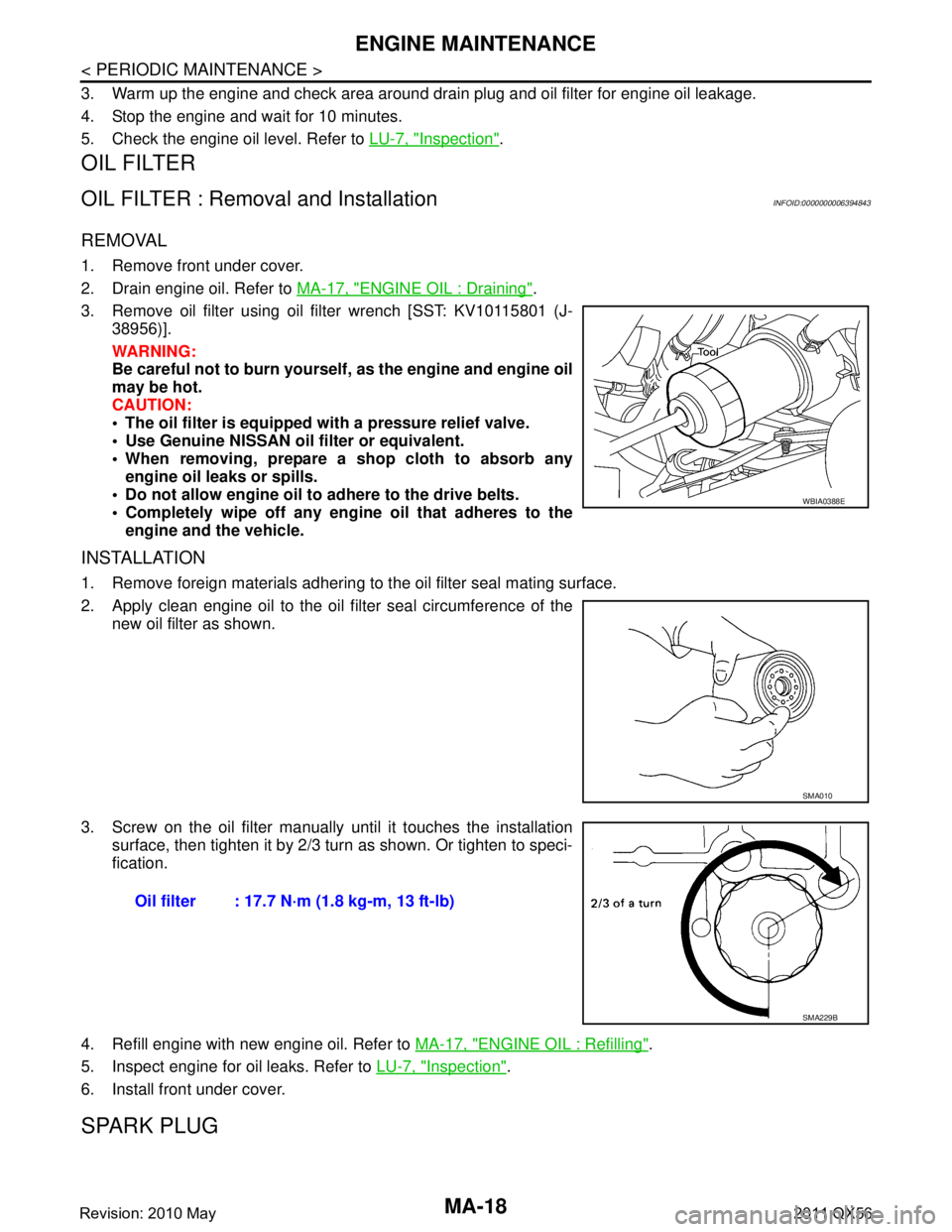
3. Remove oil filter using oil filter wrench [SST: KV10115801 (J- 38956)].
WARNING:
Be careful not to burn yourself, as the engine and engine oil
may be hot.
CAUTION:
The oil filter is equipped with a pressure relief valve.
Use Genuine NISSAN oil filter or equivalent.
When removing, prepare a sh op cloth to absorb any
engine oil leaks or spills.
Do not allow engine oil to adhere to the drive belts.
Completely wipe off any engi ne oil that adheres to the
engine and the vehicle.
INSTALLATION
1. Remove foreign materials adhering to the oil filter seal mating surface.
2. Apply clean engine oil to the oil f ilter seal circumference of the
new oil filter as shown.
3. Screw on the oil filter manually until it touches the installation
surface, then tighten it by 2/3 turn as shown. Or tighten to speci-
fication.
4. Refill engine with new engine oil. Refer to MA-17, "
ENGINE OIL : Refilling".
5. Inspect engine for oil leaks. Refer to LU-7, "
Inspection".
6. Install front under cover.
SPARK PLUG
WBIA0388E
SMA010
Oil filter : 17.7 N·m (1.8 kg-m, 13 ft-lb)
SMA229B
Revision: 2010 May2011 QX56
Page 3705 of 5598
SERVICE DATA AND SPECIFICATIONS (SDS)
MA-35
< SERVICE DATA AND SPECIFICATIONS (SDS)
C
D E
F
G H
I
J
K L
M B
MA
N
O A
SERVICE DATA AND SPECIFICATIONS (SDS)
SERVICE DATA AND SPECIFICATIONS (SDS)
DRIVE BELTS
DRIVE BELTS : Drive BeltsINFOID:0000000006394853
DRIVE BELT
ENGINE COOLANT
ENGINE COOLANT : Periodical Maintenance SpecificationINFOID:0000000006394856
ENGINE COOLANT CAPACITY (APPROXIMATELY)
Unit: (US qt, Imp qt)
ENGINE OIL
ENGINE OIL : Periodical Maintenance SpecificationINFOID:0000000006394855
ENGINE OIL CAPACITY (APPROXIMATE)
Unit: (US qt, Imp qt)
SPARK PLUG
SPARK PLUG : Spark PlugINFOID:0000000006394854
SPARK PLUG
Unit: mm (in)
ROAD WHEEL
ROAD WHEEL : Road WheelINFOID:0000000006349771
ALUMINUM WHEEL
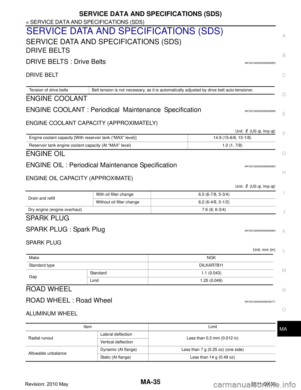
Tension of drive belts Belt tension is not necessary, as it is automatically adjusted by drive belt auto-tensioner.
Engine coolant capacity [With reservoir tank (“MAX” level)] 14.9 (15-6/8, 13-1/8)
Reservoir tank engine coolant capacity (At “MAX” level) 1.0 (1, 7/8)
Drain and refill
With oil filter change 6.5 (6-7/8, 5-3/4)
Without oil filter change 6.2 (6-4/8, 5-1/2)
Dry engine (engine overhaul) 7.6 (8, 6-3/4)
Make NGK
Standard type DILKAR7B11
Gap Standard 1.1 (0.043)
Limit 1.25 (0.049)
Item Limit
Radial runout Lateral deflection
Less than 0.3 mm (0.012 in)
Vertical deflection
Allowable unbalance Dynamic (At flange) Less than 7 g (0.25 oz) (one side)
Static (At flange) Less than 14 g (0.49 oz)
Revision: 2010 May2011 QX56
Page 3754 of 5598
MWI
SYSTEMMWI-11
< SYSTEM DESCRIPTION >
C
DE
F
G H
I
J
K L
M B A
O P
ARRANGEMENT OF COMBINATION METER
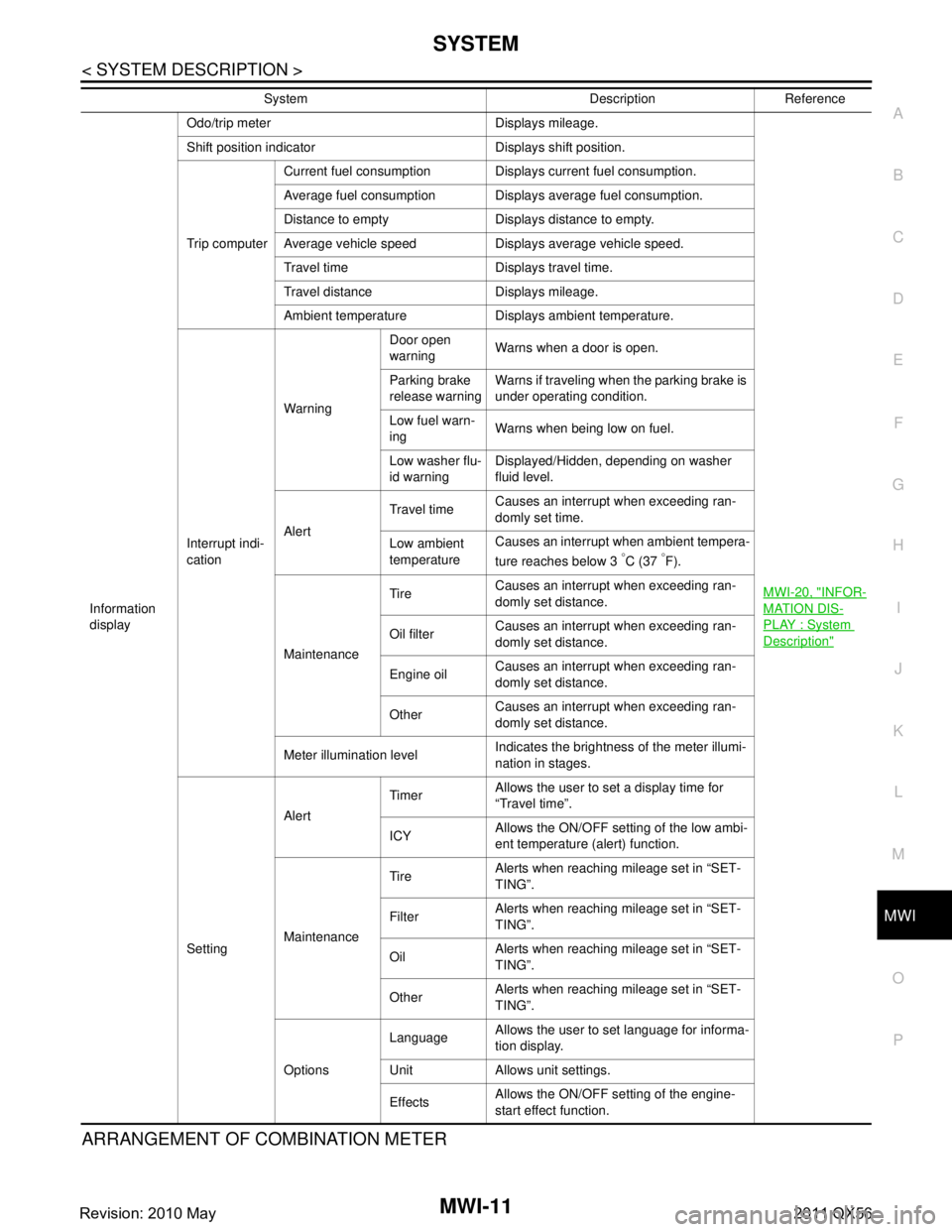
Information
display Odo/trip meter Displays mileage.
MWI-20, "
INFOR-
MATION DIS-
PLAY : System
Description"
Shift position indicator Displays shift position.
Trip computerCurrent fuel consumption Displays current fuel consumption.
Average fuel consumption Displays average fuel consumption.
Distance to empty Displays distance to empty.
Average vehicle speed Displays average vehicle speed.
Travel time Displays travel time.
Travel distance Displays mileage.
Ambient temperature Displays ambient temperature.
Interrupt indi-
cation Warning
Door open
warning
Warns when a door is open.
Parking brake
release warning Warns if traveling when the parking brake is
under operating condition.
Low fuel warn-
ing Warns when being low on fuel.
Low washer flu-
id warning Displayed/Hidden, depending on washer
fluid level.
Alert Travel time
Causes an interrupt when exceeding ran-
domly set time.
Low ambient
temperature Causes an interrupt when ambient tempera-
ture reaches below 3
°C (37 °F).
Maintenance Tire
Causes an interrupt when exceeding ran-
domly set distance.
Oil filter Causes an interrupt when exceeding ran-
domly set distance.
Engine oil Causes an interrupt when exceeding ran-
domly set distance.
Other Causes an interrupt when exceeding ran-
domly set distance.
Meter illumination level Indicates the brightness of the meter illumi-
nation in stages.
Setting Alert
Timer
Allows the user to set a display time for
“Travel time”.
ICY Allows the ON/OFF setting of the low ambi-
ent temperature (alert) function.
Maintenance Tire
Alerts when reaching mileage set in “SET-
TING”.
Filter Alerts when reaching mileage set in “SET-
TING”.
Oil Alerts when reaching mileage set in “SET-
TING”.
Other Alerts when reaching mileage set in “SET-
TING”.
Options Language
Allows the user to set language for informa-
tion display.
Unit Allows unit settings.
Effects Allows the ON/OFF setting of the engine-
start effect function.
System Description Reference
Revision: 2010 May2011 QX56
Page 3768 of 5598
MWI
SYSTEMMWI-25
< SYSTEM DESCRIPTION >
C
DE
F
G H
I
J
K L
M B A
O P
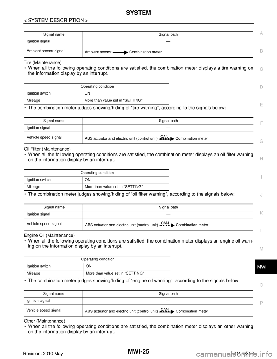
Tire (Maintenance) When all the following operating conditions are satisfied, the combination meter displays a tire warning on
the information display by an interrupt.
The combination meter judges showing/hiding of “tire warning”, according to the signals below:
Oil Filter (Maintenance)
When all the following operating conditions are satisfied, the combination meter displays an oil filter warning on the information display by an interrupt.
The combination meter judges showing/hiding of “oil filter warning”, according to the signals below:
Engine Oil (Maintenance)
When all the following operating conditions are satisfied, the combination meter displays an engine oil warn-
ing on the information display by an interrupt.
The combination meter judges showing/hiding of “engine oil warning”, according to the signals below:
Other (Maintenance)
When all the following operating conditions are satisfied, the combination meter displays an other warning on the information display by an interrupt.
Signal name Signal path
Ignition signal —
Ambient sensor signal Ambient sensor Combination meter
Operating condition
Ignition switch ON
Mileage More than value set in “SETTING”
Signal name Signal path
Ignition signal —
Vehicle speed signal ABS actuator and electric unit (control unit) Combination meter
Operating condition
Ignition switch ON
Mileage More than value set in “SETTING”
Signal name Signal path
Ignition signal —
Vehicle speed signal ABS actuator and electric unit (control unit) Combination meter
Operating condition
Ignition switch ON
Mileage More than value set in “SETTING”
Signal name Signal path
Ignition signal —
Vehicle speed signal ABS actuator and electric unit (control unit) Combination meter
Revision: 2010 May2011 QX56
Page 3769 of 5598
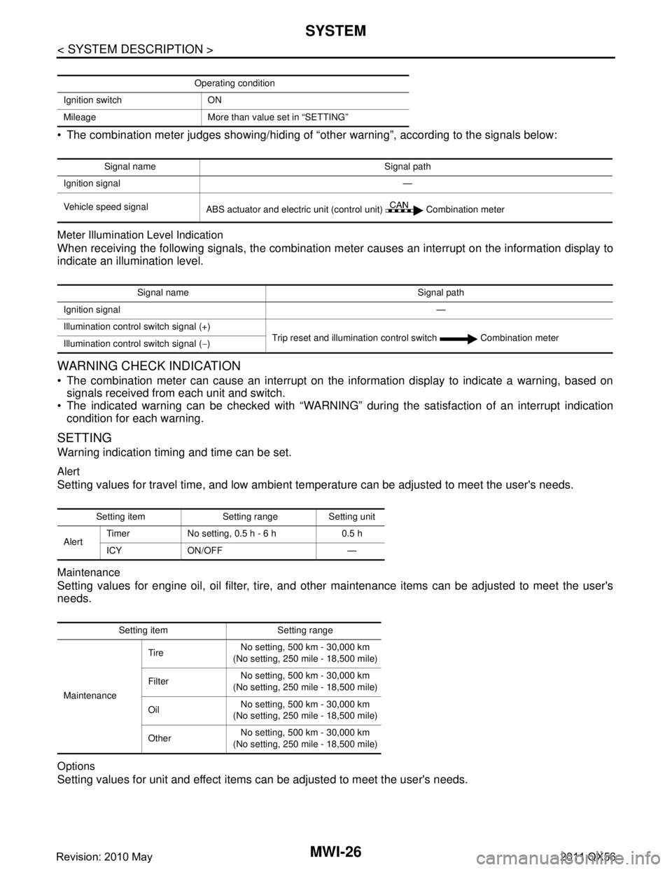
MWI-26
< SYSTEM DESCRIPTION >
SYSTEM
The combination meter judges showing/hiding of “other warning”, according to the signals below:
Meter Illumination Level Indication
When receiving the following signals, the combination meter causes an interrupt on the information display to
indicate an illumination level.
WARNING CHECK INDICATION
The combination meter can cause an interrupt on the information display to indicate a warning, based onsignals received from each unit and switch.
The indicated warning can be checked with “WARNING” during the satisfaction of an interrupt indication
condition for each warning.
SETTING
Warning indication timing and time can be set.
Alert
Setting values for travel time, and low ambient te mperature can be adjusted to meet the user's needs.
Maintenance
Setting values for engine oil, oil filter, tire, and other maintenance items can be adjusted to meet the user's
needs.
Options
Setting values for unit and effect items can be adjusted to meet the user's needs.
Operating condition
Ignition switch ON
Mileage More than value set in “SETTING”
Signal name Signal path
Ignition signal —
Vehicle speed signal ABS actuator and electric unit (control unit) Combination meter
Signal name Signal path
Ignition signal —
Illumination control switch signal (+) Trip reset and illumination control switch Combination meter
Illumination control switch signal ( −)
Setting item Setting range Setting unit
Alert Timer No setting, 0.5 h - 6 h 0.5 h
ICY ON/OFF —
Setting item Setting range
Maintenance Tire
No setting, 500 km - 30,000 km
(No setting, 250 mile - 18,500 mile)
Filter No setting, 500 km - 30,000 km
(No setting, 250 mile - 18,500 mile)
Oil No setting, 500 km - 30,000 km
(No setting, 250 mile - 18,500 mile)
Other No setting, 500 km - 30,000 km
(No setting, 250 mile - 18,500 mile)
Revision: 2010 May2011 QX56
Page 4398 of 5598
![INFINITI QX56 2011 Factory Service Manual
SCS-38
< REMOVAL AND INSTALLATION >[HBMC]
HYDRAULIC BODY-MOTION CONTROL SYSTEM
Completely engage hooks on frame when installing accumulator
assembly.
ACCUMULATOR : InspectionINFOID:0000000006256026 INFINITI QX56 2011 Factory Service Manual
SCS-38
< REMOVAL AND INSTALLATION >[HBMC]
HYDRAULIC BODY-MOTION CONTROL SYSTEM
Completely engage hooks on frame when installing accumulator
assembly.
ACCUMULATOR : InspectionINFOID:0000000006256026](/manual-img/42/57033/w960_57033-4397.png)
SCS-38
< REMOVAL AND INSTALLATION >[HBMC]
HYDRAULIC BODY-MOTION CONTROL SYSTEM
Completely engage hooks on frame when installing accumulator
assembly.
ACCUMULATOR : InspectionINFOID:0000000006256026
INSPECTION AFTER REMOVAL
O-ring must be free of scratches and damage.
Pipe and tube must be free of scratches and damage.
INSPECTION AFTER INSTALLATION
Check oil leakage, twists, deformation, cont act with other parts, and loose connections.
ADJUSTMENT AFTER INSTALLATION
Perform air bleeding. Refer to SCS-18, "Work Procedure".
ACCUMULATOR : DisposalINFOID:0000000006256027
CAUTION:
Always wear safety goggles.
Always wear safety gloves.
Be careful since pressure is higher when temperature is high.
Be careful since metal shavings or oi l may be blown away by compressed gas.
Discard drained oil in accordance with local laws and regulations.
WORK PROCEDURE
1. Remove both tanks using an oil filter wrench.
2. Secure tank using a vise.
3. Drill a hole as shown in the figure ( �z) using an electric drill.
Drain gas and oil.
NOTE:
Gas is colorless, odorless, and harmless.
Use an electric drill with a drill bit of approximately 4 mm (0.16 in).
Drilling a hole is easier when electric drill speed is slow.
PPMU, MIDDLE TUBE AS SEMBLY, PPMU PIPE
JSEIA0202ZZ
JSEIA0182ZZ
Revision: 2010 May2011 QX56
Page 4403 of 5598
![INFINITI QX56 2011 Factory Service Manual
HYDRAULIC BODY-MOTION CONTROL SYSTEMSCS-43
< REMOVAL AND INSTALLATION > [HBMC]
C
D
F
G H
I
J
K L
M A
B
SCS
N
O P
PPMU, MIDDLE TUBE ASSEMBLY, PPMU PIPE : InspectionINFOID:0000000006256030
INSPECTION A INFINITI QX56 2011 Factory Service Manual
HYDRAULIC BODY-MOTION CONTROL SYSTEMSCS-43
< REMOVAL AND INSTALLATION > [HBMC]
C
D
F
G H
I
J
K L
M A
B
SCS
N
O P
PPMU, MIDDLE TUBE ASSEMBLY, PPMU PIPE : InspectionINFOID:0000000006256030
INSPECTION A](/manual-img/42/57033/w960_57033-4402.png)
HYDRAULIC BODY-MOTION CONTROL SYSTEMSCS-43
< REMOVAL AND INSTALLATION > [HBMC]
C
D
F
G H
I
J
K L
M A
B
SCS
N
O P
PPMU, MIDDLE TUBE ASSEMBLY, PPMU PIPE : InspectionINFOID:0000000006256030
INSPECTION AFTER REMOVAL
O-ring must be free of scratches and damage.
Pipe and tube must be free of scratches and damage.
INSPECTION AFTER INSTALLATION
Check oil leakage, twists, deformation, contact with other parts, and loose connections.
ADJUSTMENT AFTER INSTALLATION
Perform air bleeding. Refer to SCS-18, "Work Procedure".
PPMU, MIDDLE TUBE ASSEMBLY , PPMU PIPE : DisposalINFOID:0000000006256031
CAUTION:
Always wear safety goggles.
Always wear safety gloves.
Be careful since pressure is higher when temperature is high.
Be careful since metal shavings or oi l may be blown away by compressed gas.
Discard drained oil in accordance wi th local laws and regulations.
WORK PROCEDURE
1. Remove both tanks using an oil filter wrench.
2. Secure tank using a vise.
3. Drill a hole as shown in the figure ( �z) using an electric drill.
Drain gas and oil.
NOTE:
Gas is colorless, odorless, and harmless.
Use an electric drill with a drill bit of approximately 4 mm (0.16
in).
Drilling a hole is easier when electric drill speed is slow.
REAR TUBE ASSEMBLY
JSEIA0182ZZ
Revision: 2010 May2011 QX56
Page 5186 of 5598
![INFINITI QX56 2011 Factory Service Manual
TM-98
< BASIC INSPECTION >[7AT: RE7R01B]
A/T FLUID COOLER
DIAGNOSIS PROCEDURE
NOTE:
Insufficient cleaning of the cooler inlet hose exte
rior may lead to inaccurate debris identification.
1. Position INFINITI QX56 2011 Factory Service Manual
TM-98
< BASIC INSPECTION >[7AT: RE7R01B]
A/T FLUID COOLER
DIAGNOSIS PROCEDURE
NOTE:
Insufficient cleaning of the cooler inlet hose exte
rior may lead to inaccurate debris identification.
1. Position](/manual-img/42/57033/w960_57033-5185.png)
TM-98
< BASIC INSPECTION >[7AT: RE7R01B]
A/T FLUID COOLER
DIAGNOSIS PROCEDURE
NOTE:
Insufficient cleaning of the cooler inlet hose exte
rior may lead to inaccurate debris identification.
1. Position an oil pan under the A/T inlet and outlet cooler hoses.
2. Clean the exterior and tip of the cooler inlet hose.
3. Insert the extension adapter hose of a can of Transmission
Cooler Cleaner (Nissan P/N 999MP-AM006) into the cooler out-
let hose.
CAUTION:
Wear safety glasses and rubber gloves when spraying the Transmission Cooler Cleaner.
Spray Transmission Cooler Cleaner only with adequate
ventilation.
Avoid contact with eyes and skin.
Never breath vapors or spray mist.
4. Hold the hose and can as high as possible and spray Transmis- sion Cooler Cleaner in a continuous stream into the cooler outlet
hose until ATF flows out of the cooler inlet hose for 5 seconds.
5. Tie a common white, basket-type coffee filter to the end of the cooler inlet hose.
6. Insert the tip of an air gun into the end of the cooler outlet hose.
7. Wrap a shop rag around the air gun tip and end of cooler outlet hose.
8. Blow compressed air regulated to 5 to 9 kg/cm
2 (71 to 128 psi)
through the cooler outlet hose to force any remaining ATF into
the coffee filter.
9. Remove the coffee filter from the end of the cooler inlet hose.
10. Perform “INSPECTION PROCEDURE”.
INSPECTION PROCEDURE
1. Inspect the coffee filter for debris.
a. If small metal debris less than 1 mm (0.040 in) in size or metal powder is found in the coffee filter, this is normal. If normal
debris is found, the A/T fluid cooler/radiator can be re-used and
the procedure is ended.
JPDIA0712GB
JPDIA0714GB
JPDIA0715GB
SCIA2967E
Revision: 2010 May2011 QX56