2011 INFINITI QX56 fuel pressure
[x] Cancel search: fuel pressurePage 3758 of 5598

MWI
SYSTEMMWI-15
< SYSTEM DESCRIPTION >
C
DE
F
G H
I
J
K L
M B A
O P
REFUEL CONTROL
The combination meter accelerates the fuel gauge if the all conditions listed below are met, or the ignition
switch is ON from OFF.
Ignition switch is ON position.
The vehicle is not moving.
The fuel level change by 15 (4 US gal, 3-1/4 Imp gal) or more.
ENGINE OIL PRESSURE GAUGE
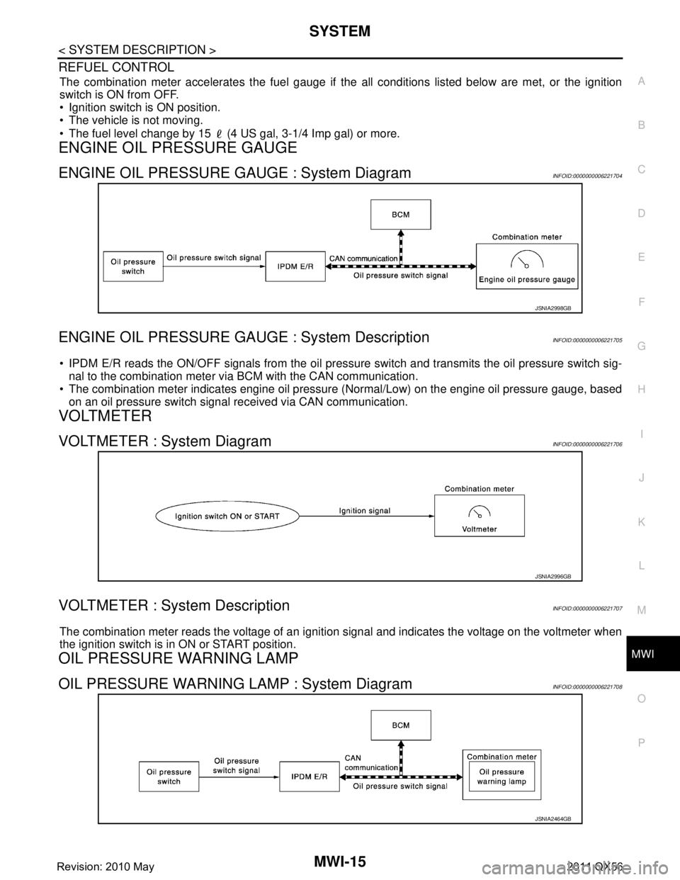
ENGINE OIL PRESSURE GAUGE : System DiagramINFOID:0000000006221704
ENGINE OIL PRESSURE GAUGE : System DescriptionINFOID:0000000006221705
IPDM E/R reads the ON/OFF signals from the oil pressure switch and transmits the oil pressure switch sig-
nal to the combination meter via BCM with the CAN communication.
The combination meter indicates engine oil pressure (Normal/Low) on the engine oil pressure gauge, based
on an oil pressure switch signal received via CAN communication.
VOLTMETER
VOLTMETER : System DiagramINFOID:0000000006221706
VOLTMETER : System DescriptionINFOID:0000000006221707
The combination meter reads the voltage of an ignition signal and indicates the voltage on the voltmeter when
the ignition switch is in ON or START position.
OIL PRESSURE WARNING LAMP
OIL PRESSURE WARNING LAMP : System DiagramINFOID:0000000006221708
JSNIA2998GB
JSNIA2996GB
JSNIA2464GB
Revision: 2010 May2011 QX56
Page 3759 of 5598

MWI-16
< SYSTEM DESCRIPTION >
SYSTEM
OIL PRESSURE WARNING LAMP : System Description
INFOID:0000000006221709
IPDM E/R reads the ON/OFF signals fr om the oil pressure switch and transmits the oil pressure switch sig-
nal to the combination meter via BCM with the CAN communication.
The combination meter turns the oil pressure warning lamp ON (at the time of a reduction in hydraulic pres-
sure)/OFF (except at the time of a reduction in hydraulic pressure) according to the oil pressure switch signal
received via CAN communication.
MASTER WARNING LAMP
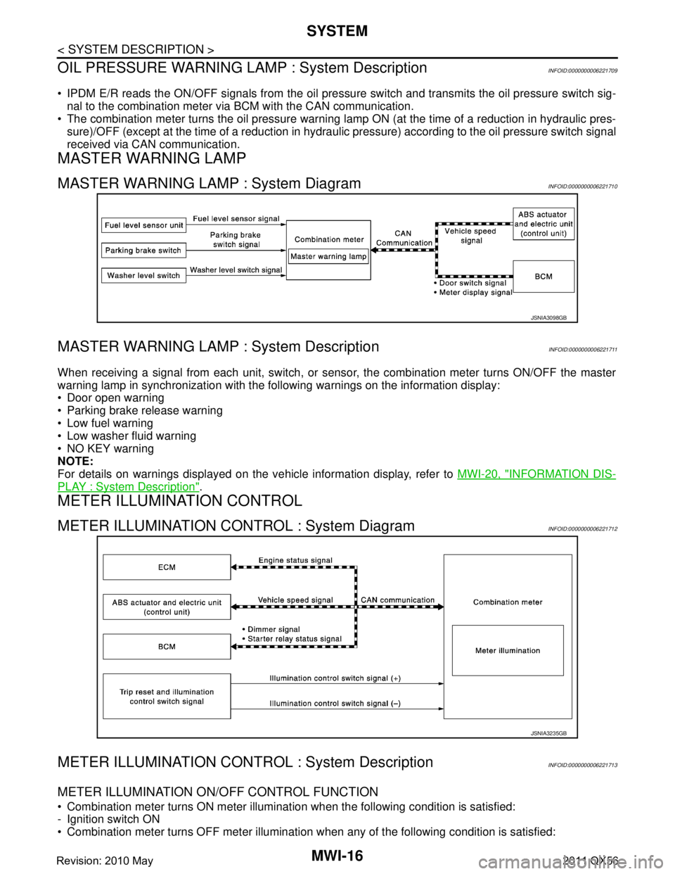
MASTER WARNING LAMP : System DiagramINFOID:0000000006221710
MASTER WARNING LAMP : System DescriptionINFOID:0000000006221711
When receiving a signal from each unit, switch, or s ensor, the combination meter turns ON/OFF the master
warning lamp in synchronization with the following warnings on the information display:
Door open warning
Parking brake release warning
Low fuel warning
Low washer fluid warning
NO KEY warning
NOTE:
For details on warnings displayed on the vehicle information display, refer to MWI-20, "
INFORMATION DIS-
PLAY : System Description".
METER ILLUMINATION CONTROL
METER ILLUMINATION CONTROL : System DiagramINFOID:0000000006221712
METER ILLUMINATION CONTRO L : System DescriptionINFOID:0000000006221713
METER ILLUMINATION ON/OFF CONTROL FUNCTION
Combination meter turns ON meter illumination when the following condition is satisfied:
- Ignition switch ON
Combination meter turns OFF meter illumination when any of the following condition is satisfied:
JSNIA3098GB
JSNIA3235GB
Revision: 2010 May2011 QX56
Page 3761 of 5598

MWI-18
< SYSTEM DESCRIPTION >
SYSTEM
When recognizing an engine start, the combination meter controls the following items for producing the effect.
Speedometer
Tachometer
Engine coolant temperature gauge
Fuel gauge
Engine oil pressure gauge
Voltmeter
Meter illumination
Meter and Illumination Operations During Engine-start Effect
The combination meter controls the following items during the engine-start effect.
NOTE:
The pointers are stopped and illumination is turned off while cranking the engine.
Engine Start Judgement
The combination meter judges “engine-start” and activates the engine-start effect only once when the follow-
ing operational conditions are all satisfied.
NOTE:
Engine-start effect exits when any of the above operat ional conditions is cancelled during the engine-start
effect.
Signal path
The combination meter judges “engine-start,” according to the following signals and activates the engine-start
effect function.
DRIVER WELCOME FUNCTION
Control item Operation
Speedometer Sweeps the pointer.
Tachometer Sweeps the pointer.
Engine coolant temperature gauge Stops the pointer.
Fuel gauge Stops the pointer.
Engine oil pressure gauge Stops the pointer.
Voltmeter Stops the pointer.
Meter illumination Pointers Turns on the illumination at the effect level.
Information display Turns on the illumination at the normal brightness level.
Other than those above Increases the brightness to the effect level in stages.
Condition
Ignition switch ON position
Vehicle speed Less than 1 km/h (0.6 MPH)
Engine state Other than the time of cranking the engine
500 rpm or more
Information display
(SETTING) The setting of “EFFECT” is “ON.”
Signal name Signal path
Ignition signal —
Starter relay status signal BCM Combination meter
Engine speed signal ECM Combination meter
Engine status signal
Vehicle speed signal ABS actuator and electric unit (control unit) Combination meter
Revision: 2010 May2011 QX56
Page 3772 of 5598

MWI
DIAGNOSIS SYSTEM (COMBINATION METER)
MWI-29
< SYSTEM DESCRIPTION >
C
D E
F
G H
I
J
K L
M B A
O P
DIAGNOSIS SYSTEM (COMBINATION METER)
On Board Diagnosis FunctionINFOID:0000000006221719
ON BOARD DIAGNOSIS ITEM
The combination meter allows the following diagnosis items with the on-board diagnosis function.
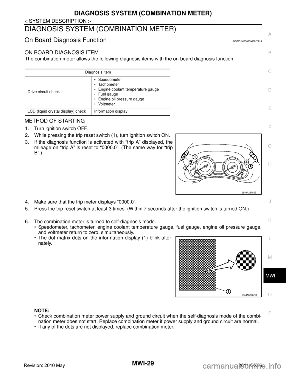
METHOD OF STARTING
1. Turn ignition switch OFF.
2. While pressing the trip reset switch (1), turn ignition switch ON.
3. If the diagnosis function is activated with “trip A” displayed, the
mileage on “trip A” is reset to “0000.0”. (The same way for “trip
B”.)
4. Make sure that the trip meter displays “0000.0”.
5. Press the trip reset switch at least 3 times. (Wit hin 7 seconds after the ignition switch is turned ON.)
6. The combination meter is turned to self-diagnosis mode. Speedometer, tachometer, engine coolant temper ature gauge, fuel gauge, engine oil pressure gauge,
and voltmeter return to zero, simultaneously.
The dot matrix dots on the information display (1) blink alter-
nately.
NOTE:
Check combination meter power supply and ground circuit when the self-diagnosis mode of the combi- nation meter does not start. Replace combination meter if power supply and ground circuit are normal.
If any of the dots are not displayed, replace combination meter.
Diagnosis item
Drive circuit check Speedometer
Tachometer
Engine coolant temperature gauge
Fuel gauge
Engine oil pressure gauge
Voltmeter
LCD (liquid crystal display) check Information display
JSNIA2978ZZ
JSNIA0020GB
Revision: 2010 May2011 QX56
Page 3774 of 5598
![INFINITI QX56 2011 Factory Service Manual
MWI
DIAGNOSIS SYSTEM (COMBINATION METER)
MWI-31
< SYSTEM DESCRIPTION >
C
D E
F
G H
I
J
K L
M B A
O P
W TEMP METER
[ ° C] XValue of engine coolant temperature signal is received from ECM via CAN com INFINITI QX56 2011 Factory Service Manual
MWI
DIAGNOSIS SYSTEM (COMBINATION METER)
MWI-31
< SYSTEM DESCRIPTION >
C
D E
F
G H
I
J
K L
M B A
O P
W TEMP METER
[ ° C] XValue of engine coolant temperature signal is received from ECM via CAN com](/manual-img/42/57033/w960_57033-3773.png)
MWI
DIAGNOSIS SYSTEM (COMBINATION METER)
MWI-31
< SYSTEM DESCRIPTION >
C
D E
F
G H
I
J
K L
M B A
O P
W TEMP METER
[ ° C] XValue of engine coolant temperature signal is received from ECM via CAN com-
munication.
NOTE:
215 is displayed when the malfunction signal is input.
ABS W/L
[On/Off] Status of ABS warning lamp detected fr
om ABS warning lamp signal is received
from ABS actuator and electric unit (control unit) via CAN communication.
VDC/TCS IND
[On/Off] Status of VDC OFF indicator lamp detected from VDC OFF indicator lamp signal
is received from ABS actuator
and electric unit (control unit) via CAN communica-
tion.
SLIP IND
[On/Off] Status of VDC warning lamp detected from VDC warning lamp signal received
from ABS actuator and electric unit (control unit) via CAN communication.
BRAKE W/L
[On/Off] Status of brake warning lamp detected from brake warning lamp signal is received
from ABS actuator and electric unit (control unit) via CAN communication.
NOTE:
Displays “Off” if the brake warning lamp is illuminated when the valve check starts,
the parking brake switch is turned ON or the brake fluid level switch is turned ON.
DOOR W/L
[On/Off] Status of door open warning detected from door switch signal received from BCM
via CAN communication.
HI-BEAM IND
[On/Off] Status of high beam indicator lamp detected from high beam request signal is re-
ceived from BCM via CAN communication.
TURN IND
[On/Off] Status of turn indicator lamp detected from turn indicator signal is received from
BCM via CAN communication.
FR FOG IND
[Off] This item is displayed, but cannot be monitored.
RR FOG IND
[Off] This item is displayed, but cannot be monitored.
LIGHT IND
[On/Off] Status of light indicator lamp detected from position light request signal is received
from BCM via CAN communication.
OIL W/L
[On/Off] Status of oil pressure warning lamp detected from oil pressure switch signal is re-
ceived from BCM via CAN communication.
MIL
[On/Off] Status of malfunction indicator lamp detected from malfunctioning indicator lamp
signal is received from ECM via CAN communication.
GLOW IND
[Off] This item is displayed, but cannot be monitored.
CRUISE IND
[On/Off] Status of CRUISE indicator detected from ASCD status signal is received from
ECM via CAN communicat ion. (ASCD models)
Status of CRUISE indicator de tected from meter display signal is received from
ADAS control unit via CAN communication. (ICC models)
SET IND
[On/Off] Status of SET indicator detected from meter display signal is received from ADAS
control unit via CAN communication.
CRUISE W/L
[On/Off] Status of CRUISE warning lamp
judged from ICC warning lamp signal received
from ADAS control unit with CAN communication line.
BA W/L
[On/Off] Status of IBA OFF indicator lamp judged from IBA OFF indicator lamp signal re-
ceived from ADAS control unit with CAN communication line.
ATC/T-AMT W/L
[On/Off] Status of A/T CHECK warning lamp judged
from A/T CHECK indicator lamp signal
received from TCM with CAN communication line.
ATF TEMP W/L
[Off] This item is displayed, but cannot be monitored.
4WD W/L
[On/Off] Status of 4WD warning lamp judged from 4WD warning lamp signal received from
4WD control unit with
CAN communication line.
FUEL W/L
[On/Off] Low-fuel warning lamp status detected by the identified fuel level.
WASHER W/L
[On/Off] Status of low washer fluid warning judged from washer level switch input to com-
bination meter.
Display item [Unit]
MAIN
SIGNALS Description
Revision: 2010 May2011 QX56
Page 3777 of 5598

MWI-34
< SYSTEM DESCRIPTION >
DIAGNOSIS SYSTEM (COMBINATION METER)
Display item Description
ABS W/L Lighting history of ABS warning lamp.
VDC/TCS IND Lighting history of VDC OFF indicator lamp.
SLIP IND Lighting history of VDC warning lamp.
BRAKE W/L Lighting history of brake warning lamp.
DOOR W/L Lighting history of door open warning.
TRUNK/GLAS-H This item is displa yed, but cannot be monitored.
OIL W/L Lighting history of oil pressure warning lamp.
C-ENG W/L Lighting history of malfunction indicator lamp.
C-ENG2 W/L This item is displayed, but cannot be monitored.
CRUISE IND Lighting history of CRUISE indicator lamp.
SET IND Lighting history of SET indicator lamp.
CRUISE W/L Lighting history of CRUISE warning lamp.
BA W/L Lighting history of IBA OFF indicator lamp.
O/D OFF IND This item is displayed, but cannot be monitored.
ATC/T-AMT W/L Lighting history of A/T CHECK warning lamp.
ATF TEMP W/L This item is displayed, but cannot be monitored.
CVT IND This item is displayed, but cannot be monitored.
SPORT IND This item is displayed, but cannot be monitored.
4WD W/L Lighting history of 4WD warning lamp.
FUEL W/L Lighting history of low fuel level warning.
WASHER W/L Lighting history of low washer fluid warning.
AIR PRES W/L Lighting history of low tire pressure warning lamp.
KEY G/Y W/L Lighting history of KEY warning lamp.
KEY R W/L This item is displaye d, but cannot be monitored.
KEY KNOB W/L This item is displa yed, but cannot be monitored.
EPS W/L This item is displayed, but cannot be monitored.
e-4WD This item is displayed, but cannot be monitored.
AFS OFF IND This item is displayed, but cannot be monitored.
4WAS/RAS W/L This item is displayed, but cannot be monitored.
HDC W/L This item is displayed, but cannot be monitored.
SYS FAIL W/L This item is displa yed, but cannot be monitored.
SFT POSI W/L This item is displayed, but cannot be monitored.
HV BAT W/L This item is displayed, but cannot be monitored.
HEV BRAKE W/L This item is displayed, but cannot be monitored.
SFT OPER W/L This item is displayed, but cannot be monitored.
LANE W/L Lighting history of lane departure warning lamp.
CHAGE W/L This item is displayed, but cannot be monitored.
OIL LEV LOW This item is displayed, but cannot be monitored.
DPF W/L This item is displayed, but cannot be monitored.
TRAILER IND This item is displayed, but cannot be monitored.
RUN FLAT W/L This item is displa yed, but cannot be monitored.
E-SUS W/L This item is displayed, but cannot be monitored.
LAUNCH CNT W/L This item is displayed, but cannot be monitored.
BRAKE PAD W/L This item is displa yed, but cannot be monitored.
Revision: 2010 May2011 QX56
Page 3779 of 5598

MWI-36
< ECU DIAGNOSIS INFORMATION >
COMBINATION METER
LIGHT INDIgnition switch
ONTail lamp indicator lamp ON On
Tail lamp indicator lamp OFF Off
OIL W/L Ignition switch
ONOil pressure warning lamp ON On
Oil pressure warning lamp OFF Off
MIL Ignition switch
ONMalfunction indicator lamp ON On
Malfunction indicator lamp OFF Off
GLOW IND Ignition switch
ONNOTE:
This item is displayed, but cannot be moni-
tored.
Off
CRUISE IND Ignition switch
ONCRUISE indicator ON On
CRUISE indicator OFF Off
SET IND Ignition switch
ONSET indicator ON On
SET indicator OFF Off
CRUISE W/L Ignition switch
ONCRUISE warning lamp ON On
CRUISE warning lamp OFF Off
BA W/L Ignition switch
ONIBA OFF indicator lamp ON On
IBA OFF indicator lamp OFF Off
ATC/T-AMT W/L Ignition switch
ONA/T check warning lamp ON On
A/T check warning lamp OFF Off
ATF TEMP W/L Ignition switch
ONNOTE:
This item is displayed, but cannot be moni-
tored.
Off
4WD W/L Ignition switch
ON4WD warning lamp ON On
4WD warning lamp OFF Off
FUEL W/L Ignition switch
ONDuring low fuel warning indication On
Other than the above Off
WASHER W/L Ignition switch
ONDuring low washer flui
d warning indication On
Other than the above Off
AIR PRES W/L Ignition switch
ONLow tire pressure
warning lamp ON On
Low tire pressure warning lamp OFF Off
KEY G/Y W/L Ignition switch
ONKEY warning lamp (Green/Yellow) ON On
KEY warning lamp (Green/Yellow) OFF Off
KEY KNOB W/L Ignition switch
ONNOTE:
This item is displayed, but cannot be moni-
tored.
Off
AFS OFF IND Ignition switch
ONAFS OFF indicator lamp ON On
AFS OFF indicator lamp OFF Off
DDS W/L Ignition switch
ONNOTE:
This item is displayed, but cannot be moni-
tored.
Off
LANE W/L
Ignition switch
ONLane departure warning lamp ON On
Lane departure warning lamp OFF Off
LDP IND Ignition switch
ONLDP ON indicator lamp ON On
LDP ON indicator lamp OFF Off
AT P W / L Ignition switch
ONATP warning lamp ON On
ATP warning lamp OFF Off
Monitor Item Condition Value/Status
Revision: 2010 May2011 QX56
Page 4261 of 5598

RSU-6
< PERIODIC MAINTENANCE >
WHEEL ALIGNMENT
WHEEL ALIGNMENT
InspectionINFOID:0000000006225661
DESCRIPTION
Measure wheel alignment under unladen conditions.
NOTE:
“Unladen conditions” means that fuel, engine coolant, and lubricant are full. Spare tire, jack, hand tools and
mats are in designated positions.
PRELIMINARY CHECK
Check the following:
Tires for improper air pressure and wear
Road wheels for runout. Refer to WT-64, "
Inspection".
Wheel bearing axial end play. Refer to RAX-5, "
Inspection".
Ball joint axial end play of suspension arm and front lower link. Refer to RSU-20, "
Ball Joint".
Shock absorber operation
Each mounting point of axle and suspension for looseness and deformation
Each of front lower link, rear lower link, rear suspension member, suspension arm and shock absorber for
cracks, deformation, and other damage
Vehicle height (posture)
GENERAL INFORMATION AND RECOMMENDATIONS
A four-wheel thrust alignment should be performed.
- This type of alignment is recomm ended for any NISSAN/INFINITI vehicle.
- The four-wheel “thrust” process helps ensure that t he vehicle is properly aligned and the steering wheel is
centered.
- The alignment rack itself should be capable of accepting any NISSAN/INFINITI vehicle.
- The rack should be checked to ensure that it is level.
Make sure the machine is properly calibrated.
- Your alignment equipment should be regularly calib rated in order to give correct information.
- Check with the manufacturer of your specific equi pment for their recommended Service/Calibration Sched-
ule.
ALIGNMENT PROCESS
IMPORTANT:
Use only the alignment specifications listed in this Service Manual.
When displaying the alignment settings, many alignment machines use “indicators”: (Green/red, plus or
minus, Go/No Go). Never use these indicators.
- The alignment specifications programmed into your machine that operate these indicators may not be cor-
rect.
- This may result in an ERROR.
Some newer alignment machines are equipped with an optional “Rolling Compensation” method to “com- pensate” the sensors (alignment targets or head units). Never use this “Rolling Compensation” method.
- Use the “Jacking Compensation Method”. After installi ng the alignment targets or head units, raise the vehi-
cle and rotate the wheels 1/2 turn both ways.
- See Instructions in the alignment machine you're using for more information on this.
AdjustmentINFOID:0000000006225662
CAMBER
Revision: 2010 May2011 QX56