2011 INFINITI QX56 fuel pressure
[x] Cancel search: fuel pressurePage 2993 of 5598
PRECAUTIONSGI-29
< PRECAUTION >
C
DE
F
G H
I
J
K L
M B
GI
N
O P
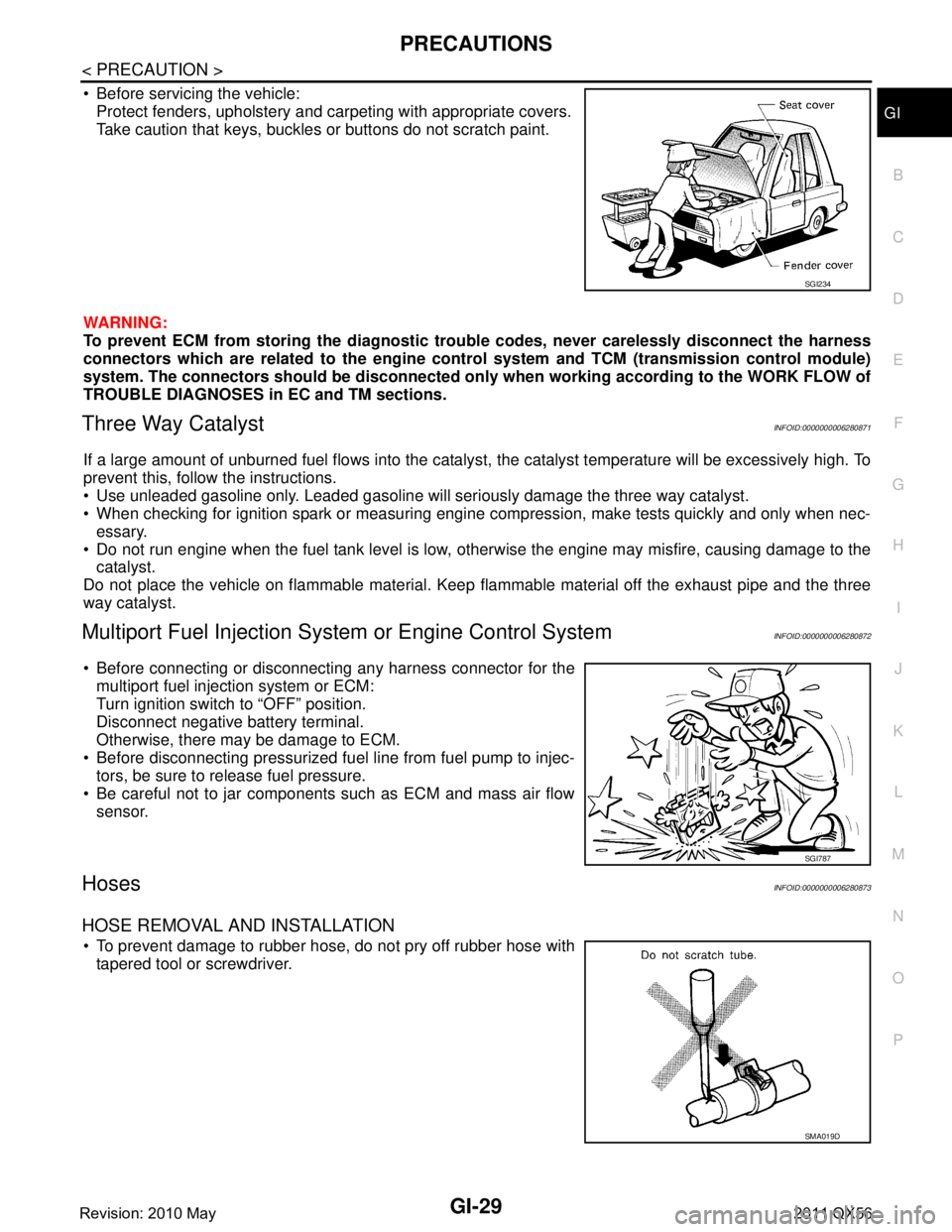
Before servicing the vehicle: Protect fenders, upholstery and carpeting with appropriate covers.
Take caution that keys, buckles or buttons do not scratch paint.
WARNING:
To prevent ECM from storing the diagnostic trou ble codes, never carelessly disconnect the harness
connectors which are related to the engine cont rol system and TCM (transmission control module)
system. The connectors should be disconnected only when working according to the WORK FLOW of
TROUBLE DIAGNOSES in EC and TM sections.
Three Way CatalystINFOID:0000000006280871
If a large amount of unburned fuel flows into the catalyst , the catalyst temperature will be excessively high. To
prevent this, follow the instructions.
Use unleaded gasoline only. Leaded gasoline will seriously damage the three way catalyst.
When checking for ignition spark or measuring engine compression, make tests quickly and only when nec- essary.
Do not run engine when the fuel tank level is low, otherwise the engine may misfire, causing damage to the
catalyst.
Do not place the vehicle on flammable material. Keep flammable material off the exhaust pipe and the three
way catalyst.
Multiport Fuel Inje ction System or Engine Control SystemINFOID:0000000006280872
Before connecting or disconnecti ng any harness connector for the
multiport fuel injection system or ECM:
Turn ignition switch to “OFF” position.
Disconnect negative battery terminal.
Otherwise, there may be damage to ECM.
Before disconnecting pressurized fuel line from fuel pump to injec- tors, be sure to release fuel pressure.
Be careful not to jar components such as ECM and mass air flow sensor.
HosesINFOID:0000000006280873
HOSE REMOVAL AND INSTALLATION
To prevent damage to rubber hose, do not pry off rubber hose withtapered tool or screwdriver.
SGI234
SGI787
SMA019D
Revision: 2010 May2011 QX56
Page 3451 of 5598
![INFINITI QX56 2011 Factory Service Manual
LAN
SYSTEMLAN-31
< SYSTEM DESCRIPTION > [CAN]
C
D
E
F
G H
I
J
K L
B A
O P
N
Meter display signal
TR
RT
Oil pressure switch signal TR
RT
Position light request signal T R R
Rear fog light status signa INFINITI QX56 2011 Factory Service Manual
LAN
SYSTEMLAN-31
< SYSTEM DESCRIPTION > [CAN]
C
D
E
F
G H
I
J
K L
B A
O P
N
Meter display signal
TR
RT
Oil pressure switch signal TR
RT
Position light request signal T R R
Rear fog light status signa](/manual-img/42/57033/w960_57033-3450.png)
LAN
SYSTEMLAN-31
< SYSTEM DESCRIPTION > [CAN]
C
D
E
F
G H
I
J
K L
B A
O P
N
Meter display signal
TR
RT
Oil pressure switch signal TR
RT
Position light request signal T R R
Rear fog light status signal T R
Rear window defogger con-
trol signal TR
RT
Sleep wake up signal T R R R R R R
Starter control relay signal T R
Starter relay status signal TRR
RT
Starting mode signal T R
Steering lock relay signal TRR
RT
Theft warning horn request
signal TR
Turn indicator signal R T R R
A/C display signal R T
A/C ON signal R T
Ambient temperature signal T R
Blower fan ON signal R T
Distance to empty signal R T
Fuel level low warning sig-
nal RT
Fuel level sensor signal R T
Manual mode shift down
signal RT
Manual mode shift up sig-
nal RT
Manual mode signal R T
Non-manual mode signal R T
Odometer signal R T
Parking brake switch signal R R T R R
Sleep-ready signal RT
RT
RT
Tow mode switch signal R T
Wake up signal RT
RT
Steering angle sensor mal-
function signal RR T R R
Steering angle sensor sig-
nal RR RR T R R
Steering angle speed signal R T R R Signal name
ECM
4WD
ABS
TCM
A-BAG AFS
AV
BCM
CGW
HVAC M&A
STRG
TPMS
IPDM-E
ADPPSB
E-SUS ICC
PWBD
Revision: 2010 May2011 QX56
Page 3686 of 5598
MA-16
< PERIODIC MAINTENANCE >
ENGINE MAINTENANCE
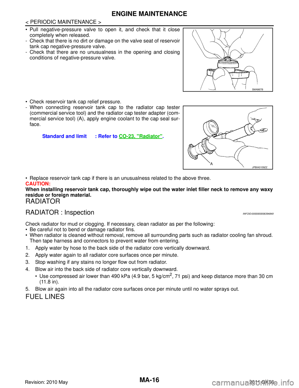
Pull negative-pressure valve to open it, and check that it closecompletely when released.
- Check that there is no dirt or damage on the valve seat of reservoir
tank cap negative-pressure valve.
- Check that there are no unusualness in the opening and closing conditions of negative-pressure valve.
Check reservoir tank cap relief pressure.
- When connecting reservoir tank cap to the radiator cap tester (commercial service tool) and the radiator cap tester adapter (com-
mercial service tool) (A), apply engine coolant to the cap seal sur-
face.
Replace reservoir tank cap if there is an unusualness related to the above three.
CAUTION:
When installing reservoir tank cap, thoroughly wipe out the water inlet filler neck to remove any waxy
residue or foreign material.
RADIATOR
RADIATOR : InspectionINFOID:0000000006394849
Check radiator for mud or clogging. If nec essary, clean radiator as per the following:
Be careful not to bend or damage radiator fins.
When radiator is cleaned without removal, remove all surrounding parts such as radiator cooling fan shroud. Then tape harness and connectors to prevent water from entering.
1. Apply water by hose to the back side of the radiator core vertically downward.
2. Apply water again to all radiator core surfaces once per minute.
3. Stop washing if any stains no longer flow out from radiator.
4. Blow air into the back side of radiator core vertically downward. Use compressed air lower than 490 kPa (4.9 bar, 5 kg/cm
2, 71 psi) and keep distance more than 30 cm
(11.8 in).
5. Blow air again into all the radiator core su rfaces once per minute until no water sprays out.
FUEL LINES
SMA967B
Standard and limit : Refer to CO-23, "Radiator".
JPBIA0109ZZ
Revision: 2010 May2011 QX56
Page 3744 of 5598
MWI
MWI-1
DRIVER INFORMATION & MULTIMEDIA
C
DE
F
G H
I
J
K L
M B
SECTION MWI
A
O P
CONTENTS
METER, WARNING LAMP & INDICATOR
PRECAUTION ................ ...............................4
PRECAUTIONS .............................................. .....4
Precaution for Supplemental Restraint System
(SRS) "AIR BAG" and "SEAT BELT PRE-TEN-
SIONER" ............................................................. ......
4
PREPARATION ............................................5
PREPARATION .............................................. .....5
Commercial Service Tools .................................. ......5
SYSTEM DESCRIPTION ..............................6
COMPONENT PARTS ................................... .....6
METER SYSTEM .........................................................6
METER SYSTEM : Component Parts Location .. ......6
METER SYSTEM : Component Description .............7
CLOCK .................................................................. ......7
CLOCK : Component Parts Location ........................8
SYSTEM ..............................................................9
METER SYSTEM .........................................................9
METER SYSTEM : System Diagram ........................9
METER SYSTEM : System Description ....................9
METER SYSTEM : Fail-Safe ..................................12
SPEEDOMETER ................ ........................................13
SPEEDOMETER : System Diagram ................... ....13
SPEEDOMETER : System Description ...................13
TACHOMETER ...................................................... ....13
TACHOMETER : System Diagram .........................14
TACHOMETER : System Description .....................14
ENGINE COOLANT TEMPERATURE GAUGE .... ....14
ENGINE COOLANT TEMPERATURE GAUGE :
System Diagram ......................................................
14
ENGINE COOLANT TEMPERATURE GAUGE :
System Description .................................................
14
FUEL GAUGE ........................................................ ....14
FUEL GAUGE : System Diagram ............................14
FUEL GAUGE : System Description .......................14
ENGINE OIL PRESSURE GAUGE ............................15
ENGINE OIL PRESSURE GAUGE : System Dia-
gram .................................................................... ....
15
ENGINE OIL PRESSURE GAUGE : System De-
scription ...................................................................
15
VOLTMETER ......................................................... ....15
VOLTMETER : System Diagram .............................15
VOLTMETER : System Description .........................15
OIL PRESSURE WARNING LAMP ...........................15
OIL PRESSURE WARNING LAMP : System Dia-
gram .................................................................... ....
15
OIL PRESSURE WARNING LAMP : System De-
scription ...................................................................
16
MASTER WARNING LAMP ................................... ....16
MASTER WARNING LAMP : System Diagram .......16
MASTER WARNING LAMP : System Description ....16
METER ILLUMINATION CONTROL ..................... ....16
METER ILLUMINATION CONTROL : System Di-
agram ......................................................................
16
METER ILLUMINATION CONTROL : System De-
scription ...................................................................
16
METER EFFECT FUNCTION ................................ ....17
METER EFFECT FUNCTION : System Diagram ....17
METER EFFECT FUNCTION : System Descrip-
tion ...........................................................................
17
INFORMATION DISPLAY ...................................... ....19
INFORMATION DISPLAY : System Diagram ..........19
INFORMATION DISPLAY : System Description .....20
OPERATION .....................................................28
Switch Name and Function ......................................28
Revision: 2010 May2011 QX56
Page 3745 of 5598

MWI-2
DIAGNOSIS SYSTEM (COMBINATION
METER) ..............................................................
29
On Board Diagnosis Function .............................. ...29
CONSULT-III Function ...........................................30
ECU DIAGNOSIS INFORMATION ..............35
COMBINATION METER ................................. ...35
Reference Value .................................................. ...35
Fail-Safe .................................................................42
DTC Index ..............................................................43
IPDM E/R ...........................................................44
List of ECU Reference ......................................... ...44
WIRING DIAGRAM .....................................45
METER SYSTEM ............................................ ...45
Wiring Diagram .................................................... ...45
CLOCK ...............................................................55
Wiring Diagram .................................................... ...55
BASIC INSPECTION ...................................57
DIAGNOSIS AND REPAIR WORKFLOW
(METER SYSTEM ) .......................................... ...
57
Work flow ............................................................. ...57
DTC/CIRCUIT DIAGNOSIS ...................... ...59
U1000 CAN COMM CIRCUIT ......................... ...59
Description ........................................................... ...59
DTC Logic ...............................................................59
Diagnosis Procedure .............................................59
U1010 CONTROL UNIT (CAN) .........................60
Description ........................................................... ...60
DTC Logic ...............................................................60
Diagnosis Procedure ..............................................60
B2205 VEHICLE SPEED ...................................61
Description ........................................................... ...61
DTC Logic ...............................................................61
Diagnosis Procedure .............................................61
B2267 ENGINE SPEED .....................................62
Description ........................................................... ...62
DTC Logic ...............................................................62
Diagnosis Procedure ..............................................62
B2268 WATER TEMP ........................................63
Description ........................................................... ...63
DTC Logic ...............................................................63
Diagnosis Procedure ..............................................63
POWER SUPPLY AND GROUND CIRCUIT .....64
COMBINATION METER ........................................ ...64
COMBINATION METER : Diagnosis Procedure ....64
TRIP RESET AND ILLUMINATION CON-
TROL SWITCH SIGNAL CIRCUIT ....................
65
Diagnosis Procedure ............................................ ...65
Component Inspection ............................................66
TRIP COMPUTER SWITCH SIGNAL CIRCUIT
...
67
Diagnosis Procedure ............................................ ...67
Component Inspection ............................................68
FUEL LEVEL SENSOR SIGNAL CIRCUIT .......69
Component Function Check ................................ ...69
Diagnosis Procedure ..............................................69
Component Inspection ............................................70
OIL PRESSURE SWITCH SIGNAL CIRCUIT ...71
Component Function Check ...................................71
Diagnosis Procedure ...............................................71
Component Inspection ............................................71
WASHER LEVEL SWITCH SIGNAL CIRCUIT ...73
Diagnosis Procedure ............................................ ...73
Component Inspection ............................................73
A/C AUTO AMP. CONNECTION RECOGNI-
TION SIGNAL CIRCUIT ....................................
74
Diagnosis Procedure ........................................... ...74
SYMPTOM DIAGNOSIS ............................75
THE FUEL GAUGE INDICATOR DOES NOT
OPERATE ....................................................... ...
75
Description ........................................................... ...75
Diagnosis Procedure ...............................................75
THE TRIP RESET AND ILLUMINATION CON-
TROL SWITCH IS INOPERATIVE ....................
76
Description ........................................................... ...76
Diagnosis Procedure ...............................................76
THE TRIP COMPUTER SWITCH IS INOPER-
ATIVE .................................................................
77
Description ........................................................... ...77
Diagnosis Procedure ...............................................77
THE OIL PRESSURE WARNING LAMP
DOES NOT TURN ON .................................... ...
78
Description ........................................................... ...78
Diagnosis Procedure ...............................................78
THE OIL PRESSURE WARNING LAMP
DOES NOT TURN OFF .................................. ...
79
Description ........................................................... ...79
Diagnosis Procedure ...............................................79
THE PARKING BRAKE RELEASE WARNING
CONTINUES DISPLAYING, OR DOES NOT
DISPLAY ............................................................
80
Description ........................................................... ...80
Diagnosis Procedure ...............................................80
Revision: 2010 May2011 QX56
Page 3749 of 5598
MWI-6
< SYSTEM DESCRIPTION >
COMPONENT PARTS
SYSTEM DESCRIPTION
COMPONENT PARTS
METER SYSTEM
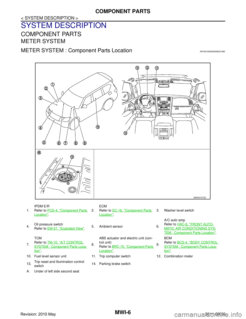
METER SYSTEM : Component Parts LocationINFOID:0000000006221690
1.IPDM E/R
Refer to
PCS-4, "Component Parts
Location". 2.
ECM
Refer to
EC-16, "
Component Parts
Location". 3. Washer level switch
4. Oil pressure switch
Refer to
EM-57, "
Exploded View".5. Ambient sensor 6. A/C auto amp.
Refer to
HAC-6, "
FRONT AUTO-
MATIC AIR CONDITIONING SYS-
TEM : Component Parts Location".
7. TCM
Refer to
TM-10, "
A/T CONTROL
SYSTEM : Componen t Parts Loca-
tion". 8.ABS actuator and electric unit (con-
trol unit)
Refer to
BRC-10, "
Component Parts
Location". 9.BCM
Refer to
BCS-4, "
BODY CONTROL
SYSTEM : Component Parts Loca-
tion".
10. Fuel level sensor unit 11. Trip computer switch 12. Combination meter
13. Trip reset and illumination control
switch 14. Parking brake switch
A. Under of left side second seat
JSNIA3157ZZ
Revision: 2010 May2011 QX56
Page 3750 of 5598
MWI
COMPONENT PARTSMWI-7
< SYSTEM DESCRIPTION >
C
DE
F
G H
I
J
K L
M B A
O P
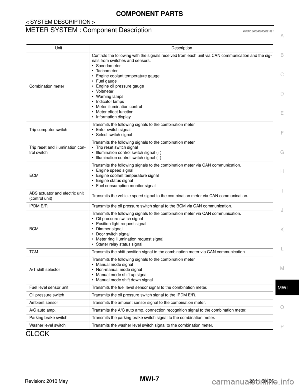
METER SYSTEM : Com ponent DescriptionINFOID:0000000006221691
CLOCK
Unit Description
Combination meter Controls the following with the signals received from each unit via CAN communication and the sig-
nals from switches and sensors.
Speedometer
Tachometer
Engine coolant temperature gauge
Fuel gauge
Engine oil pressure gauge
Voltmeter
Warning lamps
Indicator lamps
Meter illumination control
Meter effect function
Information display
Trip computer switch Transmits the following signals to the combination meter.
Enter switch signal
Select switch signal
Trip reset and illumination con-
trol switch Transmits the following signals to the combination meter.
Trip reset switch signal
Illumination control switch signal (+)
Illumination control switch signal (
−)
ECM Transmits the following signals to the combination meter via CAN communication.
Engine speed signal
Engine coolant temperature signal
Engine status signal
Fuel consumption monitor signal
ABS actuator and electric unit
(control unit) Transmits the vehicle speed signal to the combination meter via CAN communication.
IPDM E/R Transmits the oil pressure switch signal to the BCM via CAN communication.
BCM Transmits the following signals to the combination meter via CAN communication.
Oil pressure switch signal
Position light request signal
Dimmer signal
Door switch signal
Meter ring illumination request signal
Starter relay status signal
TCM Transmits the shift position signal to the combination meter via CAN communication.
A/T shift selector Transmits the following signals to the combination meter.
Manual mode signal
Non-manual mode signal
Manual mode shift up signal
Manual mode shift down signal
Fuel level sensor unit Transmits the fuel level sensor signal to the combination meter.
Oil pressure switch Transmits the oil pressure switch signal to the IPDM E/R.
Ambient sensor Transmits the ambient sensor signal to the combination meter.
A/C auto amp. Transmits the A/C auto amp. connection recognition signal to the combination meter.
Parking brake switch Transmits the parking brake switch signal to the combination meter.
Washer level switch Transmits the washer level switch signal to the combination meter.
Revision: 2010 May2011 QX56
Page 3753 of 5598
MWI-10
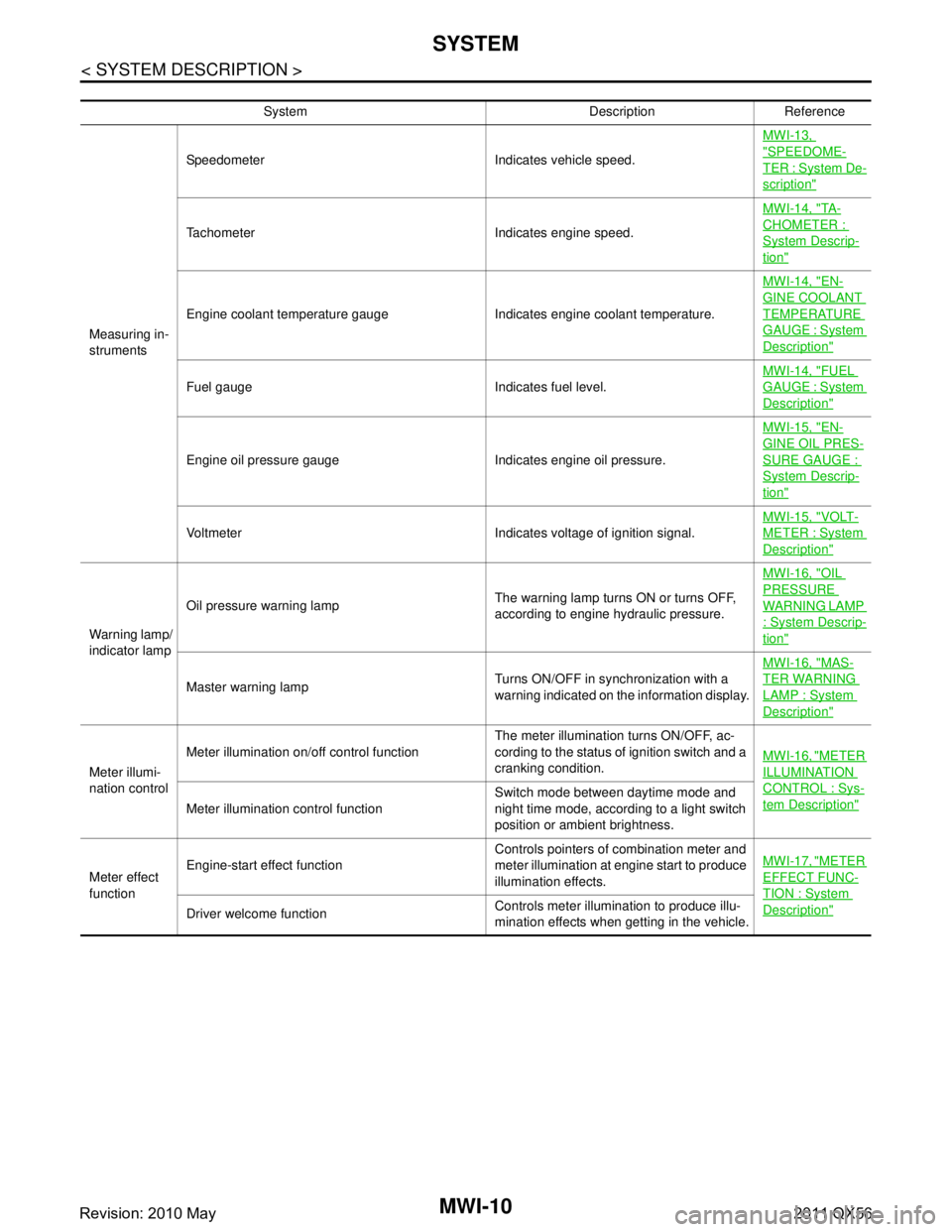
< SYSTEM DESCRIPTION >
SYSTEM
System Description Reference
Measuring in-
struments Speedometer Indicates vehicle speed.
MWI-13,
"SPEEDOME-
TER : System De-
scription"
Tachometer Indicates engine speed.MWI-14, "
TA -
CHOMETER :
System Descrip-
tion"
Engine coolant temperature gauge Indicates engine coolant temperature.MWI-14, "
EN-
GINE COOLANT
TEMPERATURE
GAUGE : System
Description"
Fuel gauge Indicates fuel level.
MWI-14, "
FUEL
GAUGE : System
Description"
Engine oil pressure gauge Indicates engine oil pressure.MWI-15, "
EN-
GINE OIL PRES-
SURE GAUGE :
System Descrip-
tion"
Voltmeter Indicates voltage of ignition signal.
MWI-15, "
VOLT-
METER : System
Description"
Warning lamp/
indicator lampOil pressure warning lamp
The warning lamp turns ON or turns OFF,
according to engine hydraulic pressure.MWI-16, "
OIL
PRESSURE
WARNING LAMP
: System Descrip-
tion"
Master warning lamp
Turns ON/OFF in synchronization with a
warning indicated on the information display.MWI-16, "
MAS-
TER WARNING
LAMP : System
Description"
Meter illumi-
nation controlMeter illumination on/off control function
The meter illumination turns ON/OFF, ac-
cording to the status of ignition switch and a
cranking condition.
MWI-16, "
METER
ILLUMINATION
CONTROL : Sys-
tem Description"Meter illumination control function Switch mode between daytime mode and
night time mode, according to a light switch
position or ambient brightness.
Meter effect
function Engine-start effect function
Controls pointers of combination meter and
meter illumination at engine start to produce
illumination effects.MWI-17, "
METER
EFFECT FUNC-
TION : System
Description"Driver welcome function
Controls meter illumination to produce illu-
mination effects when getting in the vehicle.
Revision: 2010 May2011 QX56