2011 INFINITI QX56 engine coolant
[x] Cancel search: engine coolantPage 3683 of 5598
ENGINE MAINTENANCEMA-13
< PERIODIC MAINTENANCE >
C
DE
F
G H
I
J
K L
M B
MA
N
O A
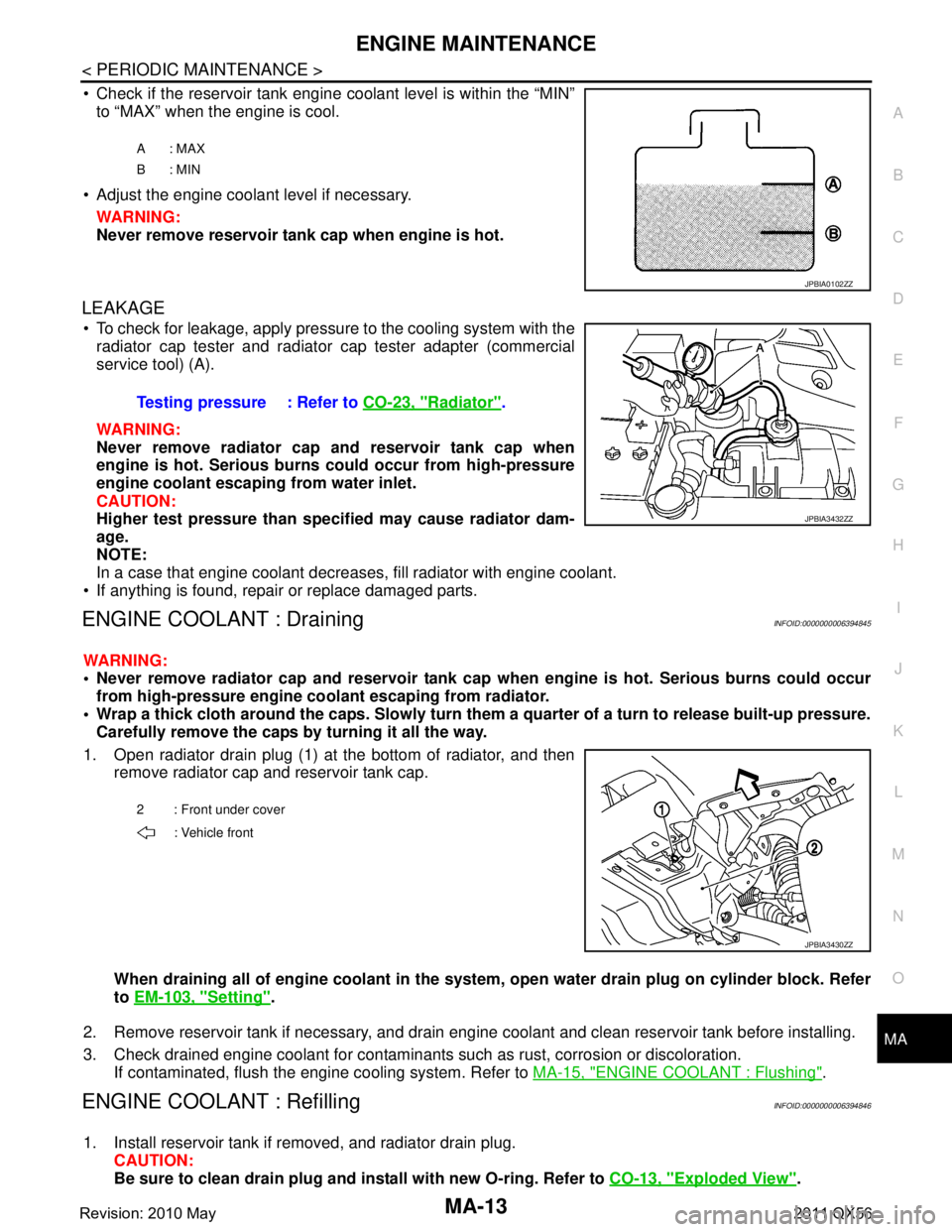
Check if the reservoir tank engine coolant level is within the “MIN”
to “MAX” when the engine is cool.
Adjust the engine coolant level if necessary. WARNING:
Never remove reservoir tank cap when engine is hot.
LEAKAGE
To check for leakage, apply pressure to the cooling system with theradiator cap tester and radiator cap tester adapter (commercial
service tool) (A).
WARNING:
Never remove radiator cap and reservoir tank cap when
engine is hot. Serious burns could occur from high-pressure
engine coolant escaping from water inlet.
CAUTION:
Higher test pressure than specified may cause radiator dam-
age.
NOTE:
In a case that engine coolant decreas es, fill radiator with engine coolant.
If anything is found, repair or replace damaged parts.
ENGINE COOLANT : DrainingINFOID:0000000006394845
WARNING:
Never remove radiator cap and reservoir tank cap when engine is hot. Serious burns could occur
from high-pressure engine co olant escaping from radiator.
Wrap a thick cloth around the caps. Slowly turn them a quarter of a turn to release built-up pressure.
Carefully remove the caps by turning it all the way.
1. Open radiator drain plug (1) at the bottom of radiator, and then remove radiator cap and reservoir tank cap.
When draining all of engine cool ant in the system, open water drai n plug on cylinder block. Refer
to EM-103, "
Setting".
2. Remove reservoir tank if necessary, and drain engine coolant and clean reservoir tank before installing.
3. Check drained engine coolant for contaminants such as rust, corrosion or discoloration. If contaminated, flush the engine cooling system. Refer to MA-15, "
ENGINE COOLANT : Flushing".
ENGINE COOLANT : RefillingINFOID:0000000006394846
1. Install reservoir tank if removed, and radiator drain plug.
CAUTION:
Be sure to clean drain plug and install with new O-ring. Refer to CO-13, "
Exploded View".
A: MAX
B: MIN
JPBIA0102ZZ
Testing pressure : Refer to CO-23, "Radiator".
JPBIA3432ZZ
2 : Front under cover
: Vehicle front
JPBIA3430ZZ
Revision: 2010 May2011 QX56
Page 3684 of 5598
MA-14
< PERIODIC MAINTENANCE >
ENGINE MAINTENANCE
If water drain plug on cylinder block is removed, close and tighten it. Refer to EM-107, "Disassem-
bly and Assembly".
2. Check that each hose clamp is firmly tightened.
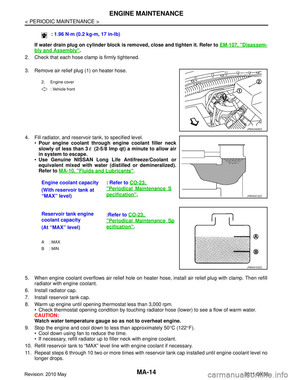
3. Remove air relief plug (1) on heater hose.
4. Fill radiator, and reservoir tank, to specified level. Pour engine coolant through engine coolant filler neck
slowly of less than 3 (2-5/8 lmp qt) a minute to allow air
in system to escape.
Use Genuine NISSAN Long Life Antifreeze/Coolant or
equivalent mixed with water (d istilled or demineralized).
Refer to MA-10, "
Fluids and Lubricants".
5. When engine coolant overflows air relief hole on heater hose, install air relief plug with clamp. Then refill
radiator with engine coolant.
6. Install radiator cap.
7. Install reservoir tank cap.
8. Warm up engine until opening thermostat less than 3,000 rpm. Check thermostat opening condition by touching radiator hose (lower) to see a flow of warm water.
CAUTION:
Watch water temperature gauge so as not to overheat engine.
9. Stop the engine and cool down to less than approximately 50 °C (122 °F).
Cool down using fan to reduce the time.
If necessary, refill radiator up to filler neck with engine coolant.
10. Refill reservoir tank to “MAX” level line with engine coolant if necessary.
11. Repeat steps 6 through 10 two or more times with reservoir tank cap installed until engine coolant level no longer drops. : 1.96 N·m (0.2 kg-m, 17 in-lb)
2. Engine cover
: Vehicle front
JPBIA3429ZZ
Engine coolant capacity : Refer to CO-23,
"PeriodicalMaintenanceS
pecification".
(With reservoir tank at
“MAX” level)JPBIA0412ZZ
Reservoir tank engine
coolant capacity :Refer to
CO-23,
"PeriodicalMaintenanceSp
ecification".
(At “MAX” level)
A : MAX
B: MIN
JPBIA0102ZZ
Revision: 2010 May2011 QX56
Page 3685 of 5598
ENGINE MAINTENANCEMA-15
< PERIODIC MAINTENANCE >
C
DE
F
G H
I
J
K L
M B
MA
N
O A
12. Check cooling system for leakage with engine running.
13. Warm up the engine, and check for sound of engine coolant flow while running engine from idle up to
3,000 rpm with heater temperature controller se t at several position between “COOL” and “WARM”.
Sound may be noticeable at heater unit.
14. Repeat step 13 three times.
15. If sound is heard, bleed air from cooling system by repeating step 4, and steps from 6 to 14 until engine
coolant level no longer drops.
ENGINE COOLANT : FlushingINFOID:0000000006394847
1. Install reservoir tank if removed, and radiator drain plug. CAUTION:
Be sure to clean drain plug and install with new O-ring. Refer to CO-13, "
Exploded View".
If water drain plug on cylinder block is removed, close and tighten it. Refer to EM-107, "
Disassem-
bly and Assembly".
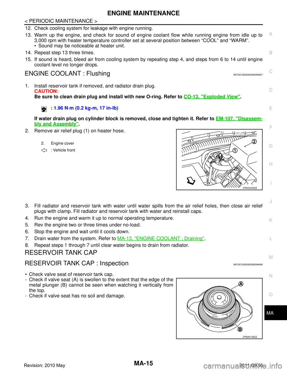
2. Remove air relief plug (1) on heater hose.
3. Fill radiator and reservoir tank with water until water spills from the air relief holes, then close air relief
plugs with clamp. Fill radiator and rese rvoir tank with water and reinstall caps.
4. Run the engine and warm it up to normal operating temperature.
5. Rev the engine two or three times under no-load.
6. Stop the engine and wait until it cools down.
7. Drain water from the system. Refer to MA-13, "
ENGINE COOLANT : Draining".
8. Repeat steps 1 through 7 until clear water begins to drain from radiator.
RESERVOIR TANK CAP
RESERVOIR TANK CAP : InspectionINFOID:0000000006394848
Check valve seat of reservoir tank cap.
- Check if valve seat (A) is swollen to the extent that the edge of the metal plunger (B) cannot be seen when watching it vertically from
the top.
- Check if valve seat has no soil and damage. : 1.96 N·m (0.2 kg-m, 17 in-lb)
2. Engine cover
: Vehicle front
JPBIA3429ZZ
JPBIA0108ZZ
Revision: 2010 May2011 QX56
Page 3686 of 5598
MA-16
< PERIODIC MAINTENANCE >
ENGINE MAINTENANCE
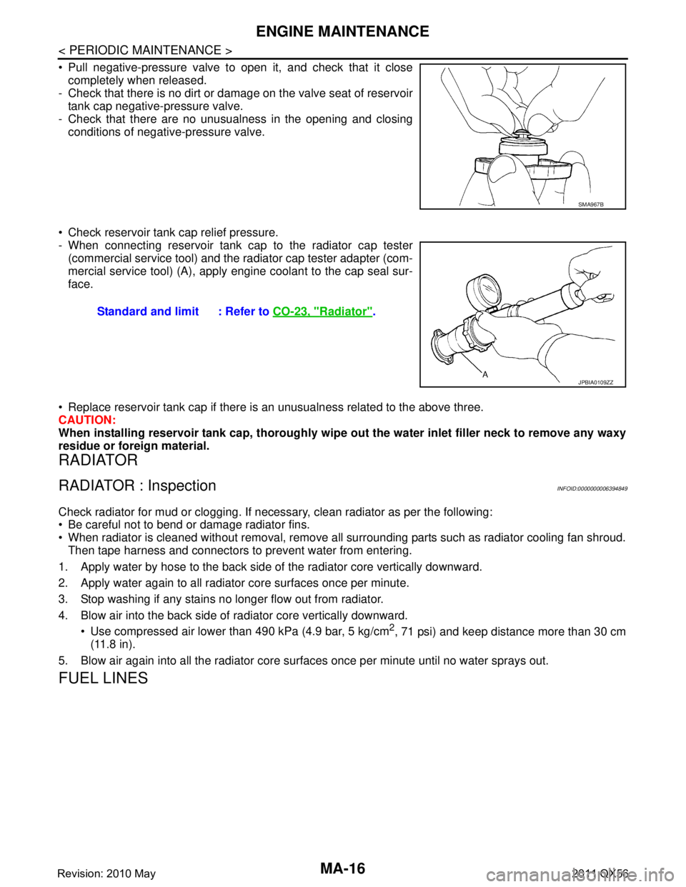
Pull negative-pressure valve to open it, and check that it closecompletely when released.
- Check that there is no dirt or damage on the valve seat of reservoir
tank cap negative-pressure valve.
- Check that there are no unusualness in the opening and closing conditions of negative-pressure valve.
Check reservoir tank cap relief pressure.
- When connecting reservoir tank cap to the radiator cap tester (commercial service tool) and the radiator cap tester adapter (com-
mercial service tool) (A), apply engine coolant to the cap seal sur-
face.
Replace reservoir tank cap if there is an unusualness related to the above three.
CAUTION:
When installing reservoir tank cap, thoroughly wipe out the water inlet filler neck to remove any waxy
residue or foreign material.
RADIATOR
RADIATOR : InspectionINFOID:0000000006394849
Check radiator for mud or clogging. If nec essary, clean radiator as per the following:
Be careful not to bend or damage radiator fins.
When radiator is cleaned without removal, remove all surrounding parts such as radiator cooling fan shroud. Then tape harness and connectors to prevent water from entering.
1. Apply water by hose to the back side of the radiator core vertically downward.
2. Apply water again to all radiator core surfaces once per minute.
3. Stop washing if any stains no longer flow out from radiator.
4. Blow air into the back side of radiator core vertically downward. Use compressed air lower than 490 kPa (4.9 bar, 5 kg/cm
2, 71 psi) and keep distance more than 30 cm
(11.8 in).
5. Blow air again into all the radiator core su rfaces once per minute until no water sprays out.
FUEL LINES
SMA967B
Standard and limit : Refer to CO-23, "Radiator".
JPBIA0109ZZ
Revision: 2010 May2011 QX56
Page 3705 of 5598
SERVICE DATA AND SPECIFICATIONS (SDS)
MA-35
< SERVICE DATA AND SPECIFICATIONS (SDS)
C
D E
F
G H
I
J
K L
M B
MA
N
O A
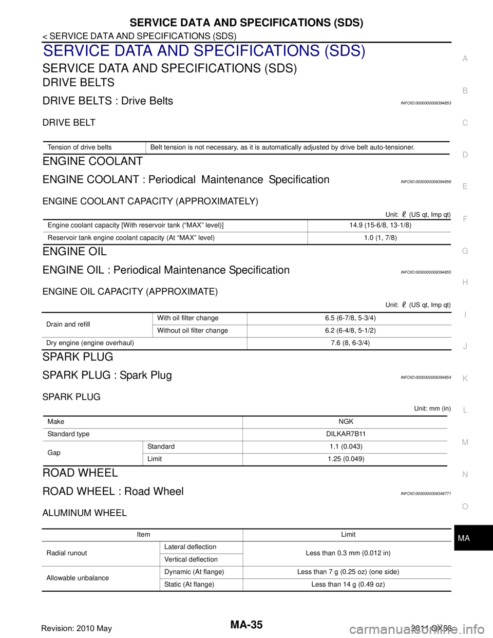
SERVICE DATA AND SPECIFICATIONS (SDS)
SERVICE DATA AND SPECIFICATIONS (SDS)
DRIVE BELTS
DRIVE BELTS : Drive BeltsINFOID:0000000006394853
DRIVE BELT
ENGINE COOLANT
ENGINE COOLANT : Periodical Maintenance SpecificationINFOID:0000000006394856
ENGINE COOLANT CAPACITY (APPROXIMATELY)
Unit: (US qt, Imp qt)
ENGINE OIL
ENGINE OIL : Periodical Maintenance SpecificationINFOID:0000000006394855
ENGINE OIL CAPACITY (APPROXIMATE)
Unit: (US qt, Imp qt)
SPARK PLUG
SPARK PLUG : Spark PlugINFOID:0000000006394854
SPARK PLUG
Unit: mm (in)
ROAD WHEEL
ROAD WHEEL : Road WheelINFOID:0000000006349771
ALUMINUM WHEEL
Tension of drive belts Belt tension is not necessary, as it is automatically adjusted by drive belt auto-tensioner.
Engine coolant capacity [With reservoir tank (“MAX” level)] 14.9 (15-6/8, 13-1/8)
Reservoir tank engine coolant capacity (At “MAX” level) 1.0 (1, 7/8)
Drain and refill
With oil filter change 6.5 (6-7/8, 5-3/4)
Without oil filter change 6.2 (6-4/8, 5-1/2)
Dry engine (engine overhaul) 7.6 (8, 6-3/4)
Make NGK
Standard type DILKAR7B11
Gap Standard 1.1 (0.043)
Limit 1.25 (0.049)
Item Limit
Radial runout Lateral deflection
Less than 0.3 mm (0.012 in)
Vertical deflection
Allowable unbalance Dynamic (At flange) Less than 7 g (0.25 oz) (one side)
Static (At flange) Less than 14 g (0.49 oz)
Revision: 2010 May2011 QX56
Page 3744 of 5598
MWI
MWI-1
DRIVER INFORMATION & MULTIMEDIA
C
DE
F
G H
I
J
K L
M B
SECTION MWI
A
O P
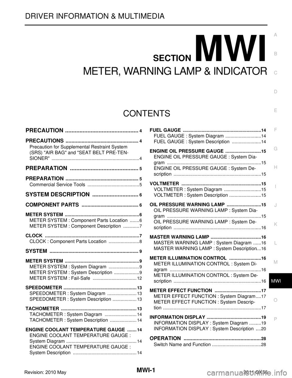
CONTENTS
METER, WARNING LAMP & INDICATOR
PRECAUTION ................ ...............................4
PRECAUTIONS .............................................. .....4
Precaution for Supplemental Restraint System
(SRS) "AIR BAG" and "SEAT BELT PRE-TEN-
SIONER" ............................................................. ......
4
PREPARATION ............................................5
PREPARATION .............................................. .....5
Commercial Service Tools .................................. ......5
SYSTEM DESCRIPTION ..............................6
COMPONENT PARTS ................................... .....6
METER SYSTEM .........................................................6
METER SYSTEM : Component Parts Location .. ......6
METER SYSTEM : Component Description .............7
CLOCK .................................................................. ......7
CLOCK : Component Parts Location ........................8
SYSTEM ..............................................................9
METER SYSTEM .........................................................9
METER SYSTEM : System Diagram ........................9
METER SYSTEM : System Description ....................9
METER SYSTEM : Fail-Safe ..................................12
SPEEDOMETER ................ ........................................13
SPEEDOMETER : System Diagram ................... ....13
SPEEDOMETER : System Description ...................13
TACHOMETER ...................................................... ....13
TACHOMETER : System Diagram .........................14
TACHOMETER : System Description .....................14
ENGINE COOLANT TEMPERATURE GAUGE .... ....14
ENGINE COOLANT TEMPERATURE GAUGE :
System Diagram ......................................................
14
ENGINE COOLANT TEMPERATURE GAUGE :
System Description .................................................
14
FUEL GAUGE ........................................................ ....14
FUEL GAUGE : System Diagram ............................14
FUEL GAUGE : System Description .......................14
ENGINE OIL PRESSURE GAUGE ............................15
ENGINE OIL PRESSURE GAUGE : System Dia-
gram .................................................................... ....
15
ENGINE OIL PRESSURE GAUGE : System De-
scription ...................................................................
15
VOLTMETER ......................................................... ....15
VOLTMETER : System Diagram .............................15
VOLTMETER : System Description .........................15
OIL PRESSURE WARNING LAMP ...........................15
OIL PRESSURE WARNING LAMP : System Dia-
gram .................................................................... ....
15
OIL PRESSURE WARNING LAMP : System De-
scription ...................................................................
16
MASTER WARNING LAMP ................................... ....16
MASTER WARNING LAMP : System Diagram .......16
MASTER WARNING LAMP : System Description ....16
METER ILLUMINATION CONTROL ..................... ....16
METER ILLUMINATION CONTROL : System Di-
agram ......................................................................
16
METER ILLUMINATION CONTROL : System De-
scription ...................................................................
16
METER EFFECT FUNCTION ................................ ....17
METER EFFECT FUNCTION : System Diagram ....17
METER EFFECT FUNCTION : System Descrip-
tion ...........................................................................
17
INFORMATION DISPLAY ...................................... ....19
INFORMATION DISPLAY : System Diagram ..........19
INFORMATION DISPLAY : System Description .....20
OPERATION .....................................................28
Switch Name and Function ......................................28
Revision: 2010 May2011 QX56
Page 3750 of 5598
MWI
COMPONENT PARTSMWI-7
< SYSTEM DESCRIPTION >
C
DE
F
G H
I
J
K L
M B A
O P
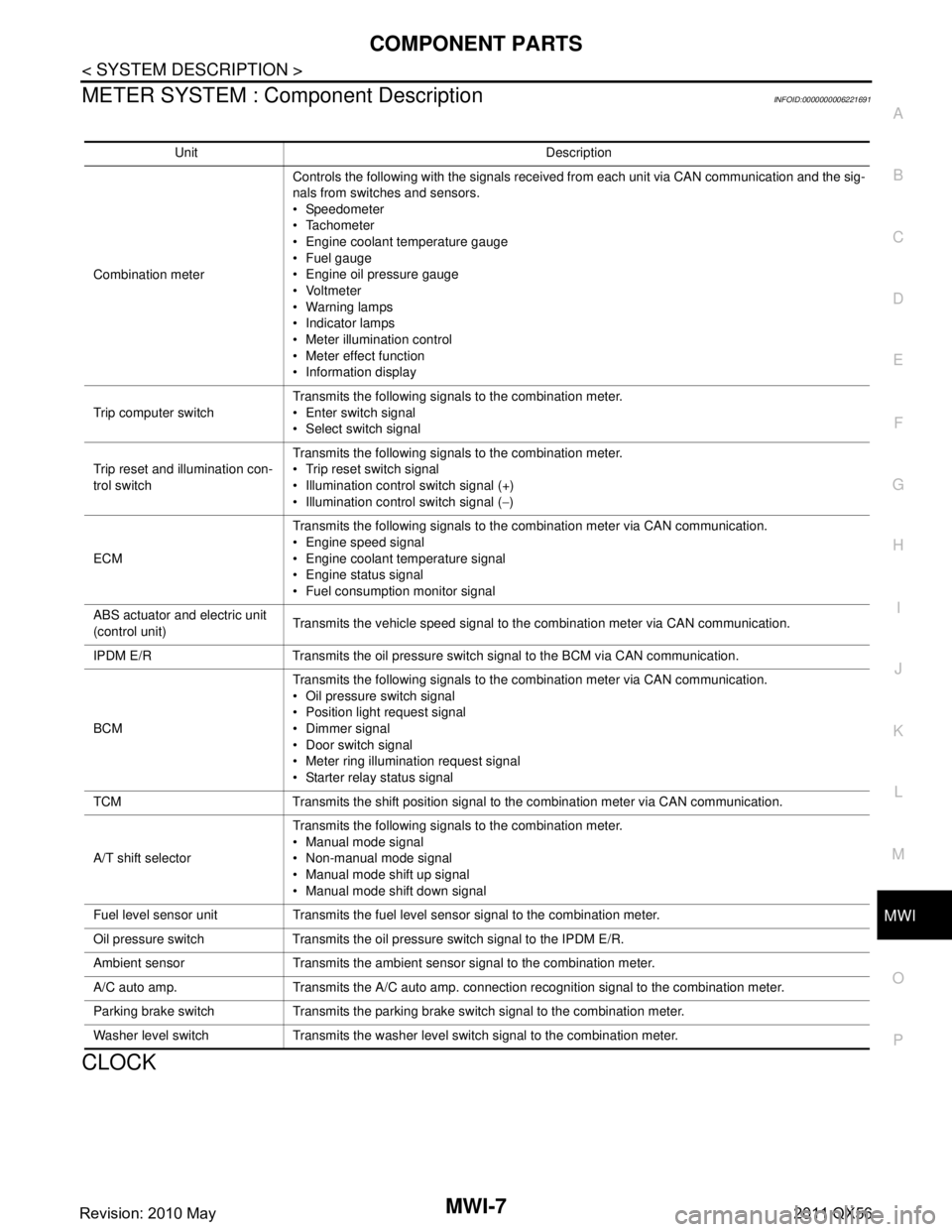
METER SYSTEM : Com ponent DescriptionINFOID:0000000006221691
CLOCK
Unit Description
Combination meter Controls the following with the signals received from each unit via CAN communication and the sig-
nals from switches and sensors.
Speedometer
Tachometer
Engine coolant temperature gauge
Fuel gauge
Engine oil pressure gauge
Voltmeter
Warning lamps
Indicator lamps
Meter illumination control
Meter effect function
Information display
Trip computer switch Transmits the following signals to the combination meter.
Enter switch signal
Select switch signal
Trip reset and illumination con-
trol switch Transmits the following signals to the combination meter.
Trip reset switch signal
Illumination control switch signal (+)
Illumination control switch signal (
−)
ECM Transmits the following signals to the combination meter via CAN communication.
Engine speed signal
Engine coolant temperature signal
Engine status signal
Fuel consumption monitor signal
ABS actuator and electric unit
(control unit) Transmits the vehicle speed signal to the combination meter via CAN communication.
IPDM E/R Transmits the oil pressure switch signal to the BCM via CAN communication.
BCM Transmits the following signals to the combination meter via CAN communication.
Oil pressure switch signal
Position light request signal
Dimmer signal
Door switch signal
Meter ring illumination request signal
Starter relay status signal
TCM Transmits the shift position signal to the combination meter via CAN communication.
A/T shift selector Transmits the following signals to the combination meter.
Manual mode signal
Non-manual mode signal
Manual mode shift up signal
Manual mode shift down signal
Fuel level sensor unit Transmits the fuel level sensor signal to the combination meter.
Oil pressure switch Transmits the oil pressure switch signal to the IPDM E/R.
Ambient sensor Transmits the ambient sensor signal to the combination meter.
A/C auto amp. Transmits the A/C auto amp. connection recognition signal to the combination meter.
Parking brake switch Transmits the parking brake switch signal to the combination meter.
Washer level switch Transmits the washer level switch signal to the combination meter.
Revision: 2010 May2011 QX56
Page 3753 of 5598
MWI-10
< SYSTEM DESCRIPTION >
SYSTEM
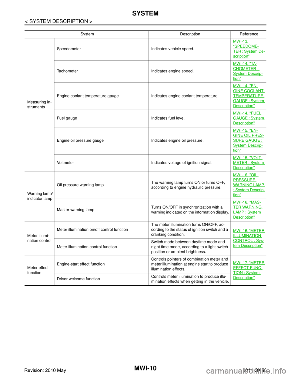
System Description Reference
Measuring in-
struments Speedometer Indicates vehicle speed.
MWI-13,
"SPEEDOME-
TER : System De-
scription"
Tachometer Indicates engine speed.MWI-14, "
TA -
CHOMETER :
System Descrip-
tion"
Engine coolant temperature gauge Indicates engine coolant temperature.MWI-14, "
EN-
GINE COOLANT
TEMPERATURE
GAUGE : System
Description"
Fuel gauge Indicates fuel level.
MWI-14, "
FUEL
GAUGE : System
Description"
Engine oil pressure gauge Indicates engine oil pressure.MWI-15, "
EN-
GINE OIL PRES-
SURE GAUGE :
System Descrip-
tion"
Voltmeter Indicates voltage of ignition signal.
MWI-15, "
VOLT-
METER : System
Description"
Warning lamp/
indicator lampOil pressure warning lamp
The warning lamp turns ON or turns OFF,
according to engine hydraulic pressure.MWI-16, "
OIL
PRESSURE
WARNING LAMP
: System Descrip-
tion"
Master warning lamp
Turns ON/OFF in synchronization with a
warning indicated on the information display.MWI-16, "
MAS-
TER WARNING
LAMP : System
Description"
Meter illumi-
nation controlMeter illumination on/off control function
The meter illumination turns ON/OFF, ac-
cording to the status of ignition switch and a
cranking condition.
MWI-16, "
METER
ILLUMINATION
CONTROL : Sys-
tem Description"Meter illumination control function Switch mode between daytime mode and
night time mode, according to a light switch
position or ambient brightness.
Meter effect
function Engine-start effect function
Controls pointers of combination meter and
meter illumination at engine start to produce
illumination effects.MWI-17, "
METER
EFFECT FUNC-
TION : System
Description"Driver welcome function
Controls meter illumination to produce illu-
mination effects when getting in the vehicle.
Revision: 2010 May2011 QX56