2011 INFINITI QX56 engine coolant
[x] Cancel search: engine coolantPage 3448 of 5598
![INFINITI QX56 2011 Factory Service Manual
LAN-28
< SYSTEM DESCRIPTION >[CAN]
SYSTEM
Check CAN system type from the vehicle shape and equipment.
CAN COMMUNICATION SYSTEM : CA
N Communication Signal ChartINFOID:0000000006220533
Refer to LAN-17 INFINITI QX56 2011 Factory Service Manual
LAN-28
< SYSTEM DESCRIPTION >[CAN]
SYSTEM
Check CAN system type from the vehicle shape and equipment.
CAN COMMUNICATION SYSTEM : CA
N Communication Signal ChartINFOID:0000000006220533
Refer to LAN-17](/manual-img/42/57033/w960_57033-3447.png)
LAN-28
< SYSTEM DESCRIPTION >[CAN]
SYSTEM
Check CAN system type from the vehicle shape and equipment.
CAN COMMUNICATION SYSTEM : CA
N Communication Signal ChartINFOID:0000000006220533
Refer to LAN-17, "How to Use CAN Communication Signal Chart" for how to use CAN communication signal
chart.
T: Transmit R: Receive
1. ICC sensor
A. With ICC system
JSMIA0342ZZ
Signal nameECM
4WD
ABS
TCM
A-BAG
AFSAV
BCM
CGW
HVAC
M&A
STRG
TPMS
IPDM-E ADP
PSB
E-SUS ICC
PWBD
A/C compressor request
signal TR
Accelerator pedal position
signal TRRR
R
ASCD OD cancel request
signal TR
ASCD operation signal T R
ASCD status signal T R
Closed throttle position sig-
nal TR
R
Cooling fan speed request
signal TR
Engine and A/T integrated
control signal TR
RT
Engine coolant temperature
signal TRR
Engine restart request sig-
nal TRR
TR
Engine speed signal T R R R R R R R
Engine status signal T R R R
Engine torque signal T R
Fuel consumption monitor
signal TRR
ICC brake switch signal T R
ICC prohibition signal T R
ICC steering switch signal T R
Malfunctioning indicator
lamp signal TR
N idle instruction signal TR
RT
Revision: 2010 May2011 QX56
Page 3655 of 5598
LU-2
< PRECAUTION >
PRECAUTIONS
PRECAUTION
PRECAUTIONS
Liquid GasketINFOID:0000000006289611
LIQUID GASKET APPLICATION PROCEDURE
1. Remove old liquid gasket adhering to the liquid gasket application surface and the mating surface.• Remove liquid gasket completely from the liquid gasket application surface, mounting bolts, and boltholes.
2. Wipe the liquid gasket application surface and the ma ting surface with white gasoline (lighting and heating
use) to remove adhering moisture, grease and foreign materials.
3. Apply liquid gasket to the liquid gasket application surface. Use Genuine RTV Silicone Seal ant or equivalent. Refer to GI-22, "
Recommended Chemical Prod-
ucts and Sealants".
Within five minutes of liquid gasket application, install the mating component.
If liquid gasket protrudes, wipe it off immediately.
Do not retighten mounting bolts or nuts after the installation.
After 30 minutes or more have passed from the installation, fill engine oil and engine coolant.
Revision: 2010 May2011 QX56
Page 3660 of 5598
ENGINE OILLU-7
< PERIODIC MAINTENANCE >
C
DE
F
G H
I
J
K L
M A
LU
NP
O
PERIODIC MAINTENANCE
ENGINE OIL
InspectionINFOID:0000000006289616
OIL LEVEL
NOTE:
Before starting engine, put vehicle horizontally and check
the engine oil level. If engine is already started, stop
it and allow 10 minutes before checking.
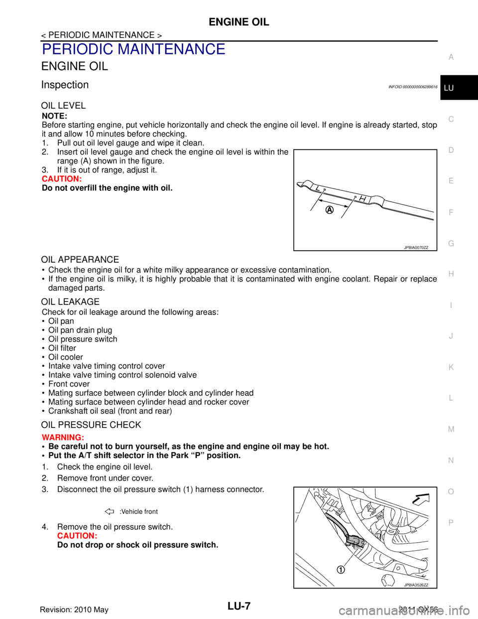
1. Pull out oil level gauge and wipe it clean.
2. Insert oil level gauge and check the engine oil level is within the range (A) shown in the figure.
3. If it is out of range, adjust it.
CAUTION:
Do not overfill the engine with oil.
OIL APPEARANCE
Check the engine oil for a white milky appearance or excessive contamination.
If the engine oil is milky, it is highly probable that it is contaminated with engine coolant. Repair or replace
damaged parts.
OIL LEAKAGE
Check for oil leakage around the following areas:
Oil pan
Oil pan drain plug
Oil pressure switch
Oil filter
Oil cooler
Intake valve timing control cover
Intake valve timing control solenoid valve
Front cover
Mating surface between cylinder block and cylinder head
Mating surface between cylinder head and rocker cover
Crankshaft oil seal (front and rear)
OIL PRESSURE CHECK
WARNING:
• Be careful not to burn yourself, as th e engine and engine oil may be hot.
Put the A/T shift selector in the Park “P” position.
1. Check the engine oil level.
2. Remove front under cover.
3. Disconnect the oil pressure switch (1) harness connector.
4. Remove the oil pressure switch. CAUTION:
Do not drop or shock oil pressure switch.
JPBIA0070ZZ
:Vehicle front
JPBIA3526ZZ
Revision: 2010 May2011 QX56
Page 3664 of 5598
OIL COOLERLU-11
< REMOVAL AND INSTALLATION >
C
DE
F
G H
I
J
K L
M A
LU
NP
O
REMOVAL AND INSTALLATION
OIL COOLER
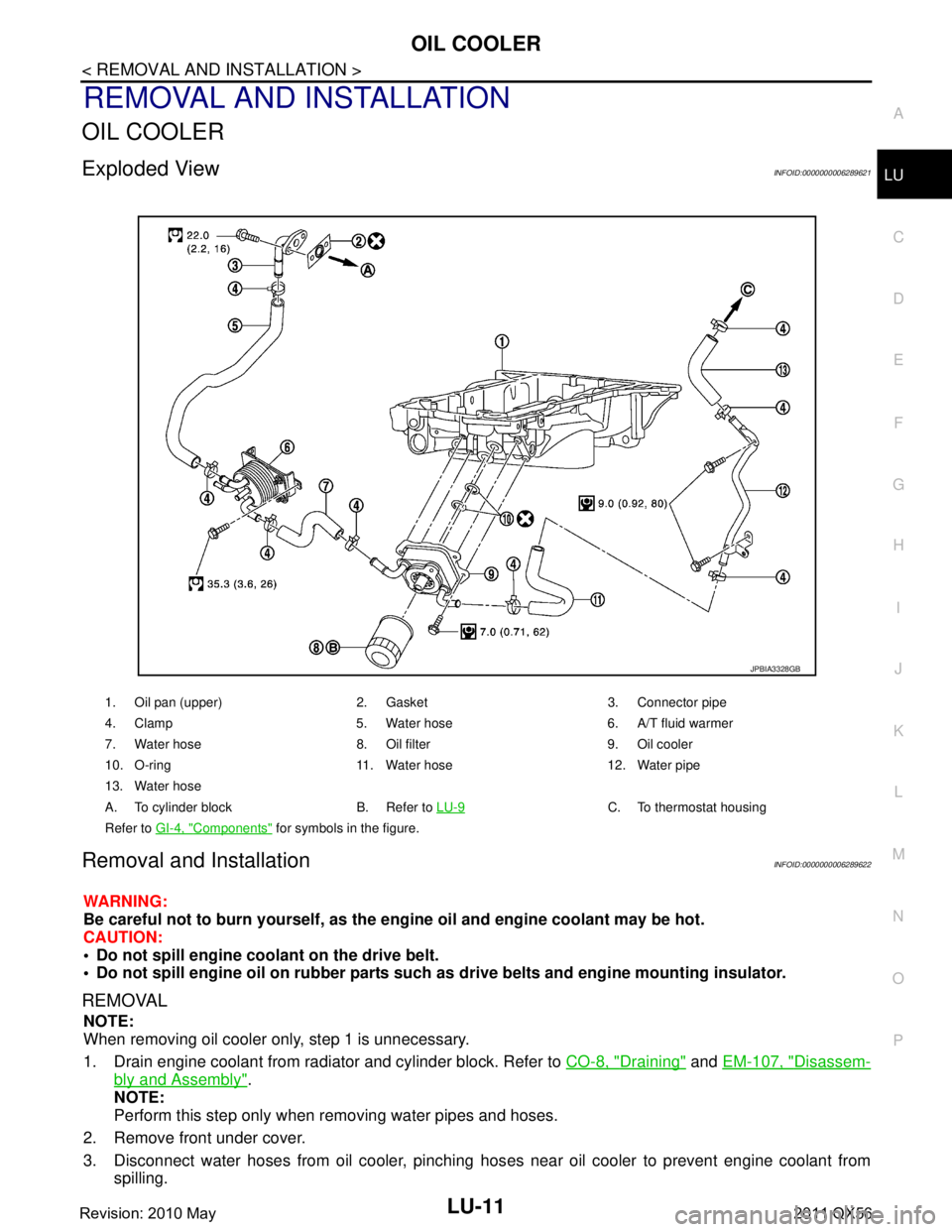
Exploded ViewINFOID:0000000006289621
Removal and InstallationINFOID:0000000006289622
WARNING:
Be careful not to burn yourself, as the en
gine oil and engine coolant may be hot.
CAUTION:
Do not spill engine coolant on the drive belt.
Do not spill engine oil on rubber parts such as drive belts and engine mounting insulator.
REMOVAL
NOTE:
When removing oil cooler only, step 1 is unnecessary.
1. Drain engine coolant from radiator and cylinder block. Refer to CO-8, "
Draining" and EM-107, "Disassem-
bly and Assembly".
NOTE:
Perform this step only when removing water pipes and hoses.
2. Remove front under cover.
3. Disconnect water hoses from oil cooler, pinching hos es near oil cooler to prevent engine coolant from
spilling.
1. Oil pan (upper) 2. Gasket 3. Connector pipe
4. Clamp 5. Water hose 6. A/T fluid warmer
7. Water hose 8. Oil filter 9. Oil cooler
10. O-ring 11. Water hose 12. Water pipe
13. Water hose
A. To cylinder block B. Refer to LU-9
C. To thermostat housing
Refer to GI-4, "
Components" for symbols in the figure.
JPBIA3328GB
Revision: 2010 May2011 QX56
Page 3665 of 5598
LU-12
< REMOVAL AND INSTALLATION >
OIL COOLER
CAUTION:
Perform this step when engine is cold.
4. Remove oil filter. Refer to LU-9, "
Removal and Installation".
5. Remove connector bolt, and remove oil cooler.
INSTALLATION
Installation is in the reverse order of removal, paying attention to the following:
Confirm that no foreign objects are adhering to the sealing surfaces of the oil cooler and oil pan.
InspectionINFOID:0000000006289623
INSPECTION AFTER REMOVAL
Oil Cooler
Check oil cooler for cracks. Check oil cooler for clogging by blowing compressed air through engine coolant
inlet. If necessary, replace oil cooler assembly.
Relief Valve
Inspect relief valve for movement, cracks and breaks by pushing the ball. If replacement is necessary, remove
the valve by prying it out using a suitable tool. Install a new valve in place by tapping it in.
INSPECTION AFTER INSTALLATION
1. Check engine oil and engine coolant levels and add engine oil and engine coolant. Refer to LU-7, "Inspec-
tion" and CO-8, "Inspection".
2. Start the engine, and check for l eaks of engine oil or engine coolant.
3. Stop the engine and wait for 10 minutes.
4. Check the engine oil level and engine coolant level again. Refer to LU-7, "
Inspection" and CO-8, "Inspec-
tion"
Revision: 2010 May2011 QX56
Page 3666 of 5598
OIL PUMPLU-13
< REMOVAL AND INSTALLATION >
C
DE
F
G H
I
J
K L
M A
LU
NP
O
OIL PUMP
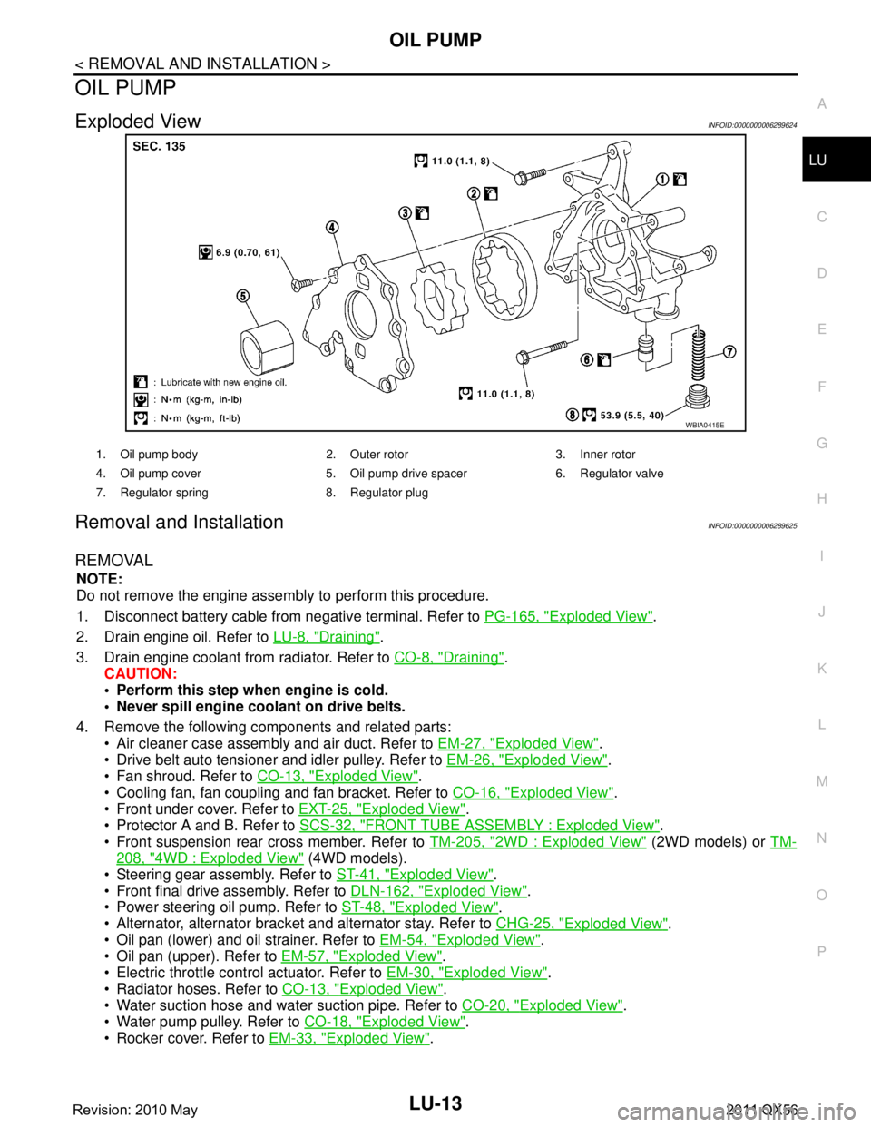
Exploded ViewINFOID:0000000006289624
Removal and InstallationINFOID:0000000006289625
REMOVAL
NOTE:
Do not remove the engine assembly to perform this procedure.
1. Disconnect battery cable from
negative terminal. Refer to PG-165, "
Exploded View".
2. Drain engine oil. Refer to LU-8, "
Draining".
3. Drain engine coolant from radiator. Refer to CO-8, "
Draining".
CAUTION:
Perform this step when engine is cold.
Never spill engine coolant on drive belts.
4. Remove the following components and related parts: Air cleaner case assembly and air duct. Refer to EM-27, "
Exploded View".
Drive belt auto tensioner and idler pulley. Refer to EM-26, "
Exploded View".
Fan shroud. Refer to CO-13, "
Exploded View".
Cooling fan, fan coupling and fan bracket. Refer to CO-16, "
Exploded View".
Front under cover. Refer to EXT-25, "
Exploded View".
Protector A and B. Refer to SCS-32, "
FRONT TUBE ASSEMBLY : Exploded View".
Front suspension rear cross member. Refer to TM-205, "
2WD : Exploded View" (2WD models) or TM-
208, "4WD : Exploded View" (4WD models).
Steering gear assembly. Refer to ST-41, "
Exploded View".
Front final drive assembly. Refer to DLN-162, "
Exploded View".
Power steering oil pump. Refer to ST-48, "
Exploded View".
Alternator, alternator bracket and alternator stay. Refer to CHG-25, "
Exploded View".
Oil pan (lower) and oil strainer. Refer to EM-54, "
Exploded View".
Oil pan (upper). Refer to EM-57, "
Exploded View".
Electric throttle control actuator. Refer to EM-30, "
Exploded View".
Radiator hoses. Refer to CO-13, "
Exploded View".
Water suction hose and water suction pipe. Refer to CO-20, "
Exploded View".
Water pump pulley. Refer to CO-18, "
Exploded View".
Rocker cover. Refer to EM-33, "
Exploded View".
WBIA0415E
1. Oil pump body 2. Outer rotor 3. Inner rotor
4. Oil pump cover 5. Oil pump drive spacer 6. Regulator valve
7. Regulator spring 8. Regulator plug
Revision: 2010 May2011 QX56
Page 3671 of 5598
MA-1
MAINTENANCE
C
DE
F
G H
I
J
K L
M B
MA
SECTION MA
N
O A
CONTENTS
MAINTENANCE
PREPARATION .............
...............................3
PREPARATION .............................................. .....3
Special Service Tool ........................................... ......3
Commercial Service Tool ..........................................3
PERIODIC MAINTENANCE ..........................4
GENERAL MAINTENANCE ........................... .....4
Explanation of General Maintenance .................. ......4
PERIODIC MAINTENANCE ................................6
Introduction of Periodic Maintenance .................. ......6
Schedule 1 ................................................................6
Schedule 2 ................................................................8
RECOMMENDED FLUIDS AND LUBRI-
CANTS ................................................................
10
Fluids and Lubricants .......................................... ....10
Engine Oil Recommendation ..................................10
Anti-Freeze Coolant Mixture Ratio ..........................11
ENGINE MAINTENANCE ...................................12
DRIVE BELTS ....................................................... ....12
DRIVE BELTS : Exploded View ..............................12
DRIVE BELTS : Checking .......................................12
DRIVE BELTS : Tension Adjustment .....................12
ENGINE COOLANT ............................................... ....12
ENGINE COOLANT : Inspection .............................12
ENGINE COOLANT : Draining ................................13
ENGINE COOLANT : Refilling ................................13
ENGINE COOLANT : Flushing ...............................15
RESERVOIR TANK CAP ..........................................15
RESERVOIR TANK CAP : Inspection ................. ....15
RADIATOR ............................................................ ....16
RADIATOR : Inspection ..........................................16
FUEL LINES .......................................................... ....16
FUEL LINES : Inspection ........................................17
AIR CLEANER FILTER ......................................... ....17
AIR CLEANER FILTER : Removal and Installation
....
17
ENGINE OIL ........................................................... ....17
ENGINE OIL : Draining ............................................17
ENGINE OIL : Refilling ............................................17
OIL FILTER ............................................................ ....18
OIL FILTER : Removal and Installation ...................18
SPARK PLUG ........................................................ ....18
SPARK PLUG : Removal and Installation ...............19
SPARK PLUG : Inspection ......................................19
EVAP VAPOR LINES ............................................ ....20
EVAP VAPOR LINES : Inspection ...........................20
CHASSIS MAINTENANCE ...............................21
EXHAUST SYSTEM . ..................................................21
EXHAUST SYSTEM : Inspec tion ............................21
A/T FLUID .............................................................. ....21
A/T FLUID : Inspection ............................................21
TRANSFER FLUID ................................................ ....21
TRANSFER FLUID : Inspection ..............................21
TRANSFER FLUID : Draining .................................21
TRANSFER FLUID : Refilling ..................................22
FRONT PROPELLER SHAFT: 2F P15 ................. ....22
FRONT PROPELLER SHAFT: 2F P15 : Inspec-
tion ...........................................................................
22
REAR PROPELLER SHAFT: 2F P26 .................... ....23
REAR PROPELLER SHAFT: 2F P26 : Inspection ....23
REAR PROPELLER SHAFT: 2S1410 ................... ....23
REAR PROPELLER SHAFT: 2S1410 : Inspection ....23
FRONT DIFFERENTIAL GEAR OIL: R180A ........ ....24
FRONT DIFFERENTIAL GEAR OIL: R180A : In-
spection ...................................................................
24
Revision: 2010 May2011 QX56
Page 3672 of 5598
MA-2
FRONT DIFFERENTIAL GEAR OIL: R180A :
Draining ..................................................................
24
FRONT DIFFERENTIAL GEAR OIL: R180A : Re-
filling .......................................................................
25
REAR DIFFERENTIAL GEAR OIL: R230 ............. ...25
REAR DIFFERENTIAL GEAR OIL: R230 : Inspec-
tion ..........................................................................
25
REAR DIFFERENTIAL GEAR OIL: R230 : Drain-
ing ...........................................................................
25
REAR DIFFERENTIAL GEAR OIL: R230 : Refill-
ing ...........................................................................
26
WHEELS (BONDING WEIGHT TYPE) .....................26
WHEELS (BONDING WEIGHT TYPE) : Adjust-
ment ..................................................................... ...
26
BRAKE FLUID LEVEL AND LEAKS ........................27
BRAKE FLUID LEVEL AND LEAKS : Inspection ...28
BRAKE LINES AND CABLES ............................... ...28
BRAKE LINES AND CABLES : Inspection .............28
BRAKE FLUID ....................................................... ...28
BRAKE FLUID : Bleeding Brake System ................28
DISC BRAKE ......................................................... ...30
DISC BRAKE : Inspection ......................................30
DISC BRAKE : Front Disc Brake ............................31
DISC BRAKE : Rear Disc Brake .............................31
STEERING GEAR AND LINKAGE ........................ ...31
STEERING GEAR AND LINKAGE : Inspection ......31
POWER STEERING FLUID AND LINES ............... ...32
POWER STEERING FLUID AND LINES : Inspec-
tion ..........................................................................
32
AXLE AND SUSPENSION PARTS ...........................32
AXLE AND SUSPENSION PARTS : Inspection .. ...32
DRIVE SHAFT ........................................................ ...33
DRIVE SHAFT : Inspection .....................................33
BODY MAINTENANCE .....................................34
LOCKS, HINGES AND HOOD LATCH .................. ...34
LOCKS, HINGES AND HOOD LATCH : Lubricat-
ing ...........................................................................
34
SEAT BELT, BUCKLES, RETRACTORS, AN-
CHORS AND ADJUSTERS ................................... ...
34
SEAT BELT, BUCKLES, RETRACTORS, AN-
CHORS AND ADJUSTERS : Inspection .................
34
SERVICE DATA AND SPECIFICATIONS
(SDS) .......... ................................................
35
SERVICE DATA AND SPECIFICATIONS
(SDS) .............................................................. ...
35
DRIVE BELTS ........................................................ ...35
DRIVE BELTS : Drive Belts ....................................35
ENGINE COOLANT ............................................... ...35
ENGINE COOLANT :
Periodical Maintenance Specification ....................
35
ENGINE OIL ........................................................... ...35
ENGINE OIL : Periodical Maintenance Specifica-
tion ..........................................................................
35
SPARK PLUG ........................................................ ...35
SPARK PLUG : Spark Plug ....................................35
ROAD WHEEL ....................................................... ...35
ROAD WHEEL : Road Wheel .................................35
Revision: 2010 May2011 QX56