2011 INFINITI QX56 wheel
[x] Cancel search: wheelPage 1437 of 5598
![INFINITI QX56 2011 Factory Service Manual
DAS-472
< DTC/CIRCUIT DIAGNOSIS >[BSW]
C1A03 VEHICLE SPEED SENSOR
C1A03 VEHICLE SPEED SENSOR
DTC LogicINFOID:0000000006223884
DTC DETECTION LOGIC
NOTE:
If DTC “C1A03” is detected along
with DTC INFINITI QX56 2011 Factory Service Manual
DAS-472
< DTC/CIRCUIT DIAGNOSIS >[BSW]
C1A03 VEHICLE SPEED SENSOR
C1A03 VEHICLE SPEED SENSOR
DTC LogicINFOID:0000000006223884
DTC DETECTION LOGIC
NOTE:
If DTC “C1A03” is detected along
with DTC](/manual-img/42/57033/w960_57033-1436.png)
DAS-472
< DTC/CIRCUIT DIAGNOSIS >[BSW]
C1A03 VEHICLE SPEED SENSOR
C1A03 VEHICLE SPEED SENSOR
DTC LogicINFOID:0000000006223884
DTC DETECTION LOGIC
NOTE:
If DTC “C1A03” is detected along
with DTC “U1000” or “C1A04”, first diagnose the DTC “U1000” or “C1A04”.
Refer to DAS-486, "
ADAS CONTROL UNIT : DTC Logic" for DTC “U1000”.
Refer to DAS-348, "
DTC Logic" for DTC “C1A04”.
DTC CONFIRMATION PROCEDURE
1.PERFORM DTC CONFIRMATION PROCEDURE
1. Start the engine.
2. Turn the BSW system ON.
3. Drive the vehicle at 30 km/h (19 MPH) or more. CAUTION:
Always drive safely.
4. Stop the vehicle.
5. Perform “All DTC Reading” with CONSULT-III.
6. Check if the “C1A03” is detected as the current malfunction in “Self Diagnostic Result” of “ICC/ADAS”.
Is
“C1A03” detected as the current malfunction?
YES-1 (BSW warning lamp: ON)>>Refer to DAS-472, "Diagnosis Procedure".
YES-2 (BSW warning lamp: OFF)>>Refer to CCS-87, "
Diagnosis Procedure".
NO >> Refer to GI-40, "
Intermittent Incident".
Diagnosis ProcedureINFOID:0000000006223885
1.CHECK SELF-DIAGNOSIS RESULTS
Check if “C1A04” or “U1000” is detected other than “C1A03” in “Self Diagnostic Result” of “ICC/ADAS”.
Is any DTC detected?
YES >> Perform diagnosis on the detected DTC and repair or replace the malfunctioning parts. Refer to
DAS-440, "
DTC Index".
NO >> GO TO 2.
2.CHECK ABS ACTUATOR AND ELECTRIC UNIT (CONTROL UNIT) SELF-DIAGNOSIS RESULTS
Check if any DTC is detected in “Self Diagnostic Result” of “ABS”.
Is any DTC detected?
YES >> Perform diagnosis on the detected DTC and repair or replace the malfunctioning parts. Refer to
BRC-51, "
DTC Index".
NO >> Replace the ADAS control unit. Refer to DAS-63, "
Removal and Installation".
DTC
(On board
display) Trouble diagnosis
name DTC detecting condition Possible causes
C1A03 (3) VHCL SPEED SE
CIRC If the vehicle speed signal (wheel speed) from
ABS actuator and electric
unit (control unit) re-
ceived by the ADAS control unit via CAN com-
munication, are inconsistent Wheel speed sensor
ABS actuator and electric unit (control
unit)
ADAS control unit
Revision: 2010 May2011 QX56
Page 1493 of 5598
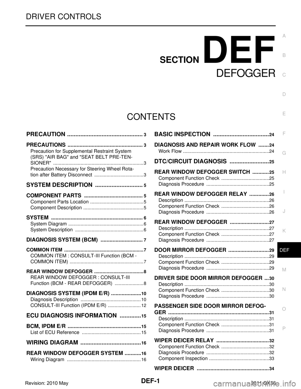
DEF-1
DRIVER CONTROLS
C
DE
F
G H
I
J
K
M
SECTION DEF
A
B
DEF
N
O P
CONTENTS
DEFOGGER
PRECAUTION ................ ...............................3
PRECAUTIONS .............................................. .....3
Precaution for Supplemental Restraint System
(SRS) "AIR BAG" and "SEAT BELT PRE-TEN-
SIONER" ............................................................. ......
3
Precaution Necessary for Steering Wheel Rota-
tion after Battery Disconnect .....................................
3
SYSTEM DESCRIPTION ..............................5
COMPONENT PARTS ................................... .....5
Component Parts Location .................................. ......5
Component Description .............................................5
SYSTEM ..............................................................6
System Diagram .................................................. ......6
System Description ...................................................6
DIAGNOSIS SYSTEM (BCM) .............................7
COMMON ITEM ..................................................... ......7
COMMON ITEM : CONSULT-III Function (BCM -
COMMON ITEM) .......................................................
7
REAR WINDOW DEFOGGER ............................... ......8
REAR WINDOW DEFOGGER : CONSULT-III
Function (BCM - REAR DEFOGGER) ......................
8
DIAGNOSIS SYSTEM (IPDM E/R) .....................10
Diagnosis Description ......................................... ....10
CONSULT-III Function (IPDM E/R) .........................12
ECU DIAGNOSIS INFORMATION ..............15
BCM, IPDM E/R .............................................. ....15
List of ECU Reference ........................................ ....15
WIRING DIAGRAM ......................................16
REAR WINDOW DEFOGGER SYSTEM ........ ....16
Wiring Diagram ................................................... ....16
BASIC INSPECTION ...................................24
DIAGNOSIS AND REPAIR WORK FLOW .......24
Work Flow ............................................................ ....24
DTC/CIRCUIT DIAGNOSIS .........................25
REAR WINDOW DEFOGGER SWITCH ...........25
Component Function Check ................................ ....25
Diagnosis Procedure ...............................................25
REAR WINDOW DEFOGGER RELAY .............26
Description ...............................................................26
Component Function Check ....................................26
Diagnosis Procedure ...............................................26
REAR WINDOW DEFOGGER ..........................27
Description ...............................................................27
Component Function Check ....................................27
Diagnosis Procedure ...............................................27
DOOR MIRROR DEFOGGER ...........................29
Description ...............................................................29
Component Function Check ....................................29
Diagnosis Procedure ...............................................29
DRIVER SIDE DOOR MIRROR DEFOGGER ...30
Description ...............................................................30
Component Function Check ....................................30
Diagnosis Procedure ...............................................30
PASSENGER SIDE DOOR MIRROR DEFOG-
GER ...................................................................
31
Description ...............................................................31
Component Function Check ....................................31
Diagnosis Procedure ...............................................31
WIPER DEICER RELAY ...................................32
Component Function Check ....................................32
Diagnosis Procedure ...............................................32
Component Inspection .............................................33
WIPER DEICER ................................................34
Revision: 2010 May2011 QX56
Page 1495 of 5598
PRECAUTIONSDEF-3
< PRECAUTION >
C
DE
F
G H
I
J
K
M A
B
DEF
N
O P
PRECAUTION
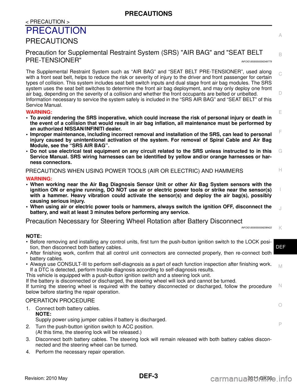
PRECAUTIONS
Precaution for Supplemental Restraint System (SRS) "AIR BAG" and "SEAT BELT
PRE-TENSIONER"
INFOID:0000000006349779
The Supplemental Restraint System such as “A IR BAG” and “SEAT BELT PRE-TENSIONER”, used along
with a front seat belt, helps to reduce the risk or severi ty of injury to the driver and front passenger for certain
types of collision. This system includes seat belt switch inputs and dual stage front air bag modules. The SRS
system uses the seat belt switches to determine the front air bag deployment, and may only deploy one front
air bag, depending on the severity of a collision and whether the front occupants are belted or unbelted.
Information necessary to service the system safely is included in the “SRS AIR BAG” and “SEAT BELT” of this
Service Manual.
WARNING:
• To avoid rendering the SRS inoper ative, which could increase the risk of personal injury or death in
the event of a collision that would result in air ba g inflation, all maintenance must be performed by
an authorized NISSAN/INFINITI dealer.
Improper maintenance, including in correct removal and installation of the SRS, can lead to personal
injury caused by unintentional act ivation of the system. For removal of Spiral Cable and Air Bag
Module, see the “SRS AIR BAG”.
Do not use electrical test equipm ent on any circuit related to the SRS unless instructed to in this
Service Manual. SRS wiring harnesses can be identi fied by yellow and/or orange harnesses or har-
ness connectors.
PRECAUTIONS WHEN USING POWER TOOLS (AIR OR ELECTRIC) AND HAMMERS
WARNING:
When working near the Air Bag Diagnosis Sensor Unit or other Air Bag System sensors with the
ignition ON or engine running, DO NOT use air or electric power tools or strike near the sensor(s)
with a hammer. Heavy vibration could activate the sensor(s) and deploy the air bag(s), possibly
causing serious injury.
When using air or electric power tools or hammers , always switch the ignition OFF, disconnect the
battery, and wait at least 3 minutes before performing any service.
Precaution Necessary for Steering Wh eel Rotation after Battery Disconnect
INFOID:0000000006299422
NOTE:
Before removing and installing any control units, first tu rn the push-button ignition switch to the LOCK posi-
tion, then disconnect both battery cables.
After finishing work, confirm that all control unit connectors are connected properly, then re-connect both
battery cables.
Always use CONSULT-III to perform self-diagnosis as a part of each function inspection after finishing work.
If a DTC is detected, perform trouble diagnos is according to self-diagnosis results.
This vehicle is equipped with a push-button ignition switch and a steering lock unit.
If the battery is disconnect ed or discharged, the steering wheel will lock and cannot be turned.
If turning the steering wheel is required with the battery disconnected or discharged, follow the procedure
below before starting the repair operation.
OPERATION PROCEDURE
1. Connect both battery cables. NOTE:
Supply power using jumper cables if battery is discharged.
2. Turn the push-button ignition switch to ACC position. (At this time, the steering lock will be released.)
3. Disconnect both battery cables. The steering lock wil l remain released with both battery cables discon-
nected and the steering wheel can be turned.
4. Perform the necessary repair operation.
Revision: 2010 May2011 QX56
Page 1496 of 5598

DEF-4
< PRECAUTION >
PRECAUTIONS
5. When the repair work is completed, re-connect both battery cables. With the brake pedal released, turn
the push-button ignition switch from ACC position to ON position, then to LOCK position. (The steering
wheel will lock when the push-button igniti on switch is turned to LOCK position.)
6. Perform self-diagnosis check of all control units using CONSULT-III.
Revision: 2010 May2011 QX56
Page 1537 of 5598
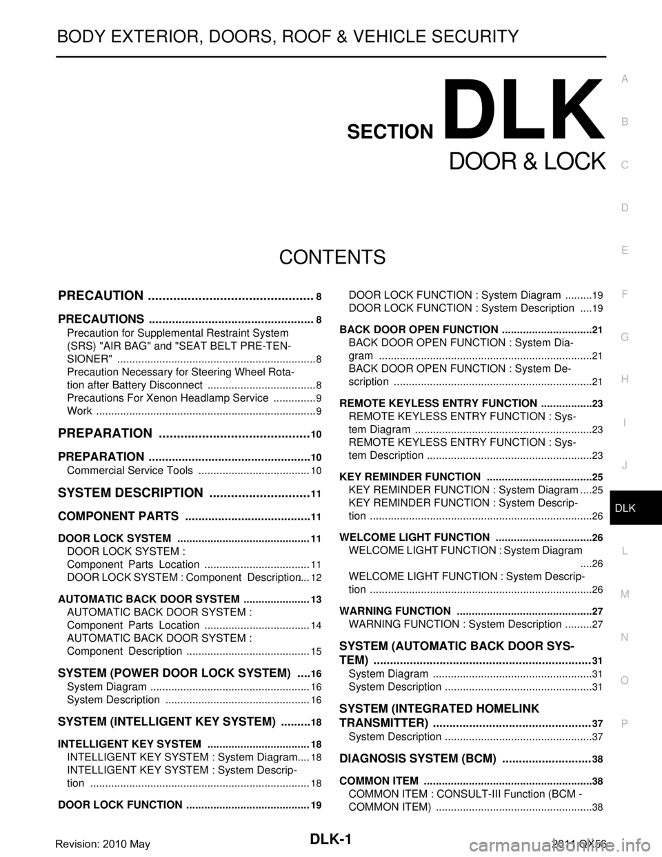
DLK-1
BODY EXTERIOR, DOORS, ROOF & VEHICLE SECURITY
C
D
E
F
G H
I
J
L
M
SECTION DLK
A
B
DLK
N
O P
CONTENTS
DOOR & LOCK
PRECAUTION ................ ...............................8
PRECAUTIONS .............................................. .....8
Precaution for Supplemental Restraint System
(SRS) "AIR BAG" and "SEAT BELT PRE-TEN-
SIONER" ............................................................. ......
8
Precaution Necessary for Steering Wheel Rota-
tion after Battery Disconnect .....................................
8
Precautions For Xenon Headlamp Service ...............9
Work ..........................................................................9
PREPARATION ...........................................10
PREPARATION .............................................. ....10
Commercial Service Tools .................................. ....10
SYSTEM DESCRIPTION .............................11
COMPONENT PARTS ................................... ....11
DOOR LOCK SYSTEM .............................................11
DOOR LOCK SYSTEM :
Component Parts Location ................................ ....
11
DOOR LOCK SYSTEM : Component Description ....12
AUTOMATIC BACK DOOR SYSTEM .......................13
AUTOMATIC BACK DOOR SYSTEM :
Component Parts Location ................................ ....
14
AUTOMATIC BACK DOOR SYSTEM :
Component Description ..........................................
15
SYSTEM (POWER DOOR LOCK SYSTEM) .....16
System Diagram .................................................. ....16
System Description .................................................16
SYSTEM (INTELLIGENT KEY SYSTEM) ..........18
INTELLIGENT KEY SYSTEM ...................................18
INTELLIGENT KEY SYSTEM : System Diagram ....18
INTELLIGENT KEY SYSTEM : System Descrip-
tion ..........................................................................
18
DOOR LOCK FUNCTION ...................................... ....19
DOOR LOCK FUNCTION : System Diagram ..........19
DOOR LOCK FUNCTION : System Description .....19
BACK DOOR OPEN FUNCTION ........................... ....21
BACK DOOR OPEN FUNCTION : System Dia-
gram ........................................................................
21
BACK DOOR OPEN FUNCTION : System De-
scription ...................................................................
21
REMOTE KEYLESS ENTRY FUNCTION ..................23
REMOTE KEYLESS ENTRY FUNCTION : Sys-
tem Diagram ........................................................ ....
23
REMOTE KEYLESS ENTRY FUNCTION : Sys-
tem Description ........................................................
23
KEY REMINDER FUNCTION ................................ ....25
KEY REMINDER FUNCTION : System Diagram ....25
KEY REMINDER FUNCTION : System Descrip-
tion ...........................................................................
26
WELCOME LIGHT FUNCTION ............................. ....26
WELCOME LIGHT FUNCTION : System Diagram
....
26
WELCOME LIGHT FUNCTION : System Descrip-
tion ...........................................................................
26
WARNING FUNCTION .......................................... ....27
WARNING FUNCTION : System Description ..........27
SYSTEM (AUTOMATIC BACK DOOR SYS-
TEM) ..................................................................
31
System Diagram .................................................. ....31
System Description ..................................................31
SYSTEM (INTEGRATED HOMELINK
TRANSMITTER) ................................................
37
System Description .............................................. ....37
DIAGNOSIS SYSTEM (BCM) ...........................38
COMMON ITEM ..................................................... ....38
COMMON ITEM : CONSULT-III Function (BCM -
COMMON ITEM) .....................................................
38
Revision: 2010 May2011 QX56
Page 1544 of 5598
DLK-8
< PRECAUTION >
PRECAUTIONS
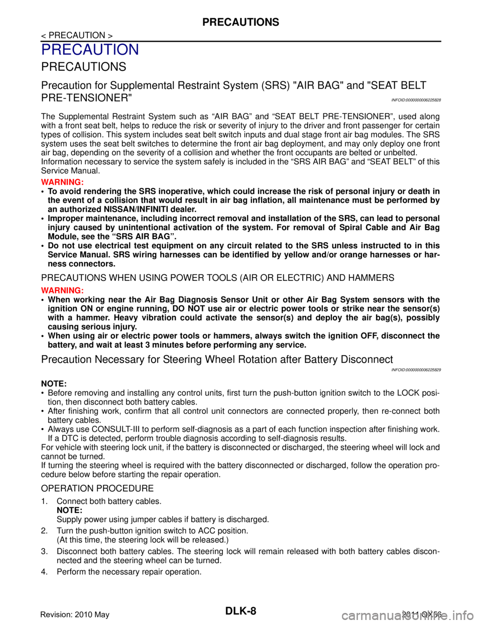
PRECAUTION
PRECAUTIONS
Precaution for Supplemental Restraint System (SRS) "AIR BAG" and "SEAT BELT
PRE-TENSIONER"
INFOID:0000000006225828
The Supplemental Restraint System such as “A IR BAG” and “SEAT BELT PRE-TENSIONER”, used along
with a front seat belt, helps to reduce the risk or severi ty of injury to the driver and front passenger for certain
types of collision. This system includes seat belt switch inputs and dual stage front air bag modules. The SRS
system uses the seat belt switches to determine the front air bag deployment, and may only deploy one front
air bag, depending on the severity of a collision and w hether the front occupants are belted or unbelted.
Information necessary to service the system safely is included in the “SRS AIR BAG” and “SEAT BELT” of this
Service Manual.
WARNING:
• To avoid rendering the SRS inopera tive, which could increase the risk of personal injury or death in
the event of a collision that would result in air bag inflation, all maintenance must be performed by
an authorized NISS AN/INFINITI dealer.
Improper maintenance, including in correct removal and installation of the SRS, can lead to personal
injury caused by unintent ional activation of the system. For re moval of Spiral Cable and Air Bag
Module, see the “SRS AIR BAG”.
Do not use electrical test equipmen t on any circuit related to the SRS unless instructed to in this
Service Manual. SRS wiring harnesses can be identi fied by yellow and/or orange harnesses or har-
ness connectors.
PRECAUTIONS WHEN USING POWER TOOLS (AIR OR ELECTRIC) AND HAMMERS
WARNING:
When working near the Air Bag Diagnosis Sensor Unit or other Air Bag System sensors with the ignition ON or engine running, DO NOT use air or electric power tools or strike near the sensor(s)
with a hammer. Heavy vibration could activate the sensor(s) and deploy the air bag(s), possibly
causing serious injury.
When using air or electric power tools or hammers , always switch the ignition OFF, disconnect the
battery, and wait at least 3 minu tes before performing any service.
Precaution Necessary for Steering W heel Rotation after Battery Disconnect
INFOID:0000000006225829
NOTE:
Before removing and installing any control units, first tu rn the push-button ignition switch to the LOCK posi-
tion, then disconnect bot h battery cables.
After finishing work, confirm that all control unit connectors are connected properly, then re-connect both
battery cables.
Always use CONSULT-III to perform self-diagnosis as a part of each function inspection after finishing work.
If a DTC is detected, perform trouble diagnos is according to self-diagnosis results.
For vehicle with steering lock unit, if the battery is disconnected or discharged, the steering wheel will lock and
cannot be turned.
If turning the steering wheel is required with the bat tery disconnected or discharged, follow the operation pro-
cedure below before starting the repair operation.
OPERATION PROCEDURE
1. Connect both battery cables. NOTE:
Supply power using jumper cables if battery is discharged.
2. Turn the push-button ignition switch to ACC position. (At this time, the steering lock will be released.)
3. Disconnect both battery cables. The steering lock wi ll remain released with both battery cables discon-
nected and the steering wheel can be turned.
4. Perform the necessary repair operation.
Revision: 2010 May2011 QX56
Page 1545 of 5598
PRECAUTIONSDLK-9
< PRECAUTION >
C
DE
F
G H
I
J
L
M A
B
DLK
N
O P
5. When the repair work is completed, re-connect both battery cables. With the brake pedal released, turn
the push-button ignition switch from ACC position to ON position, then to LOCK position. (The steering
wheel will lock when the push-button ignition switch is turned to LOCK position.)
6. Perform self-diagnosis check of a ll control units using CONSULT-III.
Precautions For Xenon Headlamp ServiceINFOID:0000000006225830
WARNING:
Comply with the follow ing warnings to prevent any serious accident.
Disconnect the battery cable (neg ative terminal) or the power supply fuse before installing, remov-
ing, or touching the xenon headlamp (bulb included). The xenon headlamp contains high-voltage
generated parts.
Never work with wet hands.
Check the xenon headlamp ON-OFF status after assem bling it to the vehicle. Never turn the xenon
headlamp ON in other conditions. Connect th e power supply to the vehicle-side connector.
(Turning it ON outside the lamp case m ay cause fire or visual impairments.)
Never touch the bulb glass immediately afte r turning it OFF. It is extremely hot.
CAUTION:
Comply with the follow ing cautions to prevent an y error and malfunction.
Install the xenon bulb securely. (I nsufficient bulb socket installation may melt the bulb, the connec-
tor, the housing, etc. by high-vol tage leakage or corona discharge.)
Never perform HID circuit inspection with a tester.
Never touch the xenon bulb glass with ha nds. Never put oil and grease on it.
Dispose of the used xenon bulb after p acking it in thick vinyl without breaking it.
Never wipe out dirt and cont amination with organic solven t (thinner, gasoline, etc.).
WorkINFOID:0000000006225831
After removing and installing the opening/closing parts, be sure to carry out fitting adjustments to check their
operational.
Check the lubrication level, damage, and wear of each part. If necessary, grease or replace it.
Revision: 2010 May2011 QX56
Page 1788 of 5598
DLK-252
< REMOVAL AND INSTALLATION >
CAB MOUNTING INSULATOR
Drain brake fluid from brake line. Refer to BR-10, "Draining".
Release fuel pressure. Refer to EC-153, "
Work Procedure".
Disconnect both battery cables. Refer to PG-164, "
Removal and Installation".
Drain engine coolant from radiator. Refer to CO-8, "
Draining".
Discharge refrigerant from A/C circuit. Refer to HA-20, "
Recycle Refrigerant".
Drain power steering fluid from reservoir tank.
4. Remove parts relating to connection of body assembly and frame assembly. Tire and wheel: Refer to WT-64, "
Removal and Installation" (with TPMS).
Front fender protector (LH and RH): Refer to EXT-23, "
FENDER PROTECTOR : Removal and Installa-
tion".
Front bumper: Refer to EXT-13, "
Removal and Installation".
Radiator core support upper: Refer to DLK-220, "
Removal and Installation".
Fan shroud: Refer to CO-16, "
Removal and Installation".
Battery and battery case: Refer to PG-164, "
Removal and Installation".
Air cleaner case (upper and lower): Refer to EM-27, "
Removal and Installation".
Engine cover: Refer to EM-25, "
Removal and Installation".
Rear wheel house protector (LH and RH): EXT-24, "
REAR WHEEL HOUSE PROTECTOR : Removal
and Installation".
Rear bumper: Refer to EXT-17, "
Removal and Installation".
Fuel filler tube: Remove to FL-8, "
Exploded View".
Spare tire
Towing hook bracket.
5. Separate parts relating to connection of body assembly and frame assembly. Vehicle front
Disconnect ICC sensor connector. (models with ICC) Refer to CCS-176, "
Removal and Installation".
Remove radiator upper hose and radiator lower hose from radiator assembly. Refer to CO-13,
"Exploded View".
Remove A/T fluid cooler hose B and A/T fluid cooler hose E from A/T fluid cooler tubes. Refer to TM-
202, "Exploded View".
Remove power steering return hose from oil cooler, and then power steering return hose clamp bolt from frame assembly. Refer to ST-54, "
Exploded View".
Remove power steering suction hose from reservoir tank. Refer to ST-54, "
Exploded View".
CAUTION:
Never spill power steering fluid in engine room.
Remove A/C low-presser flexible hose from A/C low-presser pipe. Refer to HA-35, "
LOW-PRESSURE
FLEXIBLE HOSE : Removal and Installation".
Remove A/C hi-presser flexible hose from condenser. Refer to HA-34, "
HIGH-PRESSURE FLEXIBLE
HOSE : Removal and Installation".
Remove all engine Control Harness connectors, har ness clips and others that are connected to the
body assembly side of the engine room. (engine room LH and RH side). Refer to PG-148, "
Engine Con-
trol Harness".
NOTE:
Separate harness connectors from ECM (engine control module). Refer to EC-10, "
General Precau-
tions".
CAUTION:
When pulling out harnesses, never damage harnesses or connectors.
After temporarily securing connectors, cover th em with vinyl or similar material to protect
against adhesion of foreign materials.
Disconnect engine room harness connectors and remo ve harness clips from engine assembly (engine
RH side). Refer to PG-146, "
Engine Room Harness".
Remove heater hoses from front water outlet tube (engine room RH side). Refer to HA-33, "
Exploded
View".
Disconnect front wheel sensor connectors (LH and RH). Refer to BRC-134, "
FRONT WHEEL SENSOR
: Exploded View".
Disconnect fuel feed tube and EVAP hos e (front wheel well LH side).
Remove steering lower shaft from steering gear side assembly. Refer to ST-37, "
Removal and Installa-
tion"
CAUTION:
Spiral cable may be cut if steering wheel turns while separating steering column assembly and
steering gear assembly.
Revision: 2010 May2011 QX56