2011 INFINITI QX56 ignition
[x] Cancel search: ignitionPage 3727 of 5598

MIR-22
< DTC/CIRCUIT DIAGNOSIS >
DOOR MIRROR REMOTE CONTROL SWITCH
DTC/CIRCUIT DIAGNOSIS
DOOR MIRROR REMOTE CONTROL SWITCH
OPEN/CLOSE SWITCH
OPEN/CLOSE SWITCH : Co mponent InspectionINFOID:0000000006257229
1.CHECK OPEN/CLOSE SWITCH
1. Turn ignition switch OFF.
2. Disconnect door mirror remote control switch connector.
3. Check continuity between door mirro r remote control switch terminals.
[Driver side]
[Passenger side]
Is the inspection result normal?
YES >> INSPECTION END
NO >> Replace door mirror remote control switch.
Door mirror remote control switch
Condition Continuity
Te r m i n a l
12 10
Open/close switchOPEN
Existed
13 8
12 8
CLOSE
13 10
Door mirror remote control switch Condition Continuity
Te r m i n a l
12 11
Open/close switchOPEN
Existed
13 9
12 9
CLOSE
13 11
Revision: 2010 May2011 QX56
Page 3747 of 5598

MWI-4
< PRECAUTION >
PRECAUTIONS
PRECAUTION
PRECAUTIONS
Precaution for Supplemental Restraint System (SRS) "AIR BAG" and "SEAT BELT
PRE-TENSIONER"
INFOID:0000000006369687
The Supplemental Restraint System such as “A IR BAG” and “SEAT BELT PRE-TENSIONER”, used along
with a front seat belt, helps to reduce the risk or severi ty of injury to the driver and front passenger for certain
types of collision. This system includes seat belt switch inputs and dual stage front air bag modules. The SRS
system uses the seat belt switches to determine the front air bag deployment, and may only deploy one front
air bag, depending on the severity of a collision and w hether the front occupants are belted or unbelted.
Information necessary to service the system safely is included in the “SRS AIR BAG” and “SEAT BELT” of this
Service Manual.
WARNING:
• To avoid rendering the SRS inopera tive, which could increase the risk of personal injury or death in
the event of a collision that would result in air bag inflation, all maintenance must be performed by
an authorized NISS AN/INFINITI dealer.
Improper maintenance, including in correct removal and installation of the SRS, can lead to personal
injury caused by unintent ional activation of the system. For re moval of Spiral Cable and Air Bag
Module, see the “SRS AIR BAG”.
Do not use electrical test equipmen t on any circuit related to the SRS unless instructed to in this
Service Manual. SRS wiring harnesses can be identi fied by yellow and/or orange harnesses or har-
ness connectors.
PRECAUTIONS WHEN USING POWER TOOLS (AIR OR ELECTRIC) AND HAMMERS
WARNING:
When working near the Air Bag Diagnosis Sensor Unit or other Air Bag System sensors with the ignition ON or engine running, DO NOT use air or electric power tools or strike near the sensor(s)
with a hammer. Heavy vibration could activate the sensor(s) and deploy the air bag(s), possibly
causing serious injury.
When using air or electric power tools or hammers , always switch the ignition OFF, disconnect the
battery, and wait at least 3 minu tes before performing any service.
Revision: 2010 May2011 QX56
Page 3753 of 5598
MWI-10
< SYSTEM DESCRIPTION >
SYSTEM
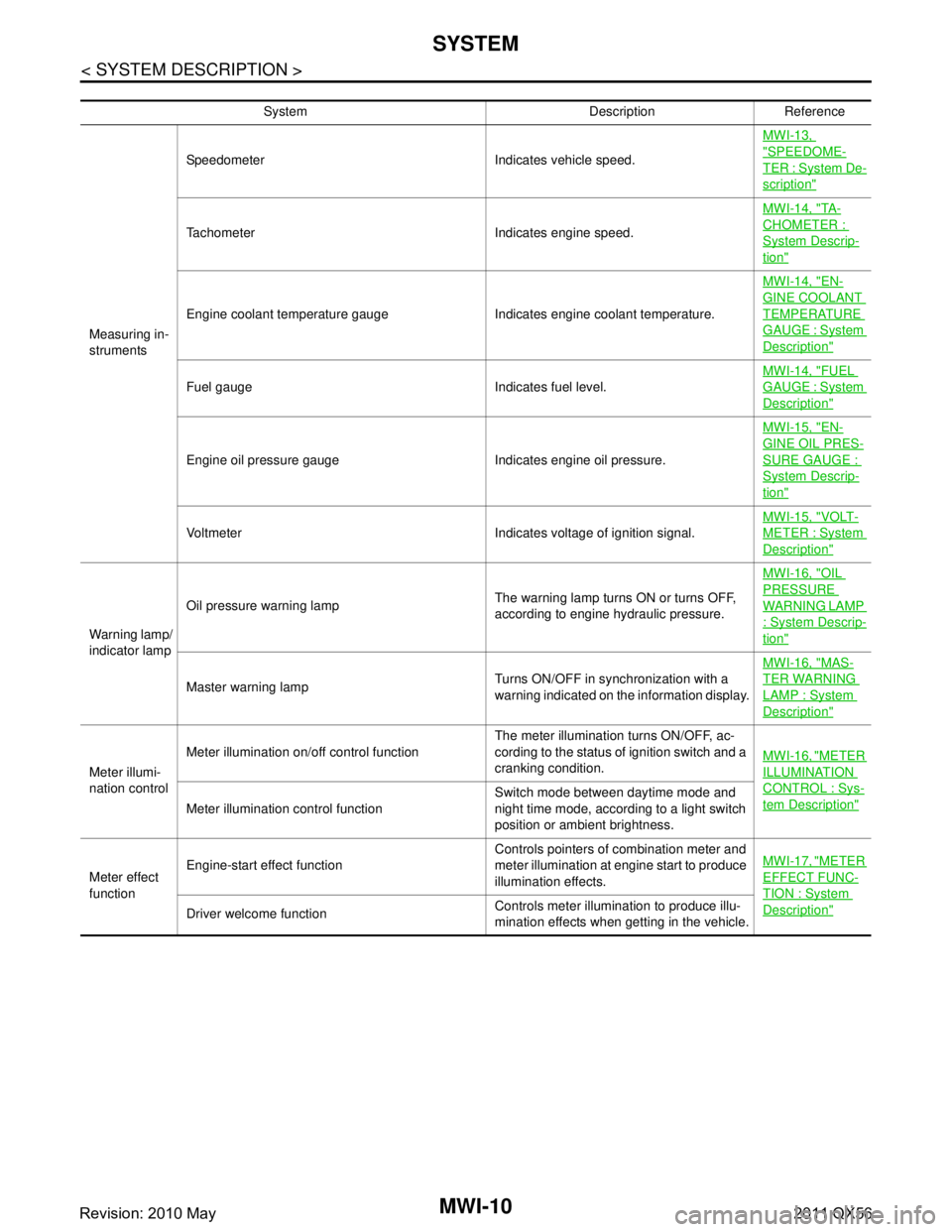
System Description Reference
Measuring in-
struments Speedometer Indicates vehicle speed.
MWI-13,
"SPEEDOME-
TER : System De-
scription"
Tachometer Indicates engine speed.MWI-14, "
TA -
CHOMETER :
System Descrip-
tion"
Engine coolant temperature gauge Indicates engine coolant temperature.MWI-14, "
EN-
GINE COOLANT
TEMPERATURE
GAUGE : System
Description"
Fuel gauge Indicates fuel level.
MWI-14, "
FUEL
GAUGE : System
Description"
Engine oil pressure gauge Indicates engine oil pressure.MWI-15, "
EN-
GINE OIL PRES-
SURE GAUGE :
System Descrip-
tion"
Voltmeter Indicates voltage of ignition signal.
MWI-15, "
VOLT-
METER : System
Description"
Warning lamp/
indicator lampOil pressure warning lamp
The warning lamp turns ON or turns OFF,
according to engine hydraulic pressure.MWI-16, "
OIL
PRESSURE
WARNING LAMP
: System Descrip-
tion"
Master warning lamp
Turns ON/OFF in synchronization with a
warning indicated on the information display.MWI-16, "
MAS-
TER WARNING
LAMP : System
Description"
Meter illumi-
nation controlMeter illumination on/off control function
The meter illumination turns ON/OFF, ac-
cording to the status of ignition switch and a
cranking condition.
MWI-16, "
METER
ILLUMINATION
CONTROL : Sys-
tem Description"Meter illumination control function Switch mode between daytime mode and
night time mode, according to a light switch
position or ambient brightness.
Meter effect
function Engine-start effect function
Controls pointers of combination meter and
meter illumination at engine start to produce
illumination effects.MWI-17, "
METER
EFFECT FUNC-
TION : System
Description"Driver welcome function
Controls meter illumination to produce illu-
mination effects when getting in the vehicle.
Revision: 2010 May2011 QX56
Page 3758 of 5598
MWI
SYSTEMMWI-15
< SYSTEM DESCRIPTION >
C
DE
F
G H
I
J
K L
M B A
O P
REFUEL CONTROL
The combination meter accelerates the fuel gauge if the all conditions listed below are met, or the ignition
switch is ON from OFF.
Ignition switch is ON position.
The vehicle is not moving.
The fuel level change by 15 (4 US gal, 3-1/4 Imp gal) or more.
ENGINE OIL PRESSURE GAUGE
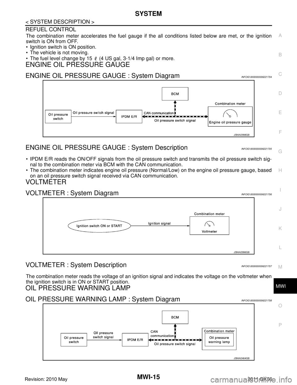
ENGINE OIL PRESSURE GAUGE : System DiagramINFOID:0000000006221704
ENGINE OIL PRESSURE GAUGE : System DescriptionINFOID:0000000006221705
IPDM E/R reads the ON/OFF signals from the oil pressure switch and transmits the oil pressure switch sig-
nal to the combination meter via BCM with the CAN communication.
The combination meter indicates engine oil pressure (Normal/Low) on the engine oil pressure gauge, based
on an oil pressure switch signal received via CAN communication.
VOLTMETER
VOLTMETER : System DiagramINFOID:0000000006221706
VOLTMETER : System DescriptionINFOID:0000000006221707
The combination meter reads the voltage of an ignition signal and indicates the voltage on the voltmeter when
the ignition switch is in ON or START position.
OIL PRESSURE WARNING LAMP
OIL PRESSURE WARNING LAMP : System DiagramINFOID:0000000006221708
JSNIA2998GB
JSNIA2996GB
JSNIA2464GB
Revision: 2010 May2011 QX56
Page 3759 of 5598
MWI-16
< SYSTEM DESCRIPTION >
SYSTEM
OIL PRESSURE WARNING LAMP : System Description
INFOID:0000000006221709
IPDM E/R reads the ON/OFF signals fr om the oil pressure switch and transmits the oil pressure switch sig-
nal to the combination meter via BCM with the CAN communication.
The combination meter turns the oil pressure warning lamp ON (at the time of a reduction in hydraulic pres-
sure)/OFF (except at the time of a reduction in hydraulic pressure) according to the oil pressure switch signal
received via CAN communication.
MASTER WARNING LAMP
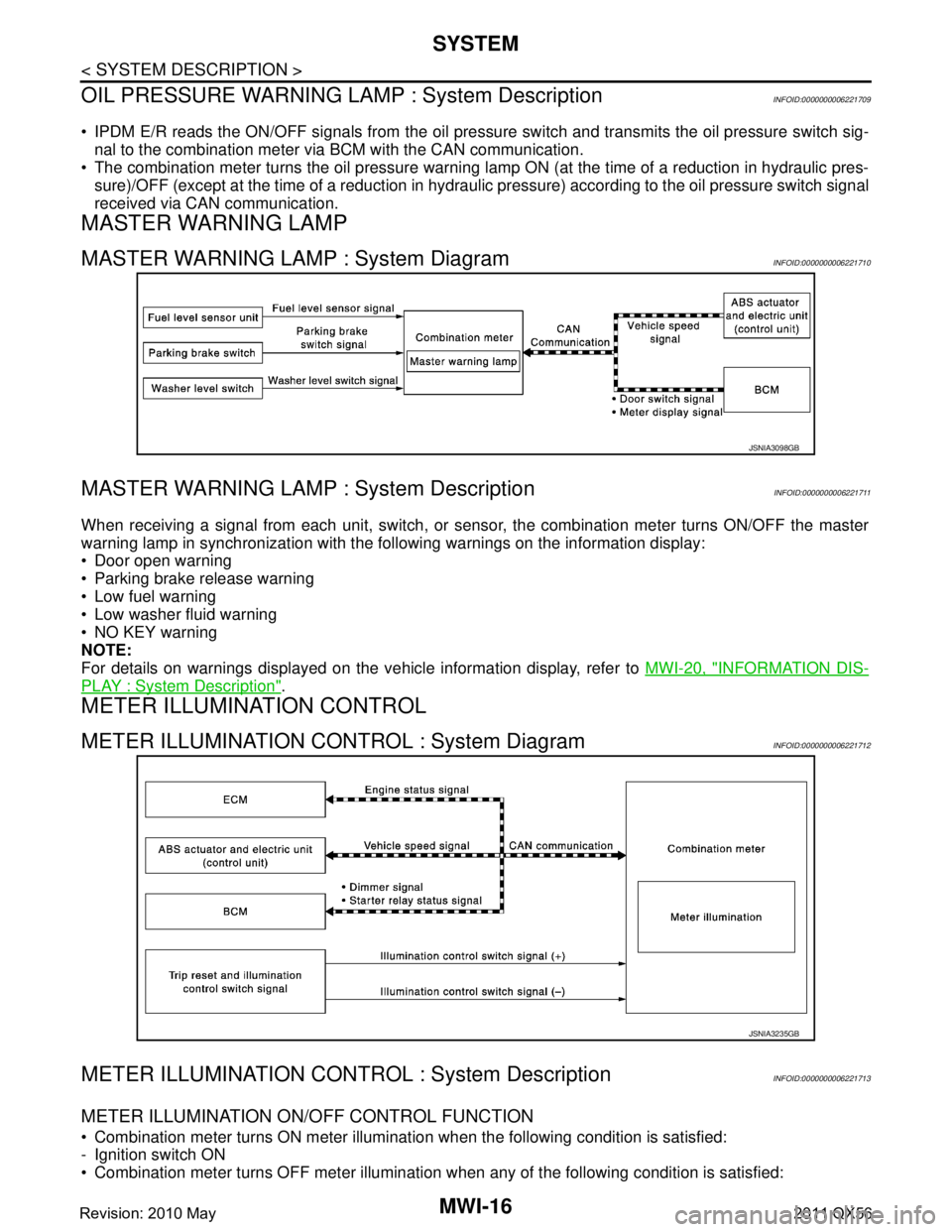
MASTER WARNING LAMP : System DiagramINFOID:0000000006221710
MASTER WARNING LAMP : System DescriptionINFOID:0000000006221711
When receiving a signal from each unit, switch, or s ensor, the combination meter turns ON/OFF the master
warning lamp in synchronization with the following warnings on the information display:
Door open warning
Parking brake release warning
Low fuel warning
Low washer fluid warning
NO KEY warning
NOTE:
For details on warnings displayed on the vehicle information display, refer to MWI-20, "
INFORMATION DIS-
PLAY : System Description".
METER ILLUMINATION CONTROL
METER ILLUMINATION CONTROL : System DiagramINFOID:0000000006221712
METER ILLUMINATION CONTRO L : System DescriptionINFOID:0000000006221713
METER ILLUMINATION ON/OFF CONTROL FUNCTION
Combination meter turns ON meter illumination when the following condition is satisfied:
- Ignition switch ON
Combination meter turns OFF meter illumination when any of the following condition is satisfied:
JSNIA3098GB
JSNIA3235GB
Revision: 2010 May2011 QX56
Page 3760 of 5598
MWI
SYSTEMMWI-17
< SYSTEM DESCRIPTION >
C
DE
F
G H
I
J
K L
M B A
O P
- During a crank with vehicle speed less than 1 km/h (0.6 MPH)
- Ignition switch OFF or ACC
The combination meter receives the following signals to control meter illumination.
METER ILLUMINATION CONTROL FUNCTION
The combination meter controls meter illumination, based on the following signal.
- Dimmer signal
The combination meter switches mode between Daytim e mode and Nighttime mode, according to the fol-
lowing conditions.
*: For further information, refer to INL-11, "
AUTO LIGHT ADJUSTMENT SYSTEM : System Description".
The operation of the illumination control switch allo ws the brightness adjustment of meter illumination.
METER EFFECT FUNCTION
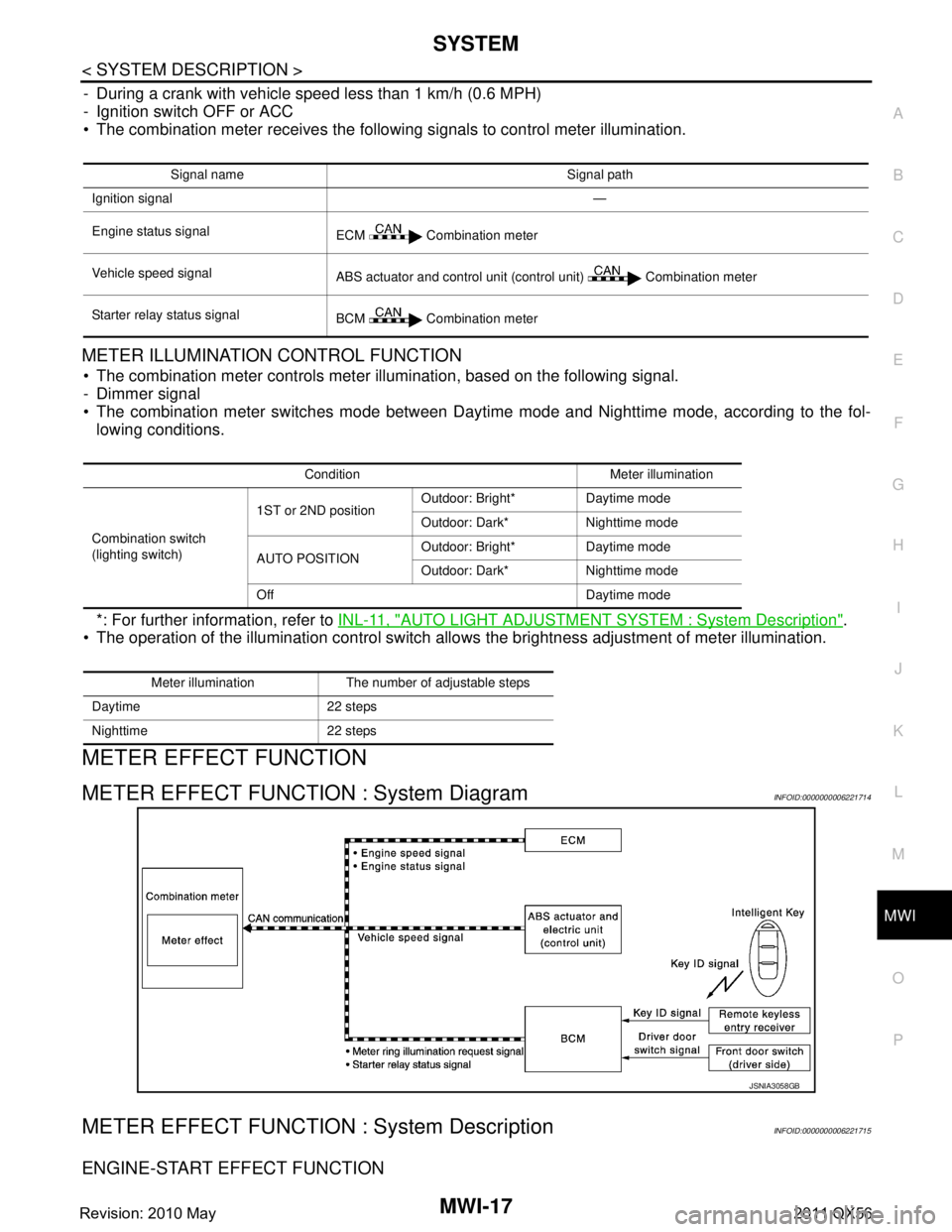
METER EFFECT FUNCTION : System DiagramINFOID:0000000006221714
METER EFFECT FUNCTION : System DescriptionINFOID:0000000006221715
ENGINE-START EFFECT FUNCTION
Signal name Signal path
Ignition signal —
Engine status signal ECM Combination meter
Vehicle speed signal ABS actuator and control unit (control unit) Combination meter
Starter relay status signal BCM Combination meter
Condition Meter illumination
Combination switch
(lighting switch) 1ST or 2ND position
Outdoor: Bright* Daytime mode
Outdoor: Dark* Nighttime mode
AUTO POSITION Outdoor: Bright* Daytime mode
Outdoor: Dark* Nighttime mode
Off Daytime mode
Meter illumination The number of adjustable steps
Daytime 22 steps
Nighttime 22 steps
JSNIA3058GB
Revision: 2010 May2011 QX56
Page 3761 of 5598

MWI-18
< SYSTEM DESCRIPTION >
SYSTEM
When recognizing an engine start, the combination meter controls the following items for producing the effect.
Speedometer
Tachometer
Engine coolant temperature gauge
Fuel gauge
Engine oil pressure gauge
Voltmeter
Meter illumination
Meter and Illumination Operations During Engine-start Effect
The combination meter controls the following items during the engine-start effect.
NOTE:
The pointers are stopped and illumination is turned off while cranking the engine.
Engine Start Judgement
The combination meter judges “engine-start” and activates the engine-start effect only once when the follow-
ing operational conditions are all satisfied.
NOTE:
Engine-start effect exits when any of the above operat ional conditions is cancelled during the engine-start
effect.
Signal path
The combination meter judges “engine-start,” according to the following signals and activates the engine-start
effect function.
DRIVER WELCOME FUNCTION
Control item Operation
Speedometer Sweeps the pointer.
Tachometer Sweeps the pointer.
Engine coolant temperature gauge Stops the pointer.
Fuel gauge Stops the pointer.
Engine oil pressure gauge Stops the pointer.
Voltmeter Stops the pointer.
Meter illumination Pointers Turns on the illumination at the effect level.
Information display Turns on the illumination at the normal brightness level.
Other than those above Increases the brightness to the effect level in stages.
Condition
Ignition switch ON position
Vehicle speed Less than 1 km/h (0.6 MPH)
Engine state Other than the time of cranking the engine
500 rpm or more
Information display
(SETTING) The setting of “EFFECT” is “ON.”
Signal name Signal path
Ignition signal —
Starter relay status signal BCM Combination meter
Engine speed signal ECM Combination meter
Engine status signal
Vehicle speed signal ABS actuator and electric unit (control unit) Combination meter
Revision: 2010 May2011 QX56
Page 3762 of 5598
MWI
SYSTEMMWI-19
< SYSTEM DESCRIPTION >
C
DE
F
G H
I
J
K L
M B A
O P
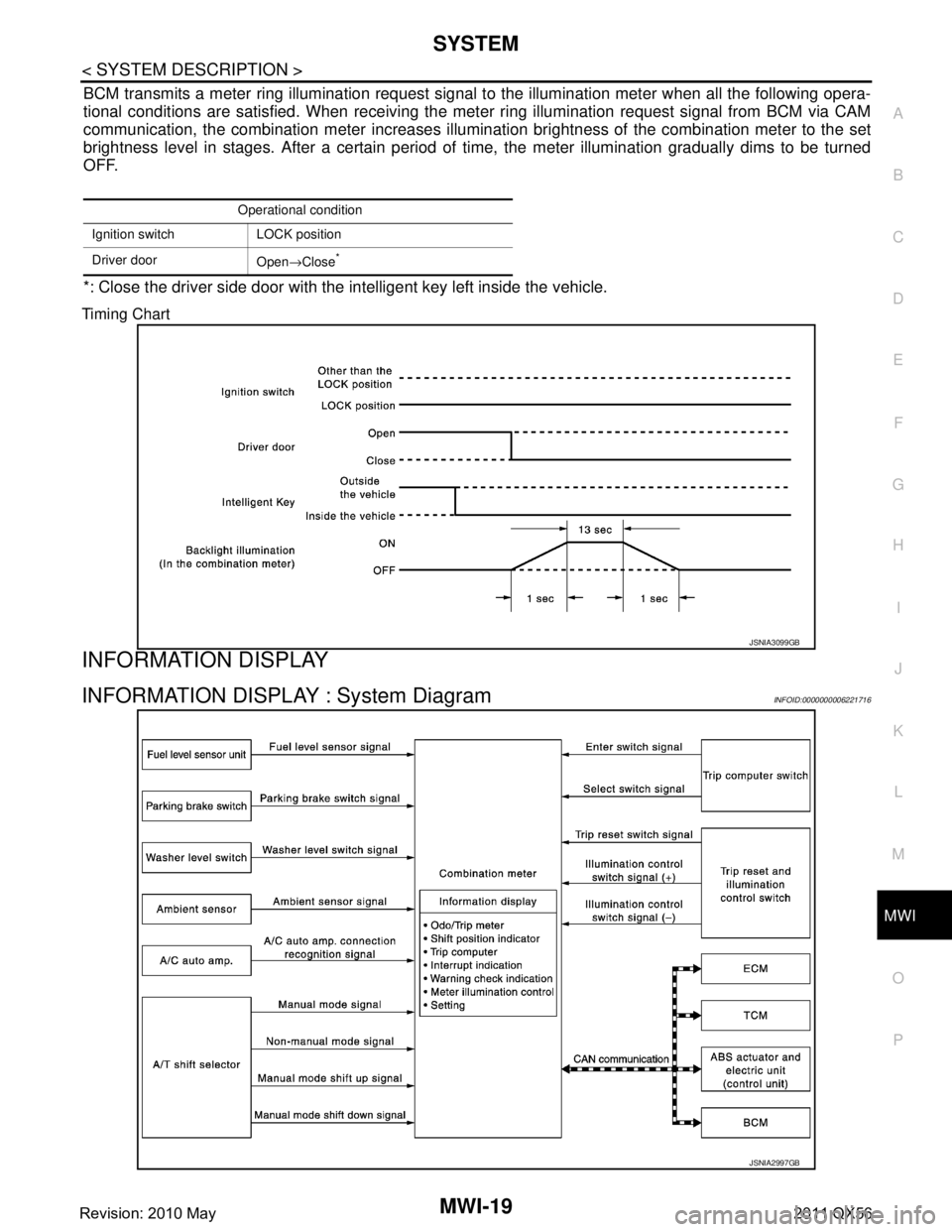
BCM transmits a meter ring illumination request signal to the illumination meter when all the following opera-
tional conditions are satisfied. When receiving the meter ring illumination request signal from BCM via CAM
communication, the combination meter increases illuminat ion brightness of the combination meter to the set
brightness level in stages. After a certain period of time, the meter illumination gradually dims to be turned
OFF.
*: Close the driver side door with the intelligent key left inside the vehicle.
Timing Chart
INFORMATION DISPLAY
INFORMATION DISPLAY : System DiagramINFOID:0000000006221716
Operational condition
Ignition switch LOCK position
Driver door Open→Close
*
JSNIA3099GB
JSNIA2997GB
Revision: 2010 May2011 QX56