2011 INFINITI QX56 engine
[x] Cancel search: enginePage 5426 of 5598

WCS-22
< ECU DIAGNOSIS INFORMATION >
COMBINATION METER
ECU DIAGNOSIS INFORMATION
COMBINATION METER
Reference ValueINFOID:0000000006222688
VALUES ON THE DIAGNOSIS TOOL
Monitor Item Condition Value/Status
SPEED METER
[km/h] Ignition switch
ON
While driving Input value of vehicle speed signal
(CAN communication signal)
NOTE:
655.35 is displayed when the malfunc-
tion signal is received
SPEED OUTPUT
[km/h] Ignition switch
ON
While driving Output value of vehicle speed signal
(CAN communication signal)
NOTE:
655.35 is displayed when the malfunc-
tion signal is received
ODO OUTPUT
[km/h or mph] Ignition switch
ON
—Output value of odometer signal (CAN
communication signal)
TACHO METER
[rpm] Ignition switch
ON
Engine running Input value of engine speed signal
(CAN communication signal)
NOTE:
8191.875 is displayed when the mal-
function signal is received
FUEL METER
[L] Ignition switch
ON
— Input value of fuel level sensor signal
W TEMP METER
[ ° C] Ignition switch
ON
—Input value of engine coolant tempera-
ture signal (CAN communication sig-
nal)
NOTE:
215 is displayed when the malfunction
signal is input
ABS W/L Ignition switch
ONABS warning lamp ON On
ABS warning lamp OFF Off
VDC/TCS IND Ignition switch
ONVDC OFF indicator lamp ON On
VDC OFF indicator lamp OFF Off
SLIP IND Ignition switch
ONVDC warning lamp ON On
VDC warning lamp OFF Off
BRAKE W/L Ignition switch
ONBrake warning lamp ON On
Brake warning lamp OFF Off
DOOR W/L Ignition switch
ONDoor open warning ON On
Other than the above Off
HI-BEAM IND Ignition switch
ONHigh-beam indicator lamp ON On
High-beam indicator lamp OFF Off
TURN IND Ignition switch
ONTurn signal indicator lamp ON On
Turn signal indicator lamp OFF Off
FR FOG IND Ignition switch
ONNOTE:
This item is displayed, but cannot be moni-
tored.
Off
RR FOG IND Ignition switch
ONNOTE:
This item is displayed, but cannot be moni-
tored.
Off
Revision: 2010 May2011 QX56
Page 5428 of 5598

WCS-24
< ECU DIAGNOSIS INFORMATION >
COMBINATION METER
DCA INDIgnition switch
ONNOTE:
This item is displayed, but cannot be moni-
tored.
Off
CHECK SUS IND Ignition switch
ONCK SUSP indicator lamp ON On
CK SUSP indicator lamp OFF Off
LCD Ignition switch
ON
During engine start in
formation indication B&P I
Ignition switch
ACC During engine start information indication B&P N
Ignition switch
LOCK During key ID warning indication ID NG
Ignition switch
LOCK During steering lock information indication ROTAT
Ignition switch
LOCK During P position warning indication SFT P
Ignition switch
LOCK During Intelligent Key insert information in-
dication
INSRT
Ignition switch
LOCK During Intelligent Key low battery warning
indication
BATT
Ignition switch
ON During take away warning indication NO KY
Ignition switch
LOCK During key warnin
g indication OUTKY
Ignition switch
ON During ACC warning indication LK WN
ACC TARGET Ignition switch
ONDuring vehicle ahead detection indicator in-
dication
On
Other than the above Off
ACC DISTANCE Ignition switch
ONWhen following distance set to “LONG” LONG
When following distance set to “MIDDLE” MID
When following distance set to “SHORT” SHORT
Set distance indicator not displayed Off
ACC OWN VHL Ignition switch
ONDuring own vehicle indicator indication On
Other than the above Off
ACC SET SPEED Ignition switch
ONDuring set vehicle speed indicator not dis-
played
Off
During set vehicle speed indicator dis-
played Indicates the set vehicle speed
ACC UNIT Ignition switch
ONSet vehicle speed indicator unit display ON On
Set vehicle speed indicator unit display OFF Off
Monitor Item Condition Value/Status
Revision: 2010 May2011 QX56
Page 5433 of 5598

WCS
COMBINATION METERWCS-29
< ECU DIAGNOSIS INFORMATION >
C
DE
F
G H
I
J
K L
M B A
O P
Fail-SafeINFOID:0000000006222689
FA I L - S A F E
The combination meter activates the fail-safe contro l if CAN communication with each unit is malfunctioning.
37
(R/Y) Ground Non-manual mode signal Input Ignition
switch
ONSelector manual mode po-
sition
12 V
Other than the above 0 V
38
(L/W) Ground Manual mode shift down
signal InputIgnition
switch
ON Selector lever DOWN oper-
ation
0 V
Other than the above 12 V
39
(Y/B) Ground Manual mode shift up sig-
nal InputIgnition
switch
ON Selector lever UP operation 0 V
Other than the above 12 V
40
(G/W) Ground Manual mode signal Input Ignition
switch
ONSelector manual mode po-
sition
0 V
Other than the above 12 V
Te r m i n a l N o .
(Wire color) Description
ConditionVa l u e
(Approx.)
+ – Signal name Input/
Output
Function Specifications
Speedometer
Reset to zero by suspending communication.
Tachometer
Engine coolant temperature gauge
Engine oil pressure gauge
Illumination control When suspending communication, changes to nighttime mode.
Information display Odo/trip meter An indicated value is maintained at communications blackout.
Shift position indicator The display turns OFF by suspending communication.
Door open warning The display turns OFF by suspending communication.
Buzzer The buzzer turns OFF by suspending communication.
Revision: 2010 May2011 QX56
Page 5434 of 5598

WCS-30
< ECU DIAGNOSIS INFORMATION >
COMBINATION METER
DTC Index
INFOID:0000000006222690
Warning lamp/indicator lamp ABS warning lamp
The lamp turns ON by suspending communication.
VDC warning lamp
Brake warning lamp
IBA OFF indicator lamp
4WD warning lamp
Malfunction indicator lamp
VDC OFF indicator lamp
CRUISE warning lamp
Low tire pressure warning lamp The lamp blinking caused by suspending communication.
High beam indicator lamp
The lamp turns OFF by suspending communication.
Turn signal indicator lamp
Tail lamp indicator lamp
A/T CHECK indicator lamp
Key warning lamp
ATP warning lamp
Lane departure warning lamp
LDP ON indicator lamp
CRUISE indicator lamp
Oil pressure warning lamp
SNOW mode indicator lamp
TOW mode indicator lamp
CK SUSP indicator lamp
BSW indicator lamp
Function Specifications
Display contents of CONSULT-III Diagnostic item is detected when... Refer to
CAN COMM CIRCUIT
[U1000] When combination meter is not transmitting or receiving CAN communication signal
for 2 seconds or more. MWI-59,
"Diagnosis
Procedure"
CONTROL UNIT (CAN)
[U1010]
When detecting error during the initial diagnosis of the CAN controller of combina-
tion meter. MWI-60, "Diagnosis
Procedure"
VEHICLE SPEED
[B2205]
The abnormal vehicle sp
eed signal is input from the ABS actuator and electric unit
(control unit) for 2 seconds or more. MWI-61, "Diagnosis
Procedure"
ENGINE SPEED
[B2267]
If ECM continuously transmits abnormal engine speed signals for 2 seconds or
more. MWI-62, "Diagnosis
Procedure"
WATER TEMP
[B2268]
If ECM continuously transmits abnormal engine coolant temperature signals for 60
seconds or more. MWI-63, "Diagnosis
Procedure"
Revision: 2010 May2011 QX56
Page 5450 of 5598

WCS-46
< SYMPTOM DIAGNOSIS >
THE PARKING BRAKE RELEASE WARNING CONTINUES SOUNDING, OR
DOES NOT SOUND
THE PARKING BRAKE RELEASE WARNING CONTINUES SOUNDING, OR
DOES NOT SOUND
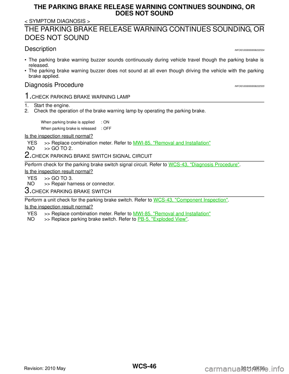
DescriptionINFOID:0000000006222534
The parking brake warning buzzer sounds continuously during vehicle travel though the parking brake is
released.
The parking brake warning buzzer does not sound at a ll even though driving the vehicle with the parking
brake applied.
Diagnosis ProcedureINFOID:0000000006222535
1.CHECK PARKING BRAKE WARNING LAMP
1. Start the engine.
2. Check the operation of the brake warni ng lamp by operating the parking brake.
Is the inspection result normal?
YES >> Replace combination meter. Refer to MWI-85, "Removal and Installation"
NO >> GO TO 2.
2.CHECK PARKING BRAKE SWITCH SIGNAL CIRCUIT
Perform check for the parking brake switch signal circuit. Refer to WCS-43, "
Diagnosis Procedure".
Is the inspection result normal?
YES >> GO TO 3.
NO >> Repair harness or connector.
3.CHECK PARKING BRAKE SWITCH
Perform a unit check for the parking brake switch. Refer to WCS-43, "
Component Inspection".
Is the inspection result normal?
YES >> Replace combination meter. Refer to MWI-85, "Removal and Installation"
NO >> Replace parking brake switch. Refer to PB-5, "Exploded View".
When parking brake is applied : ON
When parking brake is released : OFF
Revision: 2010 May2011 QX56
Page 5453 of 5598

PRECAUTIONSWT-3
< PRECAUTION >
C
DF
G H
I
J
K L
M A
B
WT
N
O P
PRECAUTION
PRECAUTIONS
Precaution for Supplemental Restraint System (SRS) "AIR BAG" and "SEAT BELT
PRE-TENSIONER"
INFOID:0000000006256474
The Supplemental Restraint System such as “A IR BAG” and “SEAT BELT PRE-TENSIONER”, used along
with a front seat belt, helps to reduce the risk or severi ty of injury to the driver and front passenger for certain
types of collision. This system includes seat belt switch inputs and dual stage front air bag modules. The SRS
system uses the seat belt switches to determine the front air bag deployment, and may only deploy one front
air bag, depending on the severity of a collision and whether the front occupants are belted or unbelted.
Information necessary to service the system safely is included in the “SRS AIR BAG” and “SEAT BELT” of this
Service Manual.
WARNING:
• To avoid rendering the SRS inoper ative, which could increase the risk of personal injury or death in
the event of a collision that would result in air ba g inflation, all maintenance must be performed by
an authorized NISSAN/INFINITI dealer.
Improper maintenance, including in correct removal and installation of the SRS, can lead to personal
injury caused by unintentional act ivation of the system. For removal of Spiral Cable and Air Bag
Module, see the “SRS AIR BAG”.
Do not use electrical test equipm ent on any circuit related to the SRS unless instructed to in this
Service Manual. SRS wiring harnesses can be identi fied by yellow and/or orange harnesses or har-
ness connectors.
PRECAUTIONS WHEN USING POWER TOOLS (AIR OR ELECTRIC) AND HAMMERS
WARNING:
When working near the Air Bag Diagnosis Sensor Unit or other Air Bag System sensors with the
ignition ON or engine running, DO NOT use air or electric power tools or strike near the sensor(s)
with a hammer. Heavy vibration could activate the sensor(s) and deploy the air bag(s), possibly
causing serious injury.
When using air or electric power tools or hammers , always switch the ignition OFF, disconnect the
battery, and wait at least 3 minutes before performing any service.
Precaution Necessary for Steering Wh eel Rotation after Battery Disconnect
INFOID:0000000006256475
NOTE:
Before removing and installing any control units, first tu rn the push-button ignition switch to the LOCK posi-
tion, then disconnect both battery cables.
After finishing work, confirm that all control unit connectors are connected properly, then re-connect both
battery cables.
Always use CONSULT-III to perform self-diagnosis as a part of each function inspection after finishing work.
If a DTC is detected, perform trouble diagnos is according to self-diagnosis results.
For vehicle with steering lock unit, if the battery is disconnected or discharged, the steering wheel will lock and
cannot be turned.
If turning the steering wheel is required with the batte ry disconnected or discharged, follow the operation pro-
cedure below before starting the repair operation.
OPERATION PROCEDURE
1. Connect both battery cables. NOTE:
Supply power using jumper cables if battery is discharged.
2. Turn the push-button ignition switch to ACC position. (At this time, the steering lock will be released.)
3. Disconnect both battery cables. The steering lock wil l remain released with both battery cables discon-
nected and the steering wheel can be turned.
4. Perform the necessary repair operation.
Revision: 2010 May2011 QX56
Page 5460 of 5598

WT-10
< SYSTEM DESCRIPTION >
SYSTEM
*: Mainly used for the tire inflation indicator function.
LOW TIRE PRESSURE WARNING LAMP CONTROL CONDITION
Uses CAN communication from the low tire pressure warning control unit to illuminate the low tire pressure
warning lamp on the combination meter.
*: Tire pressure at each condition differs.
HAZARD WARNING LAMP CONTROL CONDITION
The low tire pressure warning control unit transmits a hazard request signal to BCM. BCM blinks the hazard
warning lamp, according to the signal.
The hazard warning lamp blinks under the following conditions.
Condition of Blinking The Hazard Warning Lamp When wake-up of registered wheel has been completed. Refer to WT-28, "Work Procedure".
When ID registration is completed. Refer to WT-29, "
Work Procedure".
During the use of the tire inflation indicator function.
HORN CONTROL CONDITION
The low tire pressure warning control unit transmits a horn request signal to BCM. BCM controls horn sound,
according to the signal.
The horn sounds under the following condition.
Condition of Sounding Horn During the use of tire inflation indicator function.
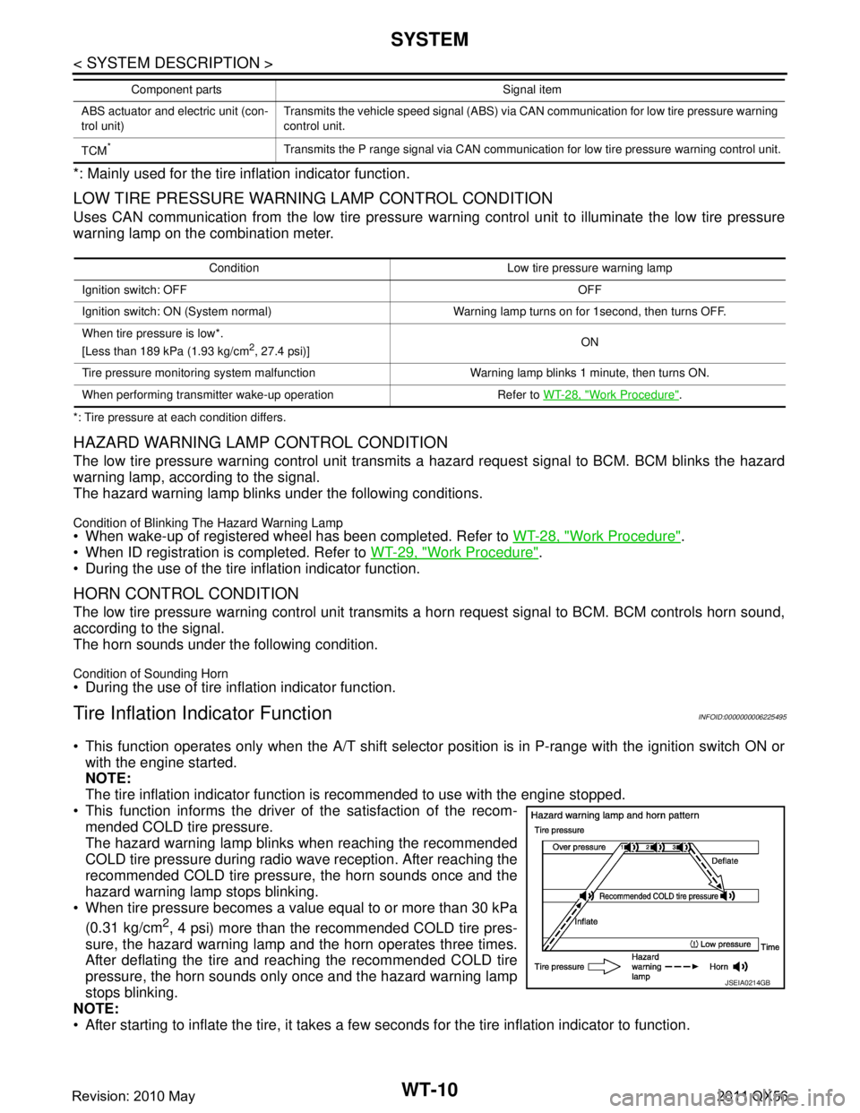
Tire Inflation Indicator FunctionINFOID:0000000006225495
This function operates only when the A/T shift selector position is in P-range with the ignition switch ON or
with the engine started.
NOTE:
The tire inflation indicator function is recommended to use with the engine stopped.
This function informs the driver of the satisfaction of the recom- mended COLD tire pressure.
The hazard warning lamp blinks when reaching the recommended
COLD tire pressure during radio wave reception. After reaching the
recommended COLD tire pressure, the horn sounds once and the
hazard warning lamp stops blinking.
When tire pressure becomes a value equal to or more than 30 kPa
(0.31 kg/cm
2, 4 psi) more than the recommended COLD tire pres-
sure, the hazard warning lamp and the horn operates three times.
After deflating the tire and reaching the recommended COLD tire
pressure, the horn sounds only once and the hazard warning lamp
stops blinking.
NOTE:
After starting to inflate the tire, it takes a few seconds for the tire inflation indicator to function.
ABS actuator and electric unit (con-
trol unit) Transmits the vehicle speed signal (ABS) via CAN communication for low tire pressure warning
control unit.
TCM
*Transmits the P range signal via CAN communication for low tire pressure warning control unit.
Component parts Signal item
Condition Low tire pr
essure warning lamp
Ignition switch: OFF OFF
Ignition switch: ON (System normal) Warning lamp turns on for 1second, then turns OFF.
When tire pressure is low*.
[Less than 189 kPa (1.93 kg/cm
2, 27.4 psi)] ON
Tire pressure monitoring system malfunction Warning lamp blinks 1 minute, then turns ON.
When performing transmitter wake-up operation Refer to WT-28, "
Work Procedure".
JSEIA0214GB
Revision: 2010 May2011 QX56
Page 5464 of 5598

WT-14
< ECU DIAGNOSIS INFORMATION >
LOW TIRE PRESSURE WARNING CONTROL UNIT
ECU DIAGNOSIS INFORMATION
LOW TIRE PRESSURE WARNING CONTROL UNIT
Reference ValueINFOID:0000000006225497
VALUES ON THE DIAGNOSIS TOOL
CAUTION:
The reference values in the table below come from the control unit calculation data. The normal values
may in some cases be displayed even though the power circuit (harness) is open or shorted.
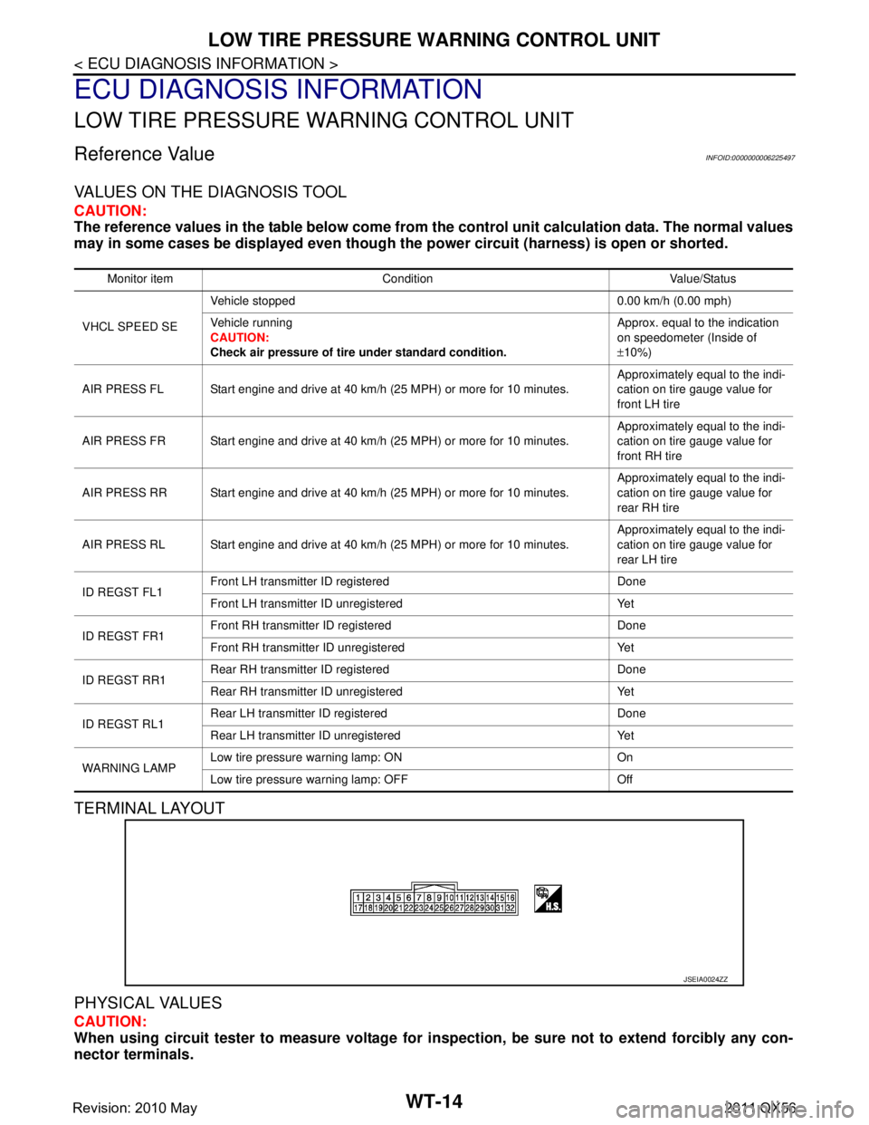
TERMINAL LAYOUT
PHYSICAL VALUES
CAUTION:
When using circuit tester to measure voltage for in spection, be sure not to extend forcibly any con-
nector terminals.
Monitor item Condition Value/Status
VHCL SPEED SE Vehicle stopped 0.00 km/h (0.00 mph)
Vehicle running
CAUTION:
Check air pressure of tire under standard condition. Approx. equal to the indication
on speedometer (Inside of
±
10%)
AIR PRESS FL Start engine and drive at 40 km/h (25 MPH) or more for 10 minutes. Approximately equal to the indi-
cation on tire gauge value for
front LH tire
AIR PRESS FR Start engine and drive at 40 km/h (25 MPH) or more for 10 minutes. Approximately equal to the indi-
cation on tire gauge value for
front RH tire
AIR PRESS RR Start engine and drive at 40 km/h (25 MPH) or more for 10 minutes. Approximately equal to the indi-
cation on tire gauge value for
rear RH tire
AIR PRESS RL Start engine and drive at 40 km/h (25 MPH) or more for 10 minutes. Approximately equal to the indi-
cation on tire gauge value for
rear LH tire
ID REGST FL1 Front LH transmitter ID registered Done
Front LH transmitter ID unregistered Yet
ID REGST FR1 Front RH transmitter ID registered Done
Front RH transmitter ID unregistered Yet
ID REGST RR1 Rear RH transmitter ID registered Done
Rear RH transmitter ID unregistered Yet
ID REGST RL1 Rear LH transmitter ID registered Done
Rear LH transmitter ID unregistered Yet
WARNING LAMP Low tire pressure
warning lamp: ON On
Low tire pressure warning lamp: OFF Off
JSEIA0024ZZ
Revision: 2010 May2011 QX56