2011 INFINITI QX56 height
[x] Cancel search: heightPage 4264 of 5598
REAR LOWER LINK & COIL SPRINGRSU-9
< REMOVAL AND INSTALLATION >
C
DF
G H
I
J
K L
M A
B
RSU
N
O P
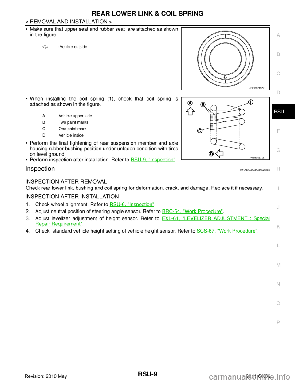
Make sure that upper seat and rubber seat are attached as shown in the figure.
When installing the coil spring (1), check that coil spring is attached as shown in the figure.
Perform the final tightening of rear suspension member and axle housing rubber bushing position under unladen condition with tires
on level ground.
Perform inspection after installation. Refer to RSU-9, "
Inspection".
InspectionINFOID:0000000006225665
INSPECTION AFTER REMOVAL
Check rear lower link, bushing and coil spring for defor mation, crack, and damage. Replace it if necessary.
INSPECTION AFTER INSTALLATION
1. Check wheel alignment. Refer to RSU-6, "Inspection".
2. Adjust neutral position of steering angle sensor. Refer to BRC-64, "
Work Procedure".
3. Adjust levelizer adjustment of height sensor. Refer to EXL-61, "
LEVELIZER ADJUSTMENT : Special
Repair Requirement".
4. Check standard vehicle height setting of vehicle height sensor. Refer to SCS-67, "
Work Procedure".
: Vehicle outside
JPEIB0219ZZ
A : Vehicle upper side
B : Two paint marks
C : One paint mark
D : Vehicle inside
JPEIB0237ZZ
Revision: 2010 May2011 QX56
Page 4266 of 5598
REAR SHOCK ABSORBERRSU-11
< REMOVAL AND INSTALLATION >
C
DF
G H
I
J
K L
M A
B
RSU
N
O P
Inadvertent piping removal causes fluid to splatter.
2. Remove tires with power tool. Refer to WT-64, "
Removal and Installation".
3. Remove height sensor from rear lower link (right side). Refer to EXL-136, "
Removal and Installation".
4. Remove vehicle height sensor from rear lower link (left side). Refer to SCS-98, "
Removal and Installa-
tion".
5. Remove air tube from shock absorber assembly. Refer to SCS-95, "
Removal and Installation".
6. Remove middle tube assembly from shock absorber assembly. (With HBMC) Refer to SCS-44, "
REAR
TUBE ASSEMBLY : Removal and Installation".
7. Remove shock absorber mounting bolt (lower side).
8. Remove piston rod lock nut.
9. Remove bracket, bushings, and shock absorber. (With HBMC)
10. Remove washers, bushings, and shock absorber. (Without HBMC)
11. Perform inspection after removal. Refer to RSU-11, "
Inspection and Adjustment".
INSTALLATION
Note the following, and install in the reverse order of removal.
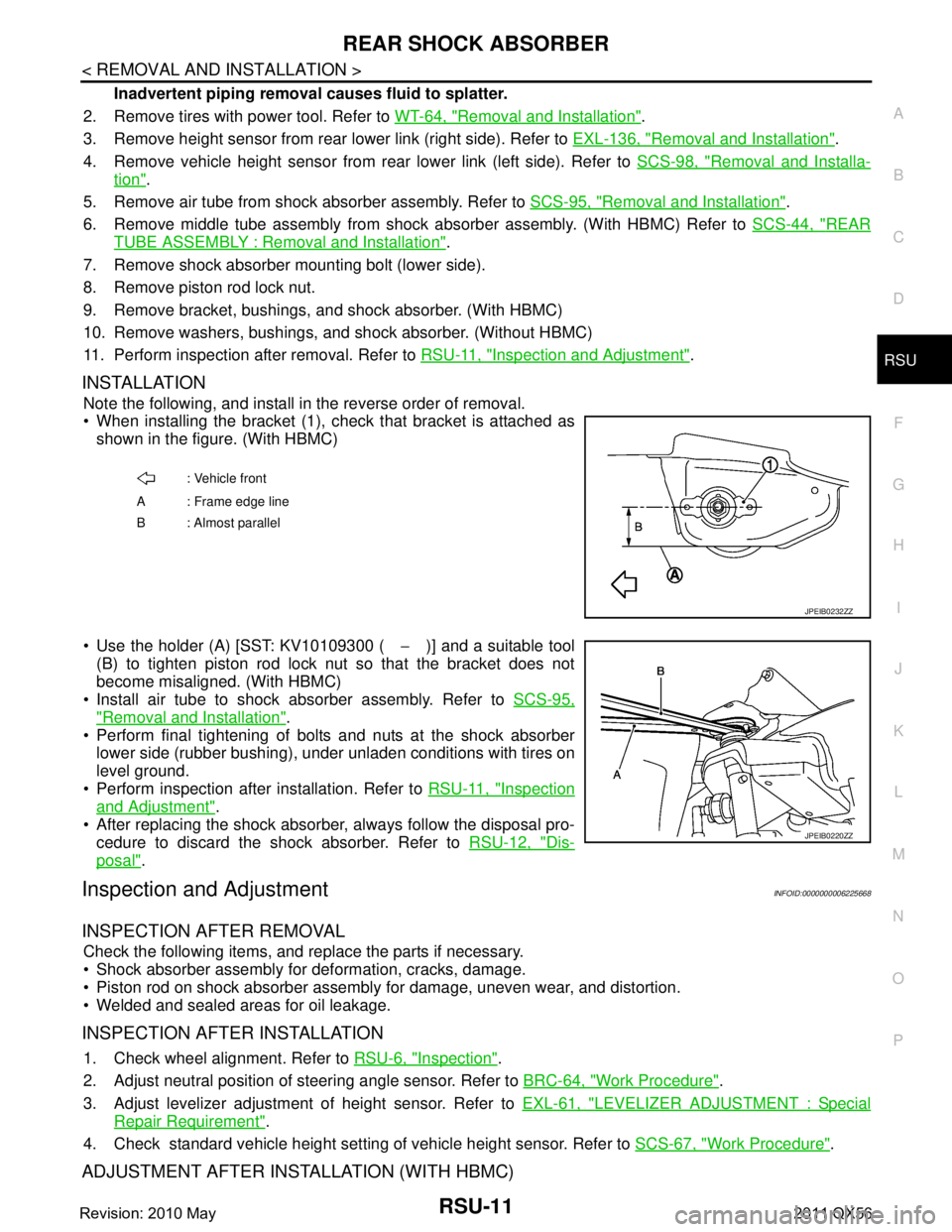
When installing the bracket (1), check that bracket is attached as
shown in the figure. (With HBMC)
Use the holder (A) [SST: KV10109300 ( −)] and a suitable tool
(B) to tighten piston rod lock nut so that the bracket does not
become misaligned. (With HBMC)
Install air tube to shock absorber assembly. Refer to SCS-95,
"Removal and Installation".
Perform final tightening of bolts and nuts at the shock absorber
lower side (rubber bushing), under unladen conditions with tires on
level ground.
Perform inspection after installation. Refer to RSU-11, "
Inspection
and Adjustment".
After replacing the shock absorber, always follow the disposal pro- cedure to discard the shock absorber. Refer to RSU-12, "
Dis-
posal".
Inspection and AdjustmentINFOID:0000000006225668
INSPECTION AFTER REMOVAL
Check the following items, and replace the parts if necessary.
Shock absorber assembly for deformation, cracks, damage.
Piston rod on shock absorber assembly for damage, uneven wear, and distortion.
Welded and sealed areas for oil leakage.
INSPECTION AFTER INSTALLATION
1. Check wheel alignment. Refer to RSU-6, "Inspection".
2. Adjust neutral position of steering angle sensor. Refer to BRC-64, "
Work Procedure".
3. Adjust levelizer adjustment of height sensor. Refer to EXL-61, "
LEVELIZER ADJUSTMENT : Special
Repair Requirement".
4. Check standard vehicle height setting of vehicle height sensor. Refer to SCS-67, "
Work Procedure".
ADJUSTMENT AFTER INSTALLATION (WITH HBMC)
: Vehicle front
A : Frame edge line
B: Almost parallel
JPEIB0232ZZ
JPEIB0220ZZ
Revision: 2010 May2011 QX56
Page 4269 of 5598
RSU-14
< REMOVAL AND INSTALLATION >
SUSPENSION ARM
1. Move the ball joint at least ten times by hand to check for smooth movement.
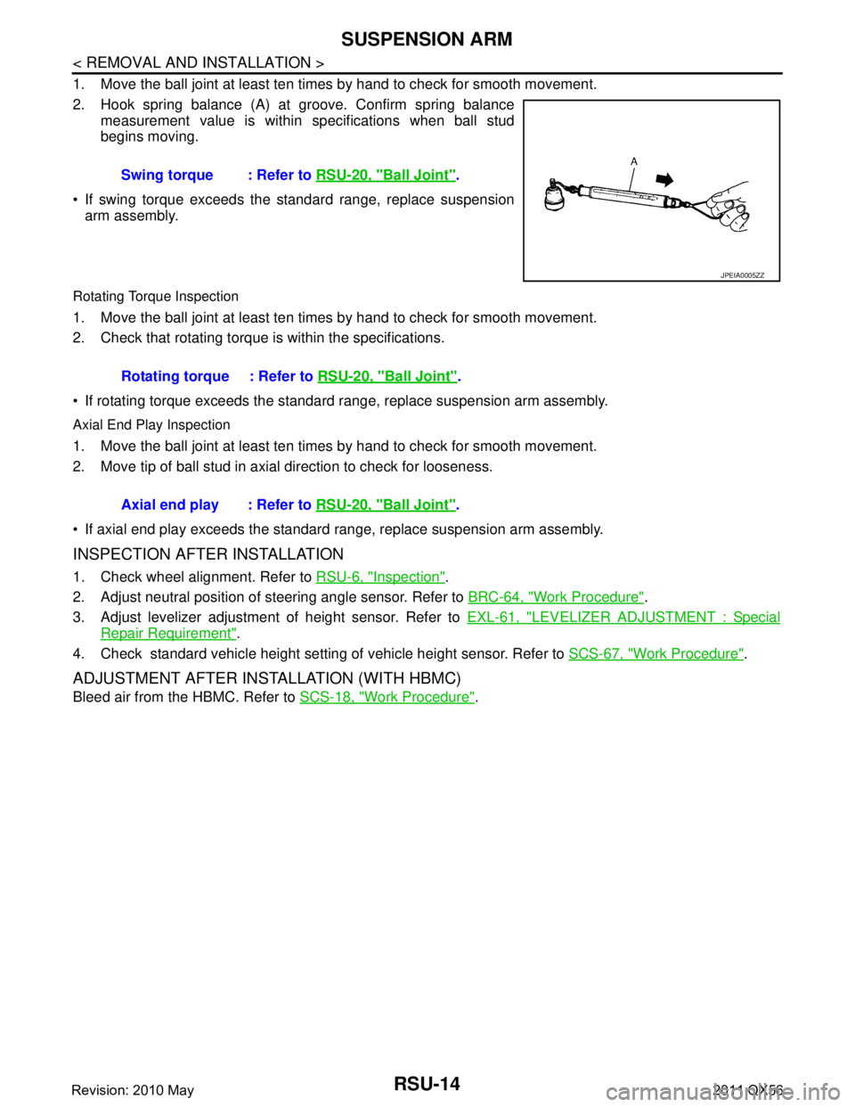
2. Hook spring balance (A) at groove. Confirm spring balancemeasurement value is within specifications when ball stud
begins moving.
If swing torque exceeds the standard range, replace suspension arm assembly.
Rotating Torque Inspection
1. Move the ball joint at least ten times by hand to check for smooth movement.
2. Check that rotating torque is within the specifications.
If rotating torque exceeds the standard range, replace suspension arm assembly.
Axial End Play Inspection
1. Move the ball joint at least ten times by hand to check for smooth movement.
2. Move tip of ball stud in axial direction to check for looseness.
If axial end play exceeds the standard r ange, replace suspension arm assembly.
INSPECTION AFTER INSTALLATION
1. Check wheel alignment. Refer to RSU-6, "Inspection".
2. Adjust neutral position of steering angle sensor. Refer to BRC-64, "
Work Procedure".
3. Adjust levelizer adjustment of height sensor. Refer to EXL-61, "
LEVELIZER ADJUSTMENT : Special
Repair Requirement".
4. Check standard vehicle height setting of vehicle height sensor. Refer to SCS-67, "
Work Procedure".
ADJUSTMENT AFTER INSTALLATION (WITH HBMC)
Bleed air from the HBMC. Refer to SCS-18, "Work Procedure".
Swing torque : Refer to
RSU-20, "
Ball Joint".
JPEIA0005ZZ
Rotating torque : Refer to RSU-20, "Ball Joint".
Axial end play : Refer to RSU-20, "
Ball Joint".
Revision: 2010 May2011 QX56
Page 4273 of 5598
RSU-18
< UNIT REMOVAL AND INSTALLATION >
REAR SUSPENSION MEMBER
UNIT REMOVAL AND INSTALLATION
REAR SUSPENSION MEMBER
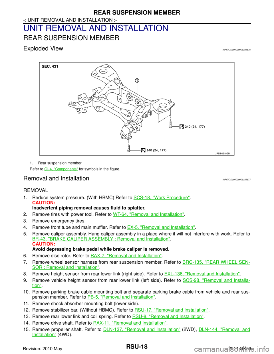
Exploded ViewINFOID:0000000006225676
Removal and InstallationINFOID:0000000006225677
REMOVAL
1. Reduce system pressure. (With HBMC) Refer to SCS-18, "Work Procedure".
CAUTION:
Inadvertent piping removal causes fluid to splatter.
2. Remove tires with power tool. Refer to WT-64, "
Removal and Installation".
3. Remove emergency tires.
4. Remove front tube and main muffler. Refer to EX-5, "
Removal and Installation".
5. Remove caliper assembly. Hang caliper assembly in a place where it will not interfere with work. Refer to BR-43, "
BRAKE CALIPER ASSEMBLY : Removal and Installation".
CAUTION:
Avoid depressing brake pedal wh ile brake caliper is removed.
6. Remove disc rotor. Refer to RAX-7, "
Removal and Installation".
7. Remove wheel sensor harness from rear suspension member. Refer to BRC-135, "
REAR WHEEL SEN-
SOR : Removal and Installation".
8. Remove height sensor from rear lower link (right side). Refer to EXL-136, "
Removal and Installation".
9. Remove vehicle height sensor from rear lower link (left side). Refer to SCS-98, "
Removal and Installa-
tion".
10. Remove parking brake cable mounting bolt and separa te parking brake cable from vehicle and rear sus-
pension member. Refer to PB-5, "
Removal and Installation".
11. Remove shock absorber mounting bolt (lower side).
12. Remove stabilizer bar. (Without HBMC). Refer to RSU-17, "
Removal and Installation".
13. Remove rear lower link and coil spring. Refer to RSU-8, "
Removal and Installation".
14. Remove drive shaft. Refer to RAX-11, "
Removal and Installation".
15. Remove propeller shaft. Refer to DLN-137, "
Removal and Installation" (2WD), DLN-144, "Removal and
Installation" (4WD).
1. Rear suspension member
Refer to GI-4, "
Components" for symbols in the figure.
JPEIB0218GB
Revision: 2010 May2011 QX56
Page 4274 of 5598
REAR SUSPENSION MEMBERRSU-19
< UNIT REMOVAL AND INSTALLATION >
C
DF
G H
I
J
K L
M A
B
RSU
N
O P
16. Remove final drive. Refer to DLN-201, "Removal and Installation".
17. Remove rear tube assembly A and rear tube assembly B. (With HBMC) Refer to SCS-44, "
REAR TUBE
ASSEMBLY : Removal and Installation".
18. Set suitable jack under rear suspension member.
19. Slowly lower jack, then remove rear suspension member, suspension arm, front lower link, wheel hub and housing from vehicle as a unit.
20. Remove mounting bolts and nuts, then remove suspension arm, front lower link, wheel hub and housing from rear suspension member.
21. Perform inspection after removal. Refer to RSU-19, "
Inspection and Adjustment".
INSTALLATION
Note the following, and install in the reverse order of the removal.
Perform the final tightening of each of parts under unladen conditions, which were removed when removing
rear suspension assembly.
Perform inspection after installation. Refer to RSU-19, "
Inspection and Adjustment".
Perform adjustment after installation. (With HBMC) Refer to RSU-19, "
Inspection and Adjustment".
Inspection and AdjustmentINFOID:0000000006225678
INSPECTION AFTER REMOVAL
Check rear suspension member for deformation, cracks, or any other damage. Replace if necessary.
INSPECTION AFTER INSTALLATION
1. Adjust parking brake operation (stroke). Refer to PB-3, "Inspection and Adjustment".
2. Check wheel alignment. Refer to RSU-6, "
Inspection".
3. Adjust neutral position of steering angle sensor. Refer to BRC-64, "
Work Procedure".
4. Adjust levelizer adjustment of height sensor. Refer to EXL-61, "
LEVELIZER ADJUSTMENT : Special
Repair Requirement".
5. Check standard vehicle height setting of vehicle height sensor. Refer to SCS-67, "
Work Procedure".
6. Check wheel sensor harness for proper connection. Refer to BRC-135, "
REAR WHEEL SENSOR :
Exploded View"
ADJUSTMENT AFTER INSTALLATION (WITH HBMC)
Bleed air from the HBMC. Refer to SCS-18, "Work Procedure".
Revision: 2010 May2011 QX56
Page 4275 of 5598
RSU-20
< SERVICE DATA AND SPECIFICATIONS (SDS)
SERVICE DATA AND SPECIFICATIONS (SDS)
SERVICE DATA AND SPECIFICATIONS (SDS)
SERVICE DATA AND SPECIFICATIONS (SDS)
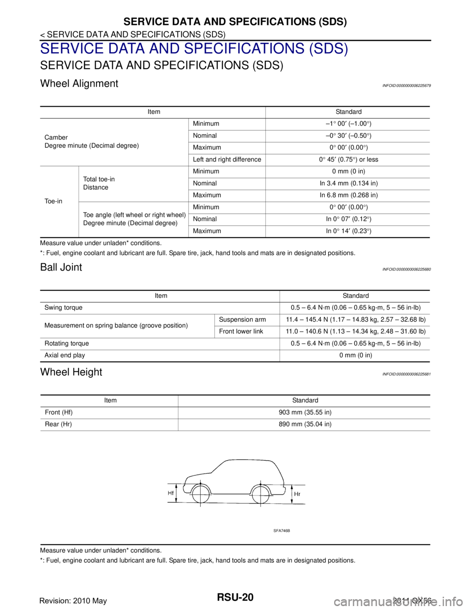
Wheel AlignmentINFOID:0000000006225679
Measure value under unladen* conditions.
*: Fuel, engine coolant and lubricant are full. Spare tire, jack, hand tools and mats are in designated positions.
Ball JointINFOID:0000000006225680
Wheel HeightINFOID:0000000006225681
Measure value under unladen* conditions.
*: Fuel, engine coolant and lubricant are full. Spare tire, jack, hand tools and mats are in designated positions.Item Standard
Camber
Degree minute (Decimal degree) Minimum –1
° 00 ′ (–1.00 °)
Nominal –0 ° 30 ′ (–0.50 °)
Maximum 0 ° 00 ′ (0.00 °)
Left and right difference 0 ° 45 ′ (0.75 °) or less
To e - i n Total toe-in
Distance
Minimum 0 mm (0 in)
Nominal In 3.4 mm (0.134 in)
Maximum In 6.8 mm (0.268 in)
Toe angle (left wheel or right wheel)
Degree minute (Decimal degree) Minimum 0
° 00 ′ (0.00 °)
Nominal In 0 ° 07 ′ (0.12 °)
Maximum In 0 ° 14 ′ (0.23 °)
Item Standard
Swing torque 0.5 – 6.4 N·m (0.06 – 0.65 kg-m, 5 – 56 in-lb)
Measurement on spring balance (groove position) Suspension arm 11.4 – 145.4 N (1.17 – 14.83 kg, 2.57 – 32.68 lb)
Front lower link 11.0 – 140.6 N (1.13 – 14.34 kg, 2.48 – 31.60 lb)
Rotating torque 0.5 – 6.4 N·m (0.06 – 0.65 kg-m, 5 – 56 in-lb)
Axial end play 0 mm (0 in)
Item Standard
Front (Hf) 903 mm (35.55 in)
Rear (Hr) 890 mm (35.04 in)
SFA746B
Revision: 2010 May2011 QX56
Page 4279 of 5598
SB-4
< REMOVAL AND INSTALLATION >
FRONT SEAT BELT
REMOVAL AND INSTALLATION
FRONT SEAT BELT
SEAT BELT RETRACTOR
SEAT BELT RETRACTOR : InspectionINFOID:0000000006217615
AFTER A COLLISION
WARNING:
Inspect all seat belt assemblies including retractors and attached hardware after any collision.
NISSAN/INFINITI recommends that all seat belt assemblies in use during a collision be replaced
unless the collision was minor and th e belts show no damage and continue to operate properly. Fail-
ure to do so could result in seri ous personal injury in an accident. Seat belt assemblies not in use dur-
ing a collision should also be re placed if either damage or improper operation was noted. Seat belt
pre-tensioners should be replaced even if the seat be lts were not in use during a frontal collision in
which the air bags were deployed.
Replace any seat belt assembly (including anchor bolts) if:
The seat belt is in use at the time of a collision (e xcept for minor collisions and the belts, retractors and buck-
les show no damage and continue to operate properly).
The seat belt is damaged in an accident (i.e. to rn webbing, bent retractor or guide, etc.).
The seat belt attaching point is damaged in an accident . Inspect the seat belt attaching area for damage or
distortion and repair if necessary before installing a new seat belt assembly.
Anchor bolts are deformed or worn out.
The seat belt pre-tensioners must be replaced even if t he seat belts were not in use during the collision in
which the air bags were deployed.
PRELIMINARY CHECKS
1. Check the seat belt warning lamp for proper operation as per the following:
a. Turn ignition switch ON. The seat belt warning lamp should illuminate.
b. Fasten driver seat belt. The seat belt warning lamp should turn OFF.
2. If the air bag warning lamp is blinking, perform self-diagnosis with CONSULT-III and air bag warning lamp. Refer to SRC-14, "
Description".
3. Check that the seat belt retractor, s eat belt anchor and buckle bolts are tightened firmly.
4. Check the shoulder seat belt guide and shoulder belt height adjuster for front seats. Check that guide
swivels freely and that webbing lays flat and does not bind in guide. Check that height adjuster operates
properly and holds securely.
5. Check retractor operation:
a. Fully extend the seat belt webbing and c heck for twists, tears or other damage.
b. Allow the seat belt to retract. Check that webbing retu rns smoothly and completely into the retractor. If the
seat belt does not return smoothly, wipe the inside of the loops with a clean paper cloth. Dirt build-up in the
loops of the upper anchors can cause the seat belts to retract slowly.
c. Fasten the seat belt. Check that seat belt returns sm oothly and completely to the retractor. If the webbing
does not return smoothly, the cause may be an accumulation of dust or dirt. Use the “SEAT BELT TAPE
SET” and perform the following steps.
Inspect the front seat belt through-anchor
1. Pull the seat belt out to a length of 500 mm (19.69 in) or more.
2. Fix the seat belt at the center pillar webbing opening with a clip or other device.
3. Pass a thin wire through the through-anchor webbing opening. Hold both ends of the wire and pull it tightly while moving it up and down several times along the webbing opening surface to remove dirt
stuck there.
4. Any dirt that cannot be removed with the wir e can be removed by cleaning the opening with a clean
cloth.
5. Apply tape at the point where the webbi ng contacts the through-anchor webbing opening.
NOTE:
Apply the tape so that there is no slack or wrinkling.
6. Remove the clip fixing the seat belt and check that the webbing returns smoothly.
6. Repeat steps above if necessary to check the other seat belts.
Revision: 2010 May2011 QX56
Page 4362 of 5598

SCS-2
ACCUMULATOR ......................................................34
ACCUMULATOR : Exploded View .........................35
ACCUMULATOR : Removal and Installation ..........35
ACCUMULATOR : Inspection ................................38
ACCUMULATOR : Disposal ...................................38
PPMU, MIDDLE TUBE ASSEMBLY, PPMU PIPE ...38
PPMU, MIDDLE TUBE ASSEMBLY, PPMU PIPE
: Exploded View ......................................................
39
PPMU, MIDDLE TUBE ASSEMBLY, PPMU PIPE
: Removal and Installation ......................................
39
PPMU, MIDDLE TUBE ASSEMBLY, PPMU PIPE
: Inspection .............................................................
43
PPMU, MIDDLE TUBE ASSEMBLY, PPMU PIPE
: Disposal ................................................................
43
REAR TUBE ASSEMBLY ...................................... ...43
REAR TUBE ASSEMBLY : Exploded View ............44
REAR TUBE ASSEMBLY : Removal and Installa-
tion ....................................................................... ...
44
REAR TUBE ASSEMBLY : Inspection ...................46
AIR LEVELIZER CONTROL SYSTEM
PRECAUTION ....... ....................... ...............
47
PRECAUTIONS .............................................. ...47
Precaution for Supplemental Restraint System
(SRS) "AIR BAG" and "SEAT BELT PRE-TEN-
SIONER" .............................................................. ...
47
Precaution Necessary for Steering Wheel Rota-
tion after Battery Disconnect ..................................
47
Precaution for Procedure without Cowl Top Cover ...48
Precaution for Air Levelizer Control System ...........48
SYSTEM DESCRIPTION ............................49
DESCRIPTION ................................................ ...49
Description ........................................................... ...49
COMPONENT PARTS .......................................50
Component Parts Location .................................. ...50
Component Description ..........................................50
Air Levelizer Control Module ..................................51
Vehicle Height Sensor ............................................51
Air Compressor .......................................................51
Air Compressor Relay ............................................51
CK SUSP Indicator Lamp .......................................51
STRUCTURE AND OPERATION ......................52
Rear Shock Absorber .......................................... ...52
Vehicle Height Sensor ............................................53
SYSTEM .......................................................... ...54
System Diagram .................................................. ...54
System Description .................................................54
Fail-safe ..................................................................55
DIAGNOSIS SYSTEM (AIR LEVELIZER
CONTROL MODULE) ........................................
56
CONSULT-III Function ........................................ ...56
ECU DIAGNOSIS INFORMATION .............58
AIR LEVELIZER CONTROL MODULE .......... ...58
Reference Value .................................................. ...58
Fail-safe ..................................................................59
DTC Inspection Priority Chart .................................59
DTC Index ...............................................................59
WIRING DIAGRAM ....................................61
AIR LEVELIZER CONTROL SYSTEM ........... ...61
Wiring Diagram .................................................... ...61
BASIC INSPECTION ..................................65
DIAGNOSIS AND REPAIR WORKFLOW ...... ...65
Work Flow ............................................................ ...65
Diagnostic Work Sheet ...........................................66
STANDARD VEHICLE HEIGHT SETTING .......67
Description ........................................................... ...67
Work Procedure ......................................................67
DTC/CIRCUIT DIAGNOSIS ........................69
C1801 VHCL HEIGHT SENSOR .................... ...69
DTC Logic ............................................................ ...69
Diagnosis Procedure ..............................................69
Component Inspection ............................................70
C1802 AIR SUS COMPRS RELAY ...................72
DTC Logic ............................................................ ...72
Diagnosis Procedure ..............................................72
C1803 AIR SUSPENSION EXH SOL ................74
DTC Logic ............................................................ ...74
Diagnosis Procedure ..............................................74
Component Inspection ............................................75
C1804 VHCL HEIGHT ADJ UP .........................77
DTC Logic ............................................................ ...77
Diagnosis Procedure ..............................................77
Component Inspection (Air Compressor Relay) .....79
Component Inspection (Air Compressor) ............. ...79
C1805 VHCL HEIGHT ADJ DOWN ...................80
DTC Logic ............................................................ ...80
Diagnosis Procedure ..............................................80
C1806 VHCL HEIGHT SEN FIX ........................81
DTC Logic ............................................................ ...81
Diagnosis Procedure ...............................................81
C1807 VHCL HEIGHT SEN VOLT ....................82
DTC Logic ............................................................ ...82
Diagnosis Procedure ..............................................82
C1808 AIR SUS COMPRS FNCTN ...................84
DTC Logic ............................................................ ...84
Diagnosis Procedure ..............................................84
U1000 CAN COMM CIRCUIT ............................87
Revision: 2010 May2011 QX56