Page 2955 of 5598
FRONT COIL SPRING AND SHOCK ABSORBERFSU-13
< REMOVAL AND INSTALLATION >
C
DF
G H
I
J
K L
M A
B
FSU
N
O P
3. Adjust neutral position of steering angle sensor. Refer to BRC-64, "Work Procedure".
4. Adjust levelizer adjustment of height sensor. Refer to EXL-61, "
LEVELIZER ADJUSTMENT : Special
Repair Requirement".
ADJUSTMENT AFTER INSTALLATION (WITH HBMC)
Bleed air from the HBMC. Refer to SCS-18, "Work Procedure".
DisposalINFOID:0000000006225645
WITHOUT HBMC
1. Set shock absorber horizontally with the piston rod fully extended.
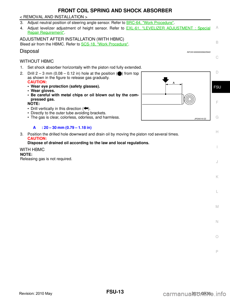
2. Drill 2 – 3 mm (0.08 – 0.12 in) hole at the position ( ) from top
as shown in the figure to release gas gradually.
CAUTION:
Wear eye protection (safety glasses).
Wear gloves.
Be careful with metal chips or oil blown out by the com-
pressed gas.
NOTE:
Drill vertically in this direction ( ).
Directly to the outer tube avoiding brackets.
The gas is clear, colorless, odorless, and harmless.
3. Position the drilled hole downward and drain oil by moving the piston rod several times. CAUTION:
Dispose of drained oil according to the law and local regulations.
WITH HBMC
NOTE:
Releasing gas is not required.A : 20 – 30 mm (0.79 – 1.18 in)
JPEIA0161ZZ
Revision: 2010 May2011 QX56
Page 2956 of 5598
FSU-14
< REMOVAL AND INSTALLATION >
LOWER LINK
LOWER LINK
Exploded ViewINFOID:0000000006225646
Removal and InstallationINFOID:0000000006225647
REMOVAL
1. Remove tires with power tool. Refer to WT-64, "Removal and Installation".
2. Remove brake hose bracket from steering knuckle. Refer to BR-23, "
FRONT : Removal and Installation".
3. Remove caliper assembly mounting bolts. Hang caliper assembly in a place where it will not interfere with work. Refer to BR-37, "
BRAKE CALIPER ASSEMBLY : Removal and Installation".
CAUTION:
Never depress brake pedal while brake caliper is removed.
4. Remove disc rotor. Refer to FA X - 8 , "
Removal and Installation" (2WD), FAX-18, "Removal and Installation"
(4WD).
5. Remove wheel sensor and harness connector. Refer to BRC-134, "
FRONT WHEEL SENSOR : Removal
and Installation".
CAUTION:
Never pull on wheel sensor harness.
6. Remove steering outer socket fr om steering knuckle. Refer to ST-42, "
Removal and Installation".
7. Remove height sensor from upper link (right side). Refer to EXL-136, "
Removal and Installation".
8. Set suitable jack under lower link.
9. Remove stabilizer connecting rod from lower link. (Without HBMC) Refer to FSU-20, "
Removal and Instal-
lation".
10. Remove shock absorber mounting bolt from lower link.
11. Separate upper link from steering knuckle. Refer to FSU-17, "
Removal and Installation".
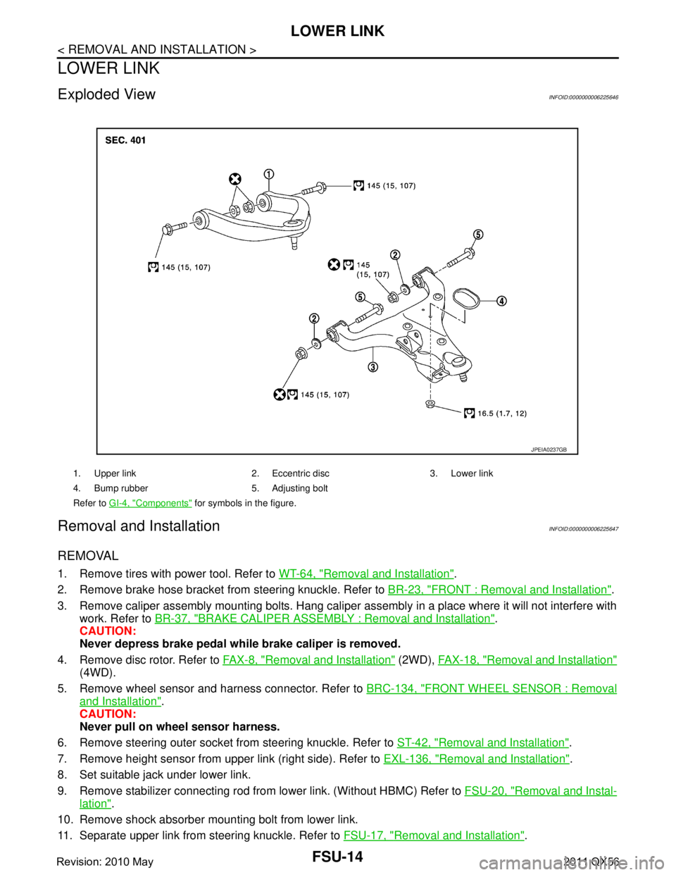
1. Upper link 2. Eccentric disc 3. Lower link
4. Bump rubber 5. Adjusting bolt
Refer to GI-4, "
Components" for symbols in the figure.
JPEIA0237GB
Revision: 2010 May2011 QX56
Page 2958 of 5598
FSU-16
< REMOVAL AND INSTALLATION >
LOWER LINK
2. Move tip of ball stud in axial direction to check for looseness.
If axial end play exceeds standard range, replace lower link assembly.
INSPECTION AFTER INSTALLATION
1. Check wheel sensor harness for proper connection. Refer to BRC-134, "FRONT WHEEL SENSOR :
Exploded View".
2. Check wheel alignment. Refer to FSU-7, "
Inspection".
3. Adjust neutral position of steering angle sensor. Refer to BRC-64, "
Work Procedure".
4. Adjust levelizer adjustment of height sensor. Refer to EXL-61, "
LEVELIZER ADJUSTMENT : Special
Repair Requirement".
Axial end play : Refer to
FSU-21, "
Ball Joint".
Revision: 2010 May2011 QX56
Page 2959 of 5598
UPPER LINKFSU-17
< REMOVAL AND INSTALLATION >
C
DF
G H
I
J
K L
M A
B
FSU
N
O P
UPPER LINK
Exploded ViewINFOID:0000000006225649
Removal and InstallationINFOID:0000000006225650
REMOVAL
1. Remove tires with power tool. Refer to WT-64, "Removal and Installation".
2. Remove brake hose bracket from steering knuckle. Refer to BR-23, "
FRONT : Removal and Installation".
3. Remove caliper assembly mounting bolts. Hang caliper assembly in a place where it will not interfere with work. Refer to BR-37, "
BRAKE CALIPER ASSEMBLY : Removal and Installation".
CAUTION:
Never depress brake pedal while brake caliper is removed.
4. Remove disc rotor. Refer to FA X - 8 , "
Removal and Installation" (2WD), FAX-18, "Removal and Installation"
(4WD).
5. Remove wheel sensor and harness connector. Refer to BRC-134, "
FRONT WHEEL SENSOR : Removal
and Installation".
CAUTION:
Never pull on wheel sensor harness.
6. Remove height sensor from upper link (right side). Refer to EXL-136, "
Removal and Installation".
7. Set suitable jack under lower link.
8. Separate upper link from steering knuckle. Refer to FA X - 8 , "
Removal and Installation" (2WD), FAX-18,
"Removal and Installation" (4WD).
9. Remove upper link mounting bolts, nuts, and upper link from vehicle.
10. Perform inspection after removal. Refer to FSU-18, "
Inspection".
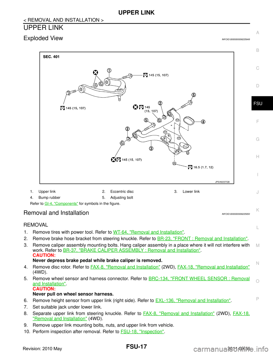
1. Upper link 2. Eccentric disc 3. Lower link
4. Bump rubber 5. Adjusting bolt
Refer to GI-4, "
Components" for symbols in the figure.
JPEIA0237GB
Revision: 2010 May2011 QX56
Page 2961 of 5598
UPPER LINKFSU-19
< REMOVAL AND INSTALLATION >
C
DF
G H
I
J
K L
M A
B
FSU
N
O P
4. Adjust levelizer adjustment of height sensor. Refer to EXL-61, "LEVELIZER ADJUSTMENT : Special
Repair Requirement".
Revision: 2010 May2011 QX56
Page 2963 of 5598
SERVICE DATA AND SPECIFICATIONS (SDS)
FSU-21
< SERVICE DATA AND SPECIFICATIONS (SDS)
C
D F
G H
I
J
K L
M A
B
FSU
N
O P
SERVICE DATA AND SPECIFICATIONS (SDS)
SERVICE DATA AND SPECIFICATIONS (SDS)
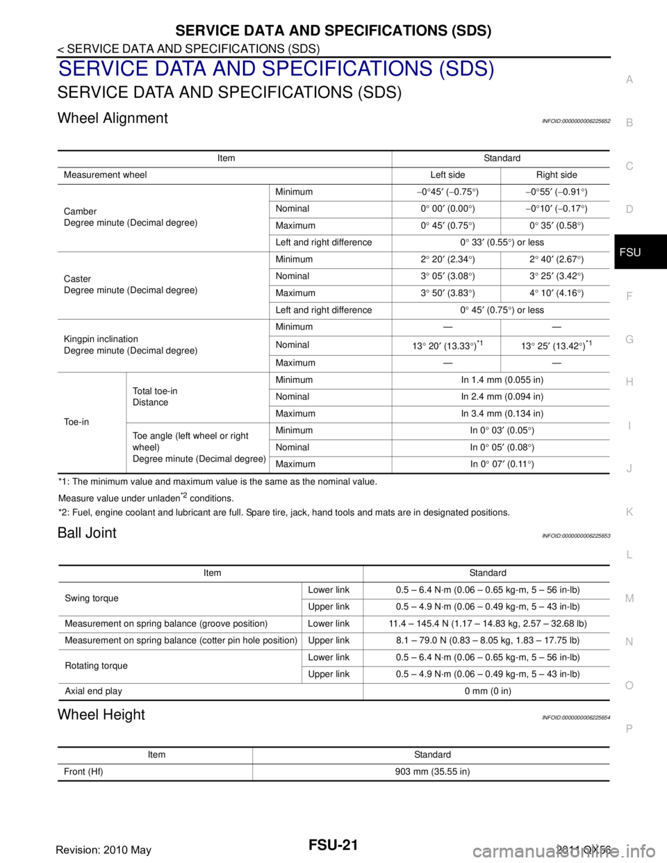
Wheel AlignmentINFOID:0000000006225652
*1: The minimum value and maximum value is the same as the nominal value.
Measure value under unladen
*2 conditions.
*2: Fuel, engine coolant and lubricant are full. Spare tire, jack, hand tools and mats are in designated positions.
Ball JointINFOID:0000000006225653
Wheel HeightINFOID:0000000006225654
Item Standard
Measurement wheel Left side Right side
Camber
Degree minute (Decimal degree) Minimum
−0 °45 ′ ( −0.75 °) −0°55 ′ ( −0.91 °)
Nominal 0 ° 00 ′ (0.00 °) −0°10 ′ ( −0.17 °)
Maximum 0 ° 45 ′ (0.75 °)0 ° 35 ′ (0.58 °)
Left and right difference 0 ° 33 ′ (0.55 °) or less
Caster
Degree minute (Decimal degree) Minimum 2
° 20 ′ (2.34 °)2 ° 40 ′ (2.67 °)
Nominal 3 ° 05 ′ (3.08 °)3 ° 25 ′ (3.42 °)
Maximum 3 ° 50 ′ (3.83 °)4 ° 10 ′ (4.16
° )
Left and right difference 0 ° 45 ′ (0.75 °) or less
Kingpin inclination
Degree minute (Decimal degree) Minimum — —
Nominal
13° 20 ′ (13.33 °)
*113 ° 25 ′ (13.42 °)*1
Maximum — —
To e - i n To t a l t o e - i n
Distance
Minimum In 1.4 mm (0.055 in)
Nominal In 2.4 mm (0.094 in)
Maximum In 3.4 mm (0.134 in)
Toe angle (left wheel or right
wheel)
Degree minute (Decimal degree) Minimum In 0
° 03 ′ (0.05 °)
Nominal In 0 ° 05 ′ (0.08 °)
Maximum In 0 ° 07 ′ (0.11 °)
Item Standard
Swing torque Lower link 0.5 – 6.4 N·m (0.06 – 0.65 kg-m, 5 – 56 in-lb)
Upper link 0.5 – 4.9 N·m (0.06 – 0.49 kg-m, 5 – 43 in-lb)
Measurement on spring balance (groove position) Lower link 11.4 – 145.4 N (1.17 – 14.83 kg, 2.57 – 32.68 lb)
Measurement on spring balance (cotter pin hole position) Upper link 8.1 – 79.0 N (0.83 – 8.05 kg, 1.83 – 17.75 lb)
Rotating torque Lower link 0.5 – 6.4 N·m (0.06 – 0.65 kg-m, 5 – 56 in-lb)
Upper link 0.5 – 4.9 N·m (0.06 – 0.49 kg-m, 5 – 43 in-lb)
Axial end play 0 mm (0 in)
Item Standard
Front (Hf) 903 mm (35.55 in)
Revision: 2010 May2011 QX56
Page 2989 of 5598
IDENTIFICATION INFORMATIONGI-25
< VEHICLE INFORMATION >
C
DE
F
G H
I
J
K L
M B
GI
N
O P
DimensionsINFOID:0000000006280863
Unit: mm (in)
Wheels & TiresINFOID:0000000006280864
: Vehicle front
JPAIA0770ZZ
Overall length 5,290 (208.3)
Overall width 2,030 (79.9)
Overall height 1,925 (75.8)
Front tread 1,715 (67.5)
Rear tread 1,725 (67.9)
Wheelbase 3,075 (121.1)
ConventionalTire
20 inch P275/60R20 114H
22 inch P275/50R22 111H
Road wheel 20 inch
(Aluminum)
Size 20
× 8J
Offset 30 mm (1.18 in)
22 inch
(Aluminum) Size 22
× 8J
Offset 30 mm (1.18 in)
Spare Tire
20 inch P275/60R20 114H
22 inch P275/50R22 111H
Road wheel 20 inch
(Aluminum)
Size 20
× 8J
Offset 30 mm (1.18 in)
22 inch
(Aluminum) Size 22
× 8J
Offset 30 mm (1.18 in)
Revision: 2010 May2011 QX56
Page 3813 of 5598
MWI-70
< DTC/CIRCUIT DIAGNOSIS >
FUEL LEVEL SENSOR SIGNAL CIRCUIT
Is the inspection result normal?
YES >> GO TO 3.
NO >> Repair harness or connector.
3.CHECK FUEL LEVEL SENSOR GROUND CIRCUIT
Check continuity between fuel level sensor unit harness connector and combination meter harness connector.
Is the inspection result normal?
YES >> INSPECTION END
NO >> Repair harness or connector.
Component InspectionINFOID:0000000006221750
1.REMOVE FUEL LEVEL SENSOR UNIT
Remove the fuel level sensor unit. Refer to FL-5, "
Removal and Installation".
>> GO TO 2.
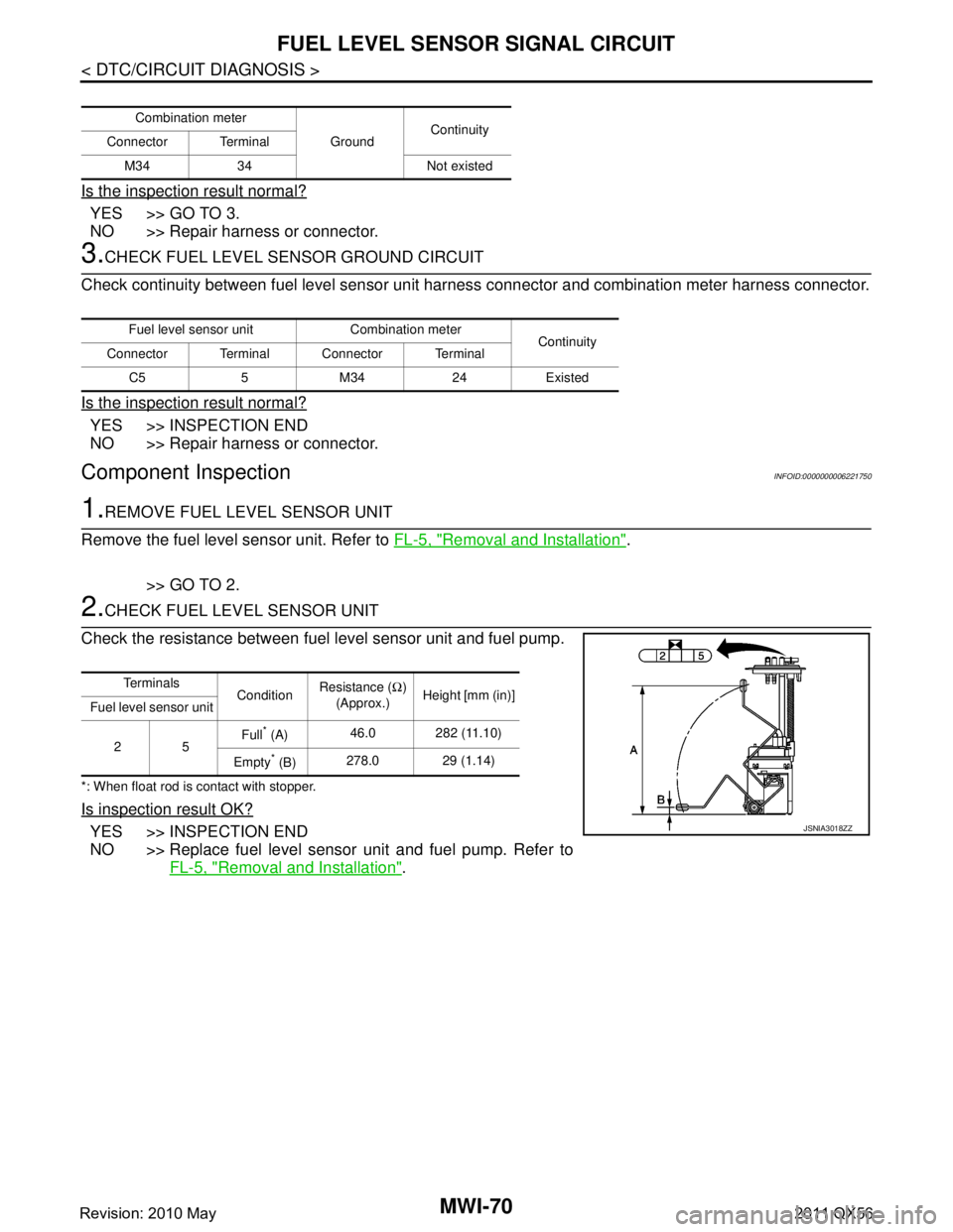
2.CHECK FUEL LEVEL SENSOR UNIT
Check the resistance between fuel level sensor unit and fuel pump.
*: When float rod is contact with stopper.
Is inspection result OK?
YES >> INSPECTION END
NO >> Replace fuel level sensor unit and fuel pump. Refer to FL-5, "
Removal and Installation".
Combination meter
GroundContinuity
Connector Terminal
M34 34 Not existed
Fuel level sensor unit Combination meter Continuity
Connector Terminal Connector Terminal
C5 5 M34 24 Existed
Te r m i n a l s ConditionResistance (
Ω)
(Approx.) Height [mm (in)]
Fuel level sensor unit
25 Full
* (A)
46.0 282 (11.10)
Empty
* (B) 278.0 29 (1.14)
JSNIA3018ZZ
Revision: 2010 May2011 QX56