2011 INFINITI QX56 sensor
[x] Cancel search: sensorPage 4772 of 5598
COLLISION DIAGNOSISSR-9
< BASIC INSPECTION >
C
DE
F
G
I
J
K L
M A
B
SR
N
O P
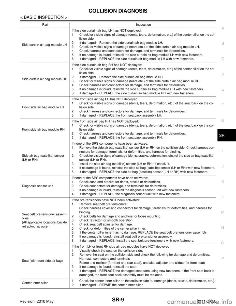
Part Inspection
Side curtain air bag module LH If the side curtain air bag LH has NOT deployed:
1. Check for visible signs of damage (dents, tears, deformation, etc.) of the center pillar on the col-
lision side.
2. If damaged − Remove the side curtain air bag module LH.
3. Check for visible signs of damage (tears etc.) of the side curtain air bag module LH.
4. Check harness and connectors for damage, and terminals for deformities.
5. If no damage is found, reinstall the side curtain air bag module LH with new fasteners.
6. If damaged − REPLACE the side curtain air bag module LH with new fasteners.
Side curtain air bag module RH If the side curtain air bag RH has NOT deployed:
1. Check for visible signs of damage (dents, tears, deformation, etc.) of the center pillar on the col-
lision side.
2. If damaged − Remove the side curtain air bag module RH.
3. Check for visible signs of damage (tears etc.) of the side curtain air bag module RH.
4. Check harness and connectors for damage, and terminals for deformities.
5. If no damage is found, reinstall the side curtain air bag module RH with new fasteners.
6. If damaged − REPLACE the side curtain air bag module RH with new fasteners.
Front side air bag module LH If the front side air bag LH has NOT deployed:
1. Check for visible signs of damage (dents, tears, deformation, etc.) of the seat back on the col-
lision side.
2. Check harness and connectors for damage, and terminals for deformities.
3. If damaged − REPLACE the front seatback assembly LH.
Front side air bag module RH If the front side air bag RH has NOT deployed:
1. Check for visible signs of damage (dents, tears, deformation, etc.) of the seat back on the col-
lision side.
2. Check harness and connectors for damage, and terminals for deformities.
3. If damaged − REPLACE the front seatback assembly RH.
Side air bag (satellite) sensor
(LH or RH) If none of the SRS components have been activated:
1. Remove the side air bag (satellite) sensor (LH or RH) on the collision side. Check harness con-
nectors for damage, terminals for deformities, and harness for binding.
2. Check for visible signs of damage (dents, cracks, deformation, etc.) of the side air bag (satellite)
sensor (LH or RH).
3. Install the side air bag (satellite) sensor (LH or RH) to check fit.
4. If no damage is found, reinstall the side sir bag (satellite) sensor (LH or RH) with new fasteners.
5. If damaged − REPLACE the side air bag (satellite) sensor (LH or RH) with new fasteners.
Diagnosis sensor unit If none of the SRS components have been activated:
1. Check case and bracket for dents, cracks or deformities.
2. Check connectors for damage, and terminals for deformities.
3. If no damage is found, reinstall the diagnosis sensor unit with new fasteners.
4. If damaged
− REPLACE the diagnosis sensor unit with new fasteners.
Seat belt pre-tensioner assem-
blies
(All applicable locations: buckle,
retractor, lap outer) If the pre-tensioners have NOT been activated:
1. Remove seat belt pre-tensioners.
Check harness cover and connectors for damage, terminals for deformities, and harness for
binding.
2. Check belts for damage and anchors for loose mounting.
3. Check retractor for smooth operation.
4. Check seat belt adjuster for damage.
5. Check for deformities of the center pillar inner.
6. If the center pillar inner has no damage, REPLACE the seat belt pre-tensioner assembly.
7. If no damage is found, reinstall seat belt pre-tensioner assembly.
8. If damaged − REPLACE. Install the seat belt pre-tensioners with new fasteners.
Seat (with front side air bag) If the front LH or front RH side air bag modules have NOT deployed:
1. Visually check the seat on the collision side.
2. Remove the seat on the collision side and check the following for damage and deformities.
- Harness, connectors and terminals
- Frame and recliner (for front and rear seat), and also adjuster and slides (for front seat)
3. If no damage is found, reinstall the seat.
4. If damaged
− REPLACE the damaged seat parts using new fasteners. If the front seat back is
damaged, the front seat back assembly must be replaced.
Center inner pillar 1. Check the center inner pillar on the collision side for damage (dents, cracks, deformation, etc.).
2. If damaged
− REPAIR the center inner pillar.
Revision: 2010 May2011 QX56
Page 4774 of 5598
DRIVER AIR BAG MODULESR-11
< REMOVAL AND INSTALLATION >
C
DE
F
G
I
J
K L
M A
B
SR
N
O P
REMOVAL AND INSTALLATION
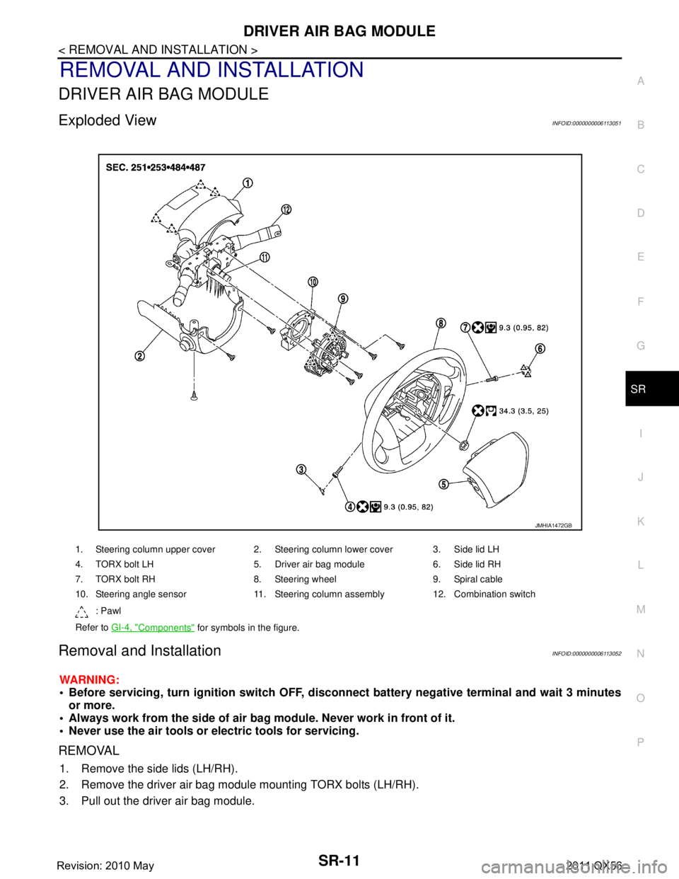
DRIVER AIR BAG MODULE
Exploded ViewINFOID:0000000006113051
Removal and InstallationINFOID:0000000006113052
WARNING:
Before servicing, turn ignition switch OFF, disconnect battery ne gative terminal and wait 3 minutes
or more.
Always work from the side of air bag module. Never work in front of it.
Never use the air tools or el ectric tools for servicing.
REMOVAL
1. Remove the side lids (LH/RH).
2. Remove the driver air bag module mounting TORX bolts (LH/RH).
3. Pull out the driver air bag module.
1. Steering column upper cover 2. Steering column lower cover 3. Side lid LH
4. TORX bolt LH 5. Driver air bag module 6. Side lid RH
7. TORX bolt RH 8. Steering wheel 9. Spiral cable
10. Steering angle sensor 11. Steering column assembly 12. Combination switch
: Pawl
Refer to GI-4, "
Components" for symbols in the figure.
JMHIA1472GB
Revision: 2010 May2011 QX56
Page 4777 of 5598
SR-14
< REMOVAL AND INSTALLATION >
SPIRAL CABLE
SPIRAL CABLE
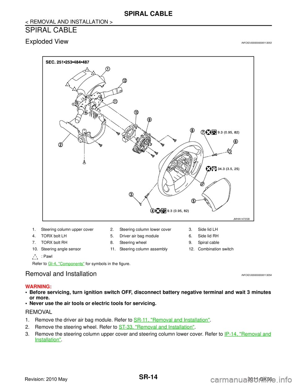
Exploded ViewINFOID:0000000006113053
Removal and InstallationINFOID:0000000006113054
WARNING:
Before servicing, turn ignition switch OFF, disconnect battery ne gative terminal and wait 3 minutes
or more.
Never use the air tools or electric tools for servicing.
REMOVAL
1. Remove the driver air bag module. Refer to SR-11, "Removal and Installation".
2. Remove the steering wheel. Refer to ST-33, "
Removal and Installation".
3. Remove the steering column upper cover and steering column lower cover. Refer to IP-14, "
Removal and
Installation".
1. Steering column upper cover 2. Steering column lower cover 3. Side lid LH
4. TORX bolt LH 5. Driver air bag module 6. Side lid RH
7. TORX bolt RH 8. Steering wheel 9. Spiral cable
10. Steering angle sensor 11. Steering column assembly 12. Combination switch
: Pawl
Refer to GI-4, "
Components" for symbols in the figure.
JMHIA1472GB
Revision: 2010 May2011 QX56
Page 4778 of 5598
SPIRAL CABLESR-15
< REMOVAL AND INSTALLATION >
C
DE
F
G
I
J
K L
M A
B
SR
N
O P
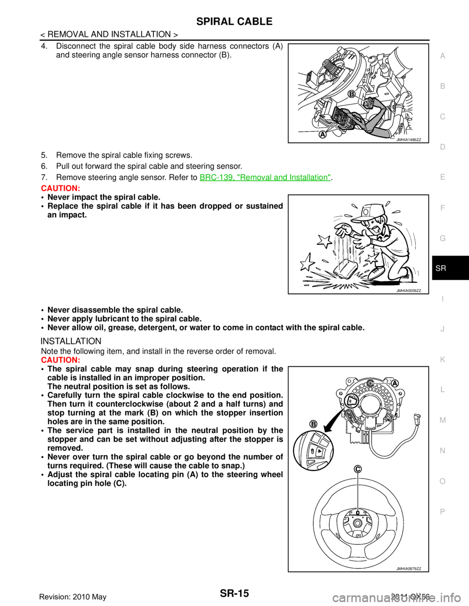
4. Disconnect the spiral cable body side harness connectors (A) and steering angle sensor harness connector (B).
5. Remove the spiral cable fixing screws.
6. Pull out forward the spiral cable and steering sensor.
7. Remove steering angle sensor. Refer to BRC-139, "
Removal and Installation".
CAUTION:
Never impact the spiral cable.
Replace the spiral cable if it has been dropped or sustained
an impact.
Never disassemble the spiral cable.
Never apply lubricant to the spiral cable.
Never allow oil, grease, detergent, or water to come in contact with the spiral cable.
INSTALLATION
Note the following item, and install in the reverse order of removal.
CAUTION:
The spiral cable may snap during steering operation if the
cable is installed in an improper position.
The neutral position is set as follows.
Carefully turn the spiral cable clockwise to the end position.
Then turn it counterclockwise (a bout 2 and a half turns) and
stop turning at the mark (B) on which the stopper insertion
holes are in the same position.
The service part is installed in the neutral position by the
stopper and can be set without adjusting after the stopper is
removed.
Never over turn the spiral cable or go beyond the number of
turns required. (These will cause the cable to snap.)
Adjust the spiral cable locatin g pin (A) to the steering wheel
locating pin hole (C).
JMHIA1486ZZ
JMHIA0009ZZ
JMHIA0879ZZ
Revision: 2010 May2011 QX56
Page 4785 of 5598
SR-22
< REMOVAL AND INSTALLATION >
CRASH ZONE SENSOR
CRASH ZONE SENSOR
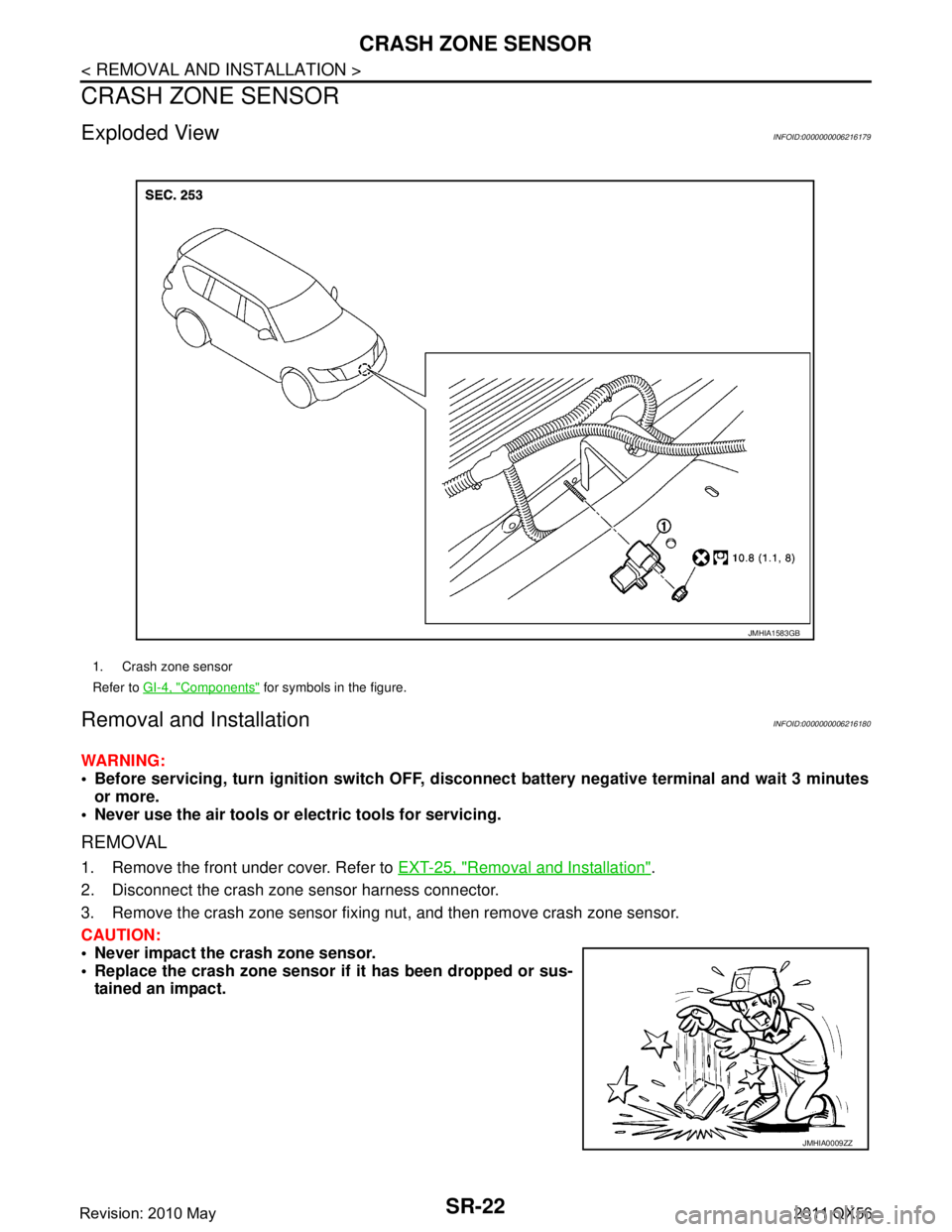
Exploded ViewINFOID:0000000006216179
Removal and InstallationINFOID:0000000006216180
WARNING:
Before servicing, turn ignition switch OFF, disconnect battery ne gative terminal and wait 3 minutes
or more.
Never use the air tools or electric tools for servicing.
REMOVAL
1. Remove the front under cover. Refer to EXT-25, "Removal and Installation".
2. Disconnect the crash zone sensor harness connector.
3. Remove the crash zone sensor fixing nut, and then remove crash zone sensor.
CAUTION:
Never impact the crash zone sensor.
Replace the crash zone sensor if it has been dropped or sus-
tained an impact.
1. Crash zone sensor
Refer to GI-4, "
Components" for symbols in the figure.
JMHIA1583GB
JMHIA0009ZZ
Revision: 2010 May2011 QX56
Page 4786 of 5598
CRASH ZONE SENSORSR-23
< REMOVAL AND INSTALLATION >
C
DE
F
G
I
J
K L
M A
B
SR
N
O P
Replace the crash zone sensor of deployed driver air bag and deployed front passenger air bag.
INSTALLATION
Note the following item, and install in the reverse order of removal.
CAUTION:
Never use the old fixing nut afte r removal, replace with the new nut.
Never damage the harness co nnector while installing.
If malfunction is detected by the air bag warnin g lamp, after repair or replacement of the malfunc-
tioning parts, reset the memory using sel f-diagnosis or CONSULT-III. Refer to SRC-14, "
On Board
Diagnosis Function" or SRC-19, "CONSULT-III Function".
After the work is completed, check that no system malfunction is detected by air bag warning lamp.
Revision: 2010 May2011 QX56
Page 4787 of 5598
SR-24
< REMOVAL AND INSTALLATION >
SIDE AIR BAG (SATELLITE) SENSOR
SIDE AIR BAG (SATELLITE) SENSOR
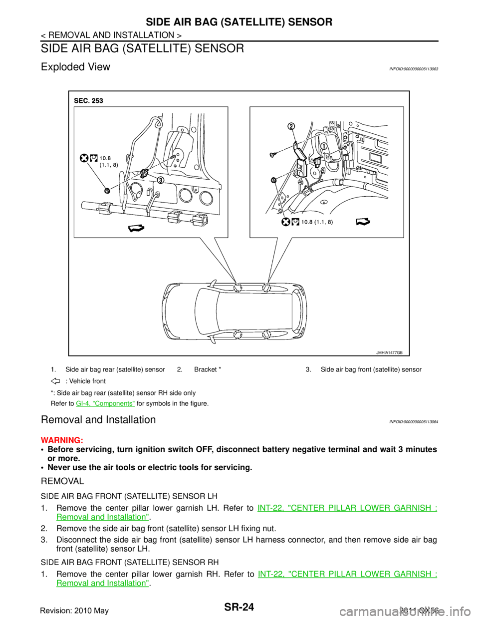
Exploded ViewINFOID:0000000006113063
Removal and InstallationINFOID:0000000006113064
WARNING:
Before servicing, turn ignition switch OFF, disconnect battery ne gative terminal and wait 3 minutes
or more.
Never use the air tools or electric tools for servicing.
REMOVAL
SIDE AIR BAG FRONT (SATELLITE) SENSOR LH
1. Remove the center pillar lower garnish LH. Refer to INT-22, "CENTER PILLAR LOWER GARNISH :
Removal and Installation".
2. Remove the side air bag front (satellite) sensor LH fixing nut.
3. Disconnect the side air bag front (satellite) sensor LH harness connector, and then remove side air bag
front (satellite) sensor LH.
SIDE AIR BAG FRONT (SATELLITE) SENSOR RH
1. Remove the center pillar lower garnish RH. Refer to INT-22, "CENTER PILLAR LOWER GARNISH :
Removal and Installation".
1. Side air bag rear (satellite) sensor 2. Bracket * 3. Side air bag front (satellite) sensor
: Vehicle front
*: Side air bag rear (satellite) sensor RH side only
Refer to GI-4, "
Components" for symbols in the figure.
JMHIA1477GB
Revision: 2010 May2011 QX56
Page 4788 of 5598
SIDE AIR BAG (SATELLITE) SENSOR
SR-25
< REMOVAL AND INSTALLATION >
C
D E
F
G
I
J
K L
M A
B
SR
N
O P
2. Remove the front seat belt retractor. Refer to SB-6, "SEAT BELT RETRACTOR : Removal and Installa-
tion".
3. Remove the side air bag front (satellite) sensor RH fixing nut.
4. Disconnect the side air bag front (satellite) sens or RH harness connector, and then remove side air bag
front (satellite) sensor RH.
SIDE AIR BAG REAR (SATELLITE) SENSOR LH
1. Remove the luggage side lower finisher LH. Refer to INT-36, "LUGGAGE SIDE LOWER FINISHER :
Removal and Installation".
2. Remove the side air bag rear (satellite) sensor LH fixing nut.
3. Disconnect the side air bag rear (satellite) sensor LH harness connector, and then remove side air bag
rear (satellite) sensor LH.
SIDE AIR BAG REAR (SATELLITE) SENSOR RH
1. Remove the luggage side lower finisher RH. Refer to INT-36, "LUGGAGE SIDE LOWER FINISHER :
Removal and Installation".
2. Remove the shield bracket fixing screw, and then remove shield bracket.
3. Remove the side air bag rear (satellite) sensor RH fixing nut.
4. Disconnect the side air bag rear (satellite) sensor RH harness connector, and then remove side air bag rear (satellite) sensor RH.
CAUTION:
Never impact the side air bag (satellite) sensor.
Replace the side air bag (sat ellite) sensor if it has been
dropped or sustained an impact.
Replace the satellite sensor of deployed front side air bag module and deployed side curtain air bag
module.
INSTALLATION
Note the following item, and install in the reverse order of removal.
CAUTION:
Never use the old fixing nut afte r removal, replace with the new nut.
Never damage the harness connector while installing
If malfunction is detected by the air bag warnin g lamp, after repair or replacement of the malfunc-
tioning parts, reset the memory using sel f-diagnosis or CONSULT-III. Refer to SRC-14, "
On Board
Diagnosis Function" or SRC-19, "CONSULT-III Function".
After the work is completed, check that no system malfunction is detected by air bag warning lamp.
JMHIA0009ZZ
Revision: 2010 May2011 QX56