2011 INFINITI QX56 sensor
[x] Cancel search: sensorPage 4536 of 5598
SEATBACK THERMAL ELECTRIC UNIT SENSORSE-77
< DTC/CIRCUIT DIAGNOSIS >
C
DE
F
G H
I
K L
M A
B
SE
N
O P
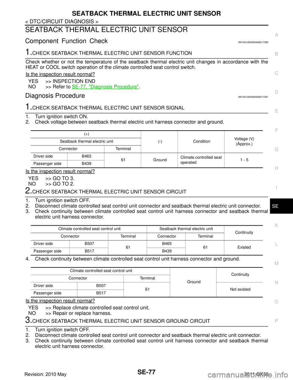
SEATBACK THERMAL ELECTRIC UNIT SENSOR
Component Function CheckINFOID:0000000006217396
1.CHECK SEATBACK THERMAL ELECTRIC UNIT SENSOR FUNCTION
Check whether or not the temperatur e of the seatback thermal electric unit changes in accordance with the
HEAT or COOL switch operation of the climate controlled seat control switch.
Is the inspection result normal?
YES >> INSPECTION END
NO >> Refer to SE-77, "
Diagnosis Procedure".
Diagnosis ProcedureINFOID:0000000006217397
1.CHECK SEATBACK THERMAL ELECTRIC UNIT SENSOR SIGNAL
1. Turn ignition switch ON.
2. Check voltage between seatback thermal electric unit harness connector and ground.
Is the inspection result normal?
YES >> GO TO 3.
NO >> GO TO 2.
2.CHECK SEATBACK THERMAL ELECTRIC UNIT SENSOR CIRCUIT
1. Turn ignition switch OFF.
2. Disconnect climate controlled seat control unit c onnector and seatback thermal electric unit connector.
3. Check continuity between climate controlled s eat control unit harness connector and seatback thermal
electric unit harness connector.
4. Check continuity between climate controll ed seat control unit harness connector and ground.
Is the inspection result normal?
YES >> Replace climate controlled seat control unit.
NO >> Repair or replace harness.
3.CHECK SEATBACK THERMAL ELECTRIC UNIT SENSOR GROUND CIRCUIT
1. Turn ignition switch OFF.
2. Disconnect climate controlled seat control unit c onnector and seatback thermal electric unit connector.
3. Check continuity between climate controlled s eat control unit harness connector and seatback thermal
electric unit harness connector.
(+)
(-) Condition Voltage (V)
(Approx.)
Seatback thermal electric unit
Connector Terminal
Driver side B465 61 GroundClimate controlled seat
operated
1 - 5
Passenger side B439
Climate controlled seat control unit Seatback thermal electric unit Continuity
Connector Terminal Connector Terminal
Driver side B507 61B465
61 Existed
Passenger side B517 B439
Climate controlled seat control unit GroundContinuity
Connector Terminal
Driver side B507 61 Not existed
Passenger side B517
Revision: 2010 May2011 QX56
Page 4537 of 5598
SE-78
< DTC/CIRCUIT DIAGNOSIS >
SEATBACK THERMAL ELECTRIC UNIT SENSOR
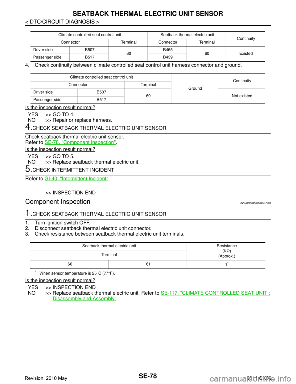
4. Check continuity between climate controlled seat control unit harness connector and ground.
Is the inspection result normal?
YES >> GO TO 4.
NO >> Repair or replace harness.
4.CHECK SEATBACK THERMAL ELECTRIC UNIT SENSOR
Check seatback thermal electric unit sensor.
Refer to SE-78, "
Component Inspection".
Is the inspection result normal?
YES >> GO TO 5.
NO >> Replace seatback thermal electric unit.
5.CHECK INTERMITTENT INCIDENT
Refer to GI-40, "
Intermittent Incident".
>> INSPECTION END
Component InspectionINFOID:0000000006217398
1.CHECK SEATBACK THERMAL ELECTRIC UNIT SENSOR
1. Turn ignition switch OFF.
2. Disconnect seatback thermal electric unit connector.
3. Check resistance between seatback thermal electric unit terminals.
* : When sensor temperature is 25 °C (77 °F).
Is the inspection result normal?
YES >> INSPECTION END
NO >> Replace seatback thermal electric unit. Refer to SE-117, "
CLIMATE CONTROLLED SEAT UNIT :
Disassembly and Assembly".
Climate controlled seat control unit Seatback thermal electric unit
Continuity
Connector Terminal Connector Terminal
Driver side B507 60B465
60 Existed
Passenger side B517 B439
Climate controlled seat control unit GroundContinuity
Connector Terminal
Driver side B507 60 Not existed
Passenger side B517
Seatback thermal electric unit Resistance
(KΩ)
(Approx.)
Te r m i n a l
60 61 1
*
Revision: 2010 May2011 QX56
Page 4540 of 5598
SEAT CUSHION THERMAL ELECTRIC UNIT SENSORSE-81
< DTC/CIRCUIT DIAGNOSIS >
C
DE
F
G H
I
K L
M A
B
SE
N
O P
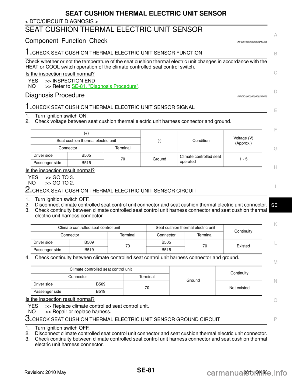
SEAT CUSHION THERMAL ELECTRIC UNIT SENSOR
Component Function CheckINFOID:0000000006217401
1.CHECK SEAT CUSHION THERMAL ELECTRIC UNIT SENSOR FUNCTION
Check whether or not the temperature of the seat cush ion thermal electric unit changes in accordance with the
HEAT or COOL switch operation of the climate controlled seat control switch.
Is the inspection result normal?
YES >> INSPECTION END
NO >> Refer to SE-81, "
Diagnosis Procedure".
Diagnosis ProcedureINFOID:0000000006217402
1.CHECK SEAT CUSHION THERMAL ELECTRIC UNIT SENSOR SIGNAL
1. Turn ignition switch ON.
2. Check voltage between seat cushion ther mal electric unit harness connector and ground.
Is the inspection result normal?
YES >> GO TO 3.
NO >> GO TO 2.
2.CHECK SEAT CUSHION THERMAL ELECTRIC UNIT SENSOR CIRCUIT
1. Turn ignition switch OFF.
2. Disconnect climate controlled seat control unit connec tor and seat cushion thermal electric unit connector.
3. Check continuity between climate controlled seat control unit harness connector and seat cushion thermal
electric unit harness connector.
4. Check continuity between climate controll ed seat control unit harness connector and ground.
Is the inspection result normal?
YES >> Replace climate controlled seat control unit.
NO >> Repair or replace harness.
3.CHECK SEAT CUSHION THERMAL ELEC TRIC UNIT SENSOR GROUND CIRCUIT
1. Turn ignition switch OFF.
2. Disconnect climate controlled seat control unit connec tor and seat cushion thermal electric unit connector.
3. Check continuity between climate controlled seat control unit harness connector and seat cushion thermal
electric unit harness connector.
(+)
(-) Condition Voltage (V)
(Approx.)
Seat cushion thermal electric unit
Connector Terminal
Driver side B505 70 GroundClimate controlled seat
operated
1 - 5
Passenger side B515
Climate controlled seat control unit Seat cushion thermal electric unit Continuity
Connector Terminal Connector Terminal
Driver side B509 70B505
70 Existed
Passenger side B519 B515
Climate controlled seat control unit GroundContinuity
Connector Terminal
Driver side B509 70 Not existed
Passenger side B519
Revision: 2010 May2011 QX56
Page 4541 of 5598
SE-82
< DTC/CIRCUIT DIAGNOSIS >
SEAT CUSHION THERMAL ELECTRIC UNIT SENSOR
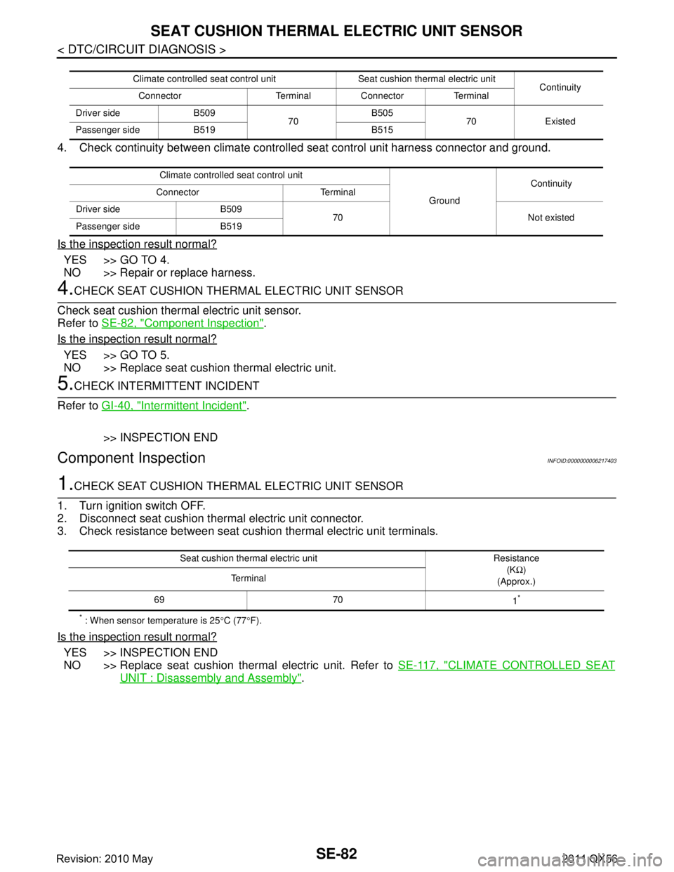
4. Check continuity between climate controlled seat control unit harness connector and ground.
Is the inspection result normal?
YES >> GO TO 4.
NO >> Repair or replace harness.
4.CHECK SEAT CUSHION THERMAL ELECTRIC UNIT SENSOR
Check seat cushion thermal electric unit sensor.
Refer to SE-82, "
Component Inspection".
Is the inspection result normal?
YES >> GO TO 5.
NO >> Replace seat cushion thermal electric unit.
5.CHECK INTERMITTENT INCIDENT
Refer to GI-40, "
Intermittent Incident".
>> INSPECTION END
Component InspectionINFOID:0000000006217403
1.CHECK SEAT CUSHION THERMAL ELECTRIC UNIT SENSOR
1. Turn ignition switch OFF.
2. Disconnect seat cushion thermal electric unit connector.
3. Check resistance between seat cushion thermal electric unit terminals.
* : When sensor temperature is 25 °C (77 °F).
Is the inspection result normal?
YES >> INSPECTION END
NO >> Replace seat cushion thermal electric unit. Refer to SE-117, "
CLIMATE CONTROLLED SEAT
UNIT : Disassembly and Assembly".
Climate controlled seat control unit Seat cushion thermal electric unit
Continuity
Connector Terminal Connector Terminal
Driver side B509 70B505
70 Existed
Passenger side B519 B515
Climate controlled seat control unit GroundContinuity
Connector Terminal
Driver side B509 70 Not existed
Passenger side B519
Seat cushion thermal electric unit Resistance
(KΩ)
(Approx.)
Te r m i n a l
69 70 1
*
Revision: 2010 May2011 QX56
Page 4553 of 5598
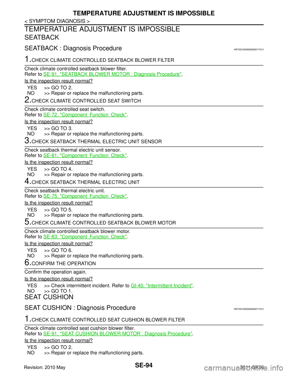
SE-94
< SYMPTOM DIAGNOSIS >
TEMPERATURE ADJUSTMENT IS IMPOSSIBLE
TEMPERATURE ADJUSTMENT IS IMPOSSIBLE
SEATBACK
SEATBACK : Diagnosis ProcedureINFOID:0000000006217413
1.CHECK CLIMATE CONTROLLED SEATBACK BLOWER FILTER
Check climate controlled seatback blower filter.
Refer to SE-91, "
SEATBACK BLOWER MOTOR : Diagnosis Procedure".
Is the inspection result normal?
YES >> GO TO 2.
NO >> Repair or replace the malfunctioning parts.
2.CHECK CLIMATE CONTROLLED SEAT SWITCH
Check climate controlled seat switch.
Refer to SE-72, "
ComponentFunctionCheck".
Is the inspection result normal?
YES >> GO TO 3.
NO >> Repair or replace the malfunctioning parts.
3.CHECK SEATBACK THERMAL ELECTRIC UNIT SENSOR
Check seatback thermal electric unit sensor.
Refer to SE-81, "
ComponentFunctionCheck".
Is the inspection result normal?
YES >> GO TO 4.
NO >> Repair or replace the malfunctioning parts.
4.CHECK SEATBACK THERMAL ELECTRIC UNIT
Check seatback thermal electric unit.
Refer to SE-75, "
ComponentFunctionCheck".
Is the inspection result normal?
YES >> GO TO 5.
NO >> Repair or replace the malfunctioning parts.
5.CHECK CLIMATE CONTROLLED SEATBACK BLOWER MOTOR
Check climate controlled seatback blower motor.
Refer to SE-83, "
ComponentFunctionCheck".
Is the inspection result normal?
YES >> GO TO 6.
NO >> Repair or replace the malfunctioning parts.
6.CONFIRM THE OPERATION
Confirm the operation again.
Is the inspection result normal?
YES >> Check intermittent incident. Refer to GI-40, "Intermittent Incident".
NO >> GO TO 1.
SEAT CUSHION
SEAT CUSHION : Diagnosis ProcedureINFOID:0000000006217414
1.CHECK CLIMATE CONTROLLED SEAT CUSHION BLOWER FILTER
Check climate controlled seat cushion blower filter.
Refer to SE-91, "
SEAT CUSHION BLOWER MOTOR : Diagnosis Procedure".
Is the inspection result normal?
YES >> GO TO 2.
NO >> Repair or replace the malfunctioning parts.
Revision: 2010 May2011 QX56
Page 4554 of 5598
TEMPERATURE ADJUSTMENT IS IMPOSSIBLESE-95
< SYMPTOM DIAGNOSIS >
C
DE
F
G H
I
K L
M A
B
SE
N
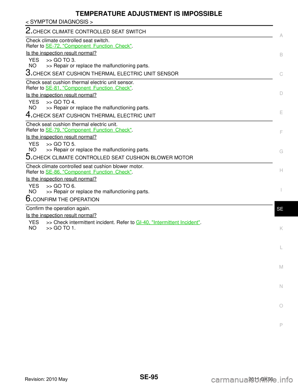
O P
2.CHECK CLIMATE CONT ROLLED SEAT SWITCH
Check climate controlled seat switch.
Refer to SE-72, "
ComponentFunctionCheck".
Is the inspection result normal?
YES >> GO TO 3.
NO >> Repair or replace the malfunctioning parts.
3.CHECK SEAT CUSHION THERMAL ELECTRIC UNIT SENSOR
Check seat cushion thermal electric unit sensor.
Refer to SE-81, "
ComponentFunctionCheck".
Is the inspection result normal?
YES >> GO TO 4.
NO >> Repair or replace the malfunctioning parts.
4.CHECK SEAT CUSHION THERMAL ELECTRIC UNIT
Check seat cushion thermal electric unit.
Refer to SE-79, "
ComponentFunctionCheck".
Is the inspection result normal?
YES >> GO TO 5.
NO >> Repair or replace the malfunctioning parts.
5.CHECK CLIMATE CONTROLLED SEA T CUSHION BLOWER MOTOR
Check climate controlled seat cushion blower motor.
Refer to SE-86, "
ComponentFunctionCheck".
Is the inspection result normal?
YES >> GO TO 6.
NO >> Repair or replace the malfunctioning parts.
6.CONFIRM THE OPERATION
Confirm the operation again.
Is the inspection result normal?
YES >> Check intermittent incident. Refer to GI-40, "Intermittent Incident".
NO >> GO TO 1.
Revision: 2010 May2011 QX56
Page 4612 of 5598
![INFINITI QX56 2011 Factory Service Manual
PRECAUTIONSSEC-5
< PRECAUTION > [WITH INTELLIGENT KEY SYSTEM]
C
D
E
F
G H
I
J
L
M A
B
SEC
N
O P
PRECAUTION
PRECAUTIONS
Precaution for Supplemental Restraint System (SRS) "AIR BAG" and "SEAT BELT
PR INFINITI QX56 2011 Factory Service Manual
PRECAUTIONSSEC-5
< PRECAUTION > [WITH INTELLIGENT KEY SYSTEM]
C
D
E
F
G H
I
J
L
M A
B
SEC
N
O P
PRECAUTION
PRECAUTIONS
Precaution for Supplemental Restraint System (SRS) "AIR BAG" and "SEAT BELT
PR](/manual-img/42/57033/w960_57033-4611.png)
PRECAUTIONSSEC-5
< PRECAUTION > [WITH INTELLIGENT KEY SYSTEM]
C
D
E
F
G H
I
J
L
M A
B
SEC
N
O P
PRECAUTION
PRECAUTIONS
Precaution for Supplemental Restraint System (SRS) "AIR BAG" and "SEAT BELT
PRE-TENSIONER"
INFOID:0000000006226148
The Supplemental Restraint System such as “A IR BAG” and “SEAT BELT PRE-TENSIONER”, used along
with a front seat belt, helps to reduce the risk or severi ty of injury to the driver and front passenger for certain
types of collision. This system includes seat belt switch inputs and dual stage front air bag modules. The SRS
system uses the seat belt switches to determine the front air bag deployment, and may only deploy one front
air bag, depending on the severity of a collision and whether the front occupants are belted or unbelted.
Information necessary to service the system safely is included in the “SRS AIR BAG” and “SEAT BELT” of this
Service Manual.
WARNING:
• To avoid rendering the SRS inoper ative, which could increase the risk of personal injury or death in
the event of a collision that would result in air ba g inflation, all maintenance must be performed by
an authorized NISSAN/INFINITI dealer.
Improper maintenance, including in correct removal and installation of the SRS, can lead to personal
injury caused by unintentional act ivation of the system. For removal of Spiral Cable and Air Bag
Module, see the “SRS AIR BAG”.
Do not use electrical test equipm ent on any circuit related to the SRS unless instructed to in this
Service Manual. SRS wiring harnesses can be identi fied by yellow and/or orange harnesses or har-
ness connectors.
PRECAUTIONS WHEN USING POWER TOOLS (AIR OR ELECTRIC) AND HAMMERS
WARNING:
When working near the Air Bag Diagnosis Sensor Unit or other Air Bag System sensors with the
ignition ON or engine running, DO NOT use air or electric power tools or strike near the sensor(s)
with a hammer. Heavy vibration could activate the sensor(s) and deploy the air bag(s), possibly
causing serious injury.
When using air or electric power tools or hammers , always switch the ignition OFF, disconnect the
battery, and wait at least 3 minutes before performing any service.
Precaution Necessary for Steering Wh eel Rotation after Battery Disconnect
INFOID:0000000006226149
NOTE:
Before removing and installing any control units, first tu rn the push-button ignition switch to the LOCK posi-
tion, then disconnect both battery cables.
After finishing work, confirm that all control unit connectors are connected properly, then re-connect both
battery cables.
Always use CONSULT-III to perform self-diagnosis as a part of each function inspection after finishing work.
If a DTC is detected, perform trouble diagnos is according to self-diagnosis results.
For vehicle with steering lock unit, if the battery is disconnected or discharged, the steering wheel will lock and
cannot be turned.
If turning the steering wheel is required with the batte ry disconnected or discharged, follow the operation pro-
cedure below before starting the repair operation.
OPERATION PROCEDURE
1. Connect both battery cables. NOTE:
Supply power using jumper cables if battery is discharged.
2. Turn the push-button ignition switch to ACC position. (At this time, the steering lock will be released.)
3. Disconnect both battery cables. The steering lock wil l remain released with both battery cables discon-
nected and the steering wheel can be turned.
4. Perform the necessary repair operation.
Revision: 2010 May2011 QX56
Page 4631 of 5598
![INFINITI QX56 2011 Factory Service Manual
SEC-24
< SYSTEM DESCRIPTION >[WITH INTELLIGENT KEY SYSTEM]
DIAGNOSIS SYSTEM (BCM)
SELF-DIAG RESULT
Refer to
BCS-57, "DTCIndex".
DATA MONITOR
PW DOWN SET Unlock button pressing time on Intelligent Ke INFINITI QX56 2011 Factory Service Manual
SEC-24
< SYSTEM DESCRIPTION >[WITH INTELLIGENT KEY SYSTEM]
DIAGNOSIS SYSTEM (BCM)
SELF-DIAG RESULT
Refer to
BCS-57, "DTCIndex".
DATA MONITOR
PW DOWN SET Unlock button pressing time on Intelligent Ke](/manual-img/42/57033/w960_57033-4630.png)
SEC-24
< SYSTEM DESCRIPTION >[WITH INTELLIGENT KEY SYSTEM]
DIAGNOSIS SYSTEM (BCM)
SELF-DIAG RESULT
Refer to
BCS-57, "DTCIndex".
DATA MONITOR
PW DOWN SET Unlock button pressing time on Intelligent Key button can be selected from the following with
this mode
MODE 1: 3 sec
MODE 2: Non-operation
MODE 3: 5 sec
WELCOME LIGHT SELECT Welcome light function mode can be selected from the following with this mode
Puddle/Outside Handle
Room lamp
Head & Tail Lamps (this item is displayed, but cannot be used)
Heart Beat
WELCOME LIGHT OP SET Welcome light function mode can be changed to operation with this mode
On: Operate
Off: Non-operation
Monitor item Description
Monitor Item Condition
REQ SW -DR Indicates [On/Off] condition of door request switch (driver side)
REQ SW -AS Indicates [On/Off] condition of door request switch (passenger side)
REQ SW -BD/TR Indicates [On/Off] condition of back door request switch
PUSH SW Indicates [On/Off] condition of push-button ignition switch
CLUTCH SW NOTE:
This item is displayed, but cannot be monitored
BRAKE SW 1 Indicates [On/Off]* condition of stop lamp switch power supply
BRAKE SW 2 Indicates [On/Off] condition of stop lamp switch
DETE/CANCL SW Indicates [On/Off] condition of P position
SFT PN/N SW Indicates [On/Off] condition of P or N position
S/L -LOCK Indicates [On/Off] condition of steering lock unit (LOCK)
S/L -UNLOCK Indicates [On/Off] condition of steering lock unit (UNLOCK)
S/L RELAY -F/B Indicates [On/Off] condition of steering lock relay
UNLK SEN -DR Indicates [On/Off] condition of driver door UNLOCK status
PUSH SW -IPDM Indicates [On/Off] condition of push-button ignition switch
IGN RLY1 -F/B Indicates [On/Off] condition of ignition relay 1
DETE SW -IPDM Indicates [On/Off] condition of P position
SFT PN -IPDM Indicates [On/Off] condition of P or N position
SFT P -MET Indicates [On/Off] condition of P position
SFT N -MET Indicates [On/Off] condition of N position
ENGINE STATE Indicates [Stop/Stall/Crank/Run] condition of engine states
S/L LOCK-IPDM Indicates [On/Off] condition of steering lock unit (LOCK)
S/L UNLK-IPDM Indicates [On/Off] condition of steering lock unit (UNLOCK)
S/L RELAY-REQ Indicates [On/Off] condition of steering lock relay
VEH SPEED 1 Display the vehicle speed signal received from combination meter by numerical value [Km/h]
VEH SPEED 2 Display the vehi cle speed signal received from ABS or VDC or TCM by numerical value [Km/h]
DOOR STAT-DR Indicates [LOCK/READY/UNLK] condition of unlock sensor
DOOR STAT-AS Indicates [LOCK/READY/UNLK] condition of passenger side door status
ID OK FLAG Indicates [Set/Reset] condition of key ID
PRMT ENG STRT Indicates [Set/Reset] condition of engine start possibility
Revision: 2010 May2011 QX56