2011 INFINITI QX56 relay
[x] Cancel search: relayPage 1528 of 5598

DEF-36
< SYMPTOM DIAGNOSIS >
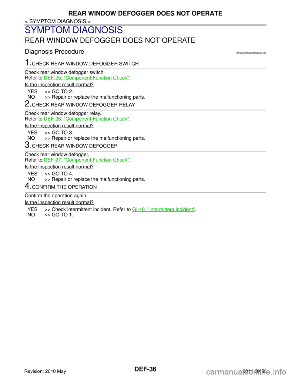
REAR WINDOW DEFOGGER DOES NOT OPERATE
SYMPTOM DIAGNOSIS
REAR WINDOW DEFOGGER DOES NOT OPERATE
Diagnosis ProcedureINFOID:0000000006299456
1.CHECK REAR WINDOW DEFOGGER SWITCH
Check rear window defogger switch.
Refer to DEF-25, "
Component Function Check".
Is the inspection result normal?
YES >> GO TO 2.
NO >> Repair or replace the malfunctioning parts.
2.CHECK REAR WINDOW DEFOGGER RELAY
Check rear window defogger relay.
Refer to DEF-26, "
Component Function Check".
Is the inspection result normal?
YES >> GO TO 3.
NO >> Repair or replace the malfunctioning parts.
3.CHECK REAR WINDOW DEFOGGER
Check rear window defogger.
Refer to DEF-27, "
Component Function Check".
Is the inspection result normal?
YES >> GO TO 4.
NO >> Repair or replace the malfunctioning parts.
4.CONFIRM THE OPERATION
Confirm the operation again.
Is the inspection result normal?
YES >> Check intermittent incident. Refer to GI-40, "Intermittent Incident".
NO >> GO TO 1.
Revision: 2010 May2011 QX56
Page 1529 of 5598

REAR WINDOW DEFOGGER AND DOOR MIRROR DEFOGGER DO NOT OPER-
ATE.
DEF-37
< SYMPTOM DIAGNOSIS >
C
D E
F
G H
I
J
K
M A
B
DEF
N
O P
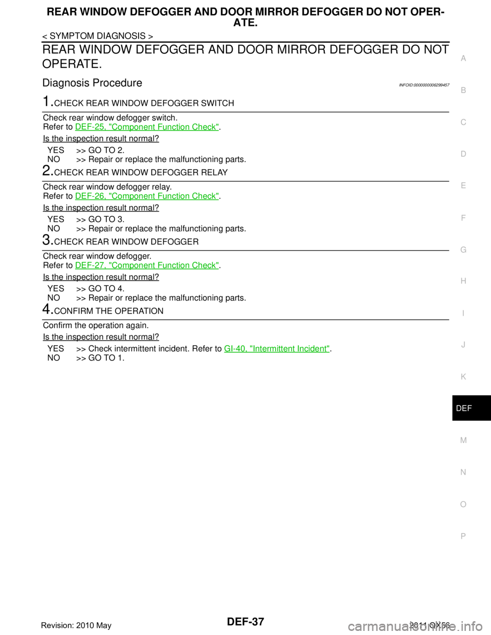
REAR WINDOW DEFOGGER AND DO OR MIRROR DEFOGGER DO NOT
OPERATE.
Diagnosis ProcedureINFOID:0000000006299457
1.CHECK REAR WINDOW DEFOGGER SWITCH
Check rear window defogger switch.
Refer to DEF-25, "
Component Function Check".
Is the inspection result normal?
YES >> GO TO 2.
NO >> Repair or replace the malfunctioning parts.
2.CHECK REAR WINDOW DEFOGGER RELAY
Check rear window defogger relay.
Refer to DEF-26, "
Component Function Check".
Is the inspection result normal?
YES >> GO TO 3.
NO >> Repair or replace the malfunctioning parts.
3.CHECK REAR WINDOW DEFOGGER
Check rear window defogger.
Refer to DEF-27, "
Component Function Check".
Is the inspection result normal?
YES >> GO TO 4.
NO >> Repair or replace the malfunctioning parts.
4.CONFIRM THE OPERATION
Confirm the operation again.
Is the inspection result normal?
YES >> Check intermittent incident. Refer to GI-40, "Intermittent Incident".
NO >> GO TO 1.
Revision: 2010 May2011 QX56
Page 1533 of 5598

WIPER DEICER DOSE NOT OPERATEDEF-41
< SYMPTOM DIAGNOSIS >
C
DE
F
G H
I
J
K
M A
B
DEF
N
O P
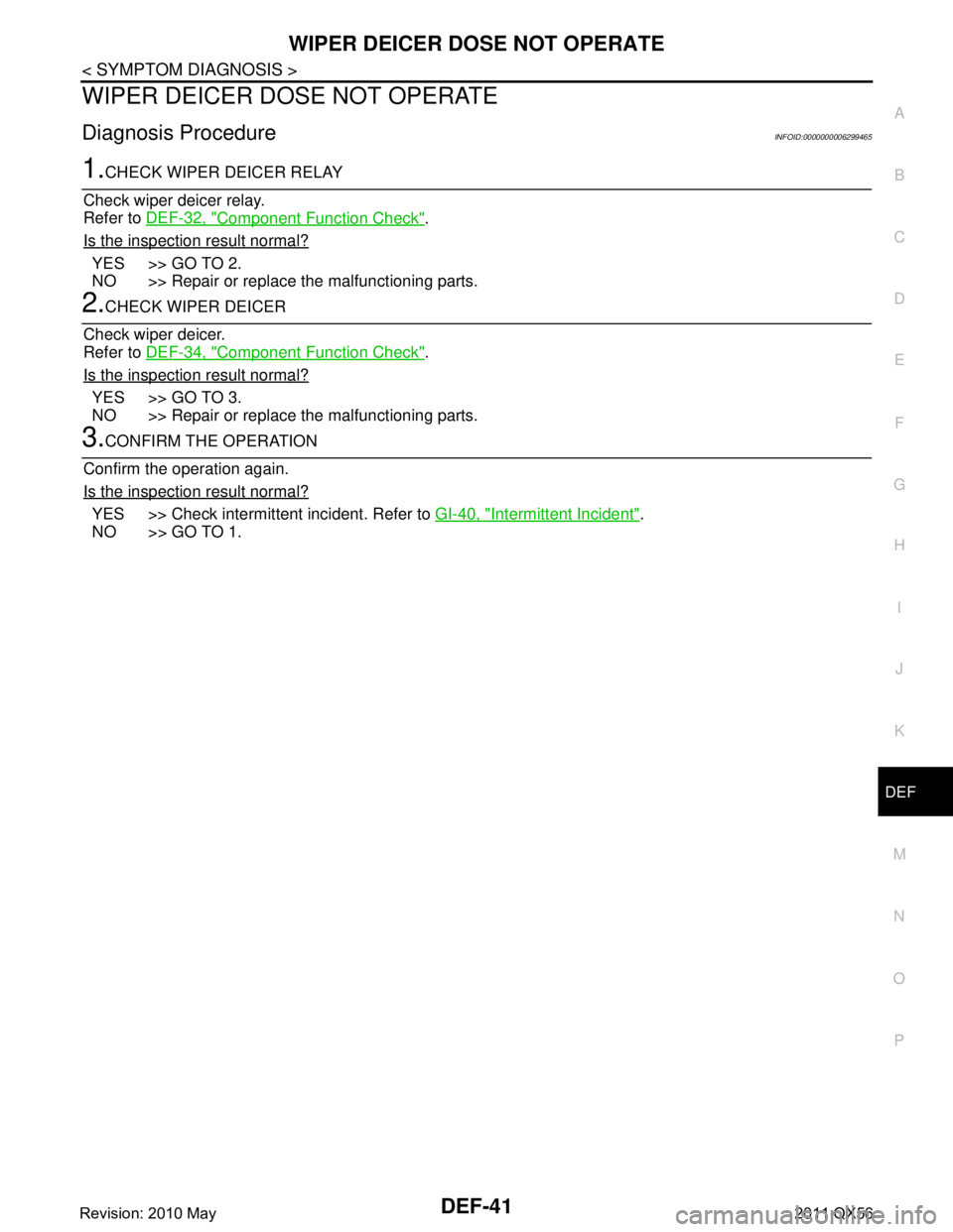
WIPER DEICER DOSE NOT OPERATE
Diagnosis ProcedureINFOID:0000000006299465
1.CHECK WIPER DEICER RELAY
Check wiper deicer relay.
Refer to DEF-32, "
Component Function Check".
Is the inspection result normal?
YES >> GO TO 2.
NO >> Repair or replace the malfunctioning parts.
2.CHECK WIPER DEICER
Check wiper deicer.
Refer to DEF-34, "
Component Function Check".
Is the inspection result normal?
YES >> GO TO 3.
NO >> Repair or replace the malfunctioning parts.
3.CONFIRM THE OPERATION
Confirm the operation again.
Is the inspection result normal?
YES >> Check intermittent incident. Refer to GI-40, "Intermittent Incident".
NO >> GO TO 1.
Revision: 2010 May2011 QX56
Page 1578 of 5598

DLK-42
< SYSTEM DESCRIPTION >
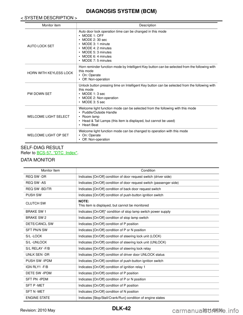
DIAGNOSIS SYSTEM (BCM)
SELF-DIAG RESULT
Refer to BCS-57, "DTCIndex".
DATA MONITOR
AUTO LOCK SET Auto door lock operation time can be changed in this mode
MODE 1: OFF
MODE 2: 30 sec
MODE 3: 1 minute
MODE 4: 2 minutes
MODE 5: 3 minutes
MODE 6: 4 minutes
MODE 7: 5 minutes
HORN WITH KEYLESS LOCK Horn reminder function mode by Intelligent Key button can be selected from the following with
this mode
On: Operate
Off: Non-operation
PW DOWN SET Unlock button pressing time on Intelligent Key button can be selected from the following with
this mode
MODE 1: 3 sec
MODE 2: Non-operation
MODE 3: 5 sec
WELCOME LIGHT SELECT Welcome light function mode can be selected from the following with this mode
Puddle/Outside Handle
Room lamp
Head & Tail Lamps (this item is displayed, but cannot be used)
Heart Beat
WELCOME LIGHT OP SET Welcome light function mode can be changed to operation with this mode
On: Operate
Off: Non-operation
Monitor item Description
Monitor Item Condition
REQ SW -DR Indicates [On/Off] condition of door request switch (driver side)
REQ SW -AS Indicates [On/Off] condition of door request switch (passenger side)
REQ SW -BD/TR Indicates [On/Off] condition of back door request switch
PUSH SW Indicates [On/Off] condition of push-button ignition switch
CLUTCH SW NOTE:
This item is displayed, but cannot be monitored
BRAKE SW 1 Indicates [On/Off]* condition of stop lamp switch power supply
BRAKE SW 2 Indicates [On/Off] condition of stop lamp switch
DETE/CANCL SW Indicates [On/Off] condition of P position
SFT PN/N SW Indicates [On/Off] condition of P or N position
S/L -LOCK Indicates [On/Off] condition of steering lock unit (LOCK)
S/L -UNLOCK Indicates [On/Off] condition of steering lock unit (UNLOCK)
S/L RELAY -F/B Indicates [On/Off] condition of steering lock relay
UNLK SEN -DR Indicates [On/Off] condition of driver door UNLOCK status
PUSH SW -IPDM Indicates [On/Off] condition of push-button ignition switch
IGN RLY1 -F/B Indicates [On/Off] condition of ignition relay 1
DETE SW -IPDM Indicates [On/Off] condition of P position
SFT PN -IPDM Indicates [On/Off] condition of P or N position
SFT P -MET Indicates [On/Off] condition of P position
SFT N -MET Indicates [On/Off] condition of N position
ENGINE STATE Indicates [Stop/Stall/Crank/Run] condition of engine states
Revision: 2010 May2011 QX56
Page 1579 of 5598

DIAGNOSIS SYSTEM (BCM)DLK-43
< SYSTEM DESCRIPTION >
C
DE
F
G H
I
J
L
M A
B
DLK
N
O P
*: OFF is displayed when brake pedal is depressed while brake switch power supply is OFF.
ACTIVE TEST
S/L LOCK-IPDM Indicates [On/Off] condition of steering lock unit (LOCK)
S/L UNLK-IPDM Indicates [On/Off] condition of steering lock unit (UNLOCK)
S/L RELAY-REQ Indicates [On/Off] condition of steering lock relay
VEH SPEED 1 Display the vehicle speed signal received from combination meter by numerical value [Km/h]
VEH SPEED 2 Display the vehicle spee d signal received from ABS or VDC or TCM by numerical value [Km/h]
DOOR STAT-DR Indicates [LOCK/READY/UNLK] condition of unlock sensor
DOOR STAT-AS Indicates [LOCK/READY/UNLK] condition of passenger side door status
ID OK FLAG Indicates [Set/Reset] condition of key ID
PRMT ENG STRT Indicates [Set/Reset] condition of engine start possibility
PRMT RKE STRT NOTE:
This item is displayed, but cannot be monitored
TRNK/HAT MNTR NOTE:
This item is displayed, but cannot be monitored
RKE-LOCK Indicates [On/Off] condition of LOCK signal from Intelligent Key
RKE-UNLOCK Indicates [On/Off] condition of UNLOCK signal from Intelligent Key
RKE-TR/BD NOTE:
This item is displayed, but cannot be monitored
RKE-PANIC Indicates [On/Off] condition of PANIC button of Intelligent Key
RKE-MODE CHG Indicates [On/Off] condition of MODE CHANGE signal from Intelligent Key
RKE OPE COUN1 When remote keyless entry receiver receives the signal transmitted while operating on Intelli-
gent Key, the numerical value start changing
RKE OPE COUN2 NOTE:
This item is displayed, but cannot be monitored
Monitor Item Condition
Test item Description
BATTERY SAVER This test is able to check interior room lamp operation
On: Operate
Off: Non-operation
OUTSIDE BUZZER This test is able to check Intelligent Key warning buzzer operation
On: Operate
Off: Non-operation
INSIDE BUZZER This test is able to check warning chime in combination meter operation
Take Out: Take away warning chime sounds when CONSULT-III screen is touched
Key: Key warning chime sounds when CONSULT-III screen is touched
Knob: OFF position warning chime sounds when CONSULT-III screen is touched
Off: Non-operation
INDICATOR This test is able to check warning lamp operation
KEY ON: “KEY” Warning lamp illuminates when CONSULT-III screen is touched
KEY IND: “KEY” Warning lamp blinks when CONSULT-III screen is touched
Off: Non-operation
INT LAMP This test is able to check interior room lamp operation
On: Operate
Off: Non-operation
Revision: 2010 May2011 QX56
Page 2025 of 5598

EC-1
ENGINE
C
DE
F
G H
I
J
K L
M
SECTION EC
A
EC
N
O P
CONTENTS
ENGINE CONTROL SYSTEM
VK56VD
PRECAUTION ................ ...............................
9
PRECAUTIONS .............................................. .....9
Precaution for Supplemental Restraint System
(SRS) "AIR BAG" and "SEAT BELT PRE-TEN-
SIONER" ............................................................. ......
9
Precaution for Procedure without Cowl Top Cover ......9
Precautions For Xenon Headlamp Service ...............9
On Board Diagnostic (OBD) System of Engine
and A/T ....................................................................
10
General Precautions ...............................................10
PREPARATION ...........................................14
PREPARATION .............................................. ....14
Special Service Tools .......................................... ....14
Commercial Service Tools ......................................14
SYSTEM DESCRIPTION .............................16
COMPONENT PARTS ................................... ....16
Component Parts Location .................................. ....16
Component Description ...........................................19
Accelerator Pedal Position Sensor ..........................21
Air Fuel Ratio (A/F) Sensor 1 ..................................21
ASCD Brake Switch & Stop Lamp Switch ...............21
ASCD Steering Switch ............................................21
ASCD Indicators ......................................................21
Battery Current Sensor (With Battery Tempera-
ture Sensor) ............................................................
22
Camshaft Position Sensor .......................................22
Crankshaft Position Sensor .....................................23
ECM ........................................................................23
Electric Throttle Control Actuator ............................23
Electrically-controlled cooling fan coupling .............24
Engine Coolant Temperature Sensor ......................25
Engine Oil Temperature Sensor ..............................25
EVAP Control System Pressure Sensor .................26
EVAP Canister Vent Control Valve .........................26
EVAP Canister Purge Volume Control Solenoid
Valve .................................................................... ....
26
Fuel Injector .............................................................26
Fuel Level Sensor ....................................................26
Fuel Pump Control Module ......................................27
Fuel Rail Pressure Sensor .......................................27
Fuel Tank Temperature Sensor ...............................27
Heated Oxygen Sensor 2 ........................................27
High Pressure Fuel Pump .......................................28
ICC Brake Switch & Stop Lamp Switch ...................29
ICC Steering Switch ................................................29
Ignition Coil With Power Transistor .........................29
Intake Valve Timing Control Solenoid Valve ...........29
Knock Sensor ...................................................... ....30
Low Fuel Pressure Sensor ......................................30
Low Pressure Fuel Pump ........................................30
Malfunction Indicator Lamp (MIL) ............................30
Manifold Absolute Pressure Sensor ........................31
Mass Air Flow Sensor (With Intake Air Tempera-
ture Sensor) .............................................................
31
Power Steering Pressure (PSP) Sensor ..................31
Refrigerant Pressure Sensor ............................... ....32
VVEL Actuator Motor ...............................................32
VVEL Actuator Motor Relay .....................................32
VVEL Control Module ..............................................32
VVEL Control Shaft Position Sensor .......................32
STRUCTURE AND OPERATION .....................33
Positive Crankcase Ventilation ................................33
On Board Refueling Vapor Recovery (ORVR) ........34
SYSTEM ............................................................35
ENGINE CONTROL SYSTEM ........................ ...........35
ENGINE CONTROL SYSTEM : System Diagram ....35
ENGINE CONTROL SYSTEM : System Descrip-
tion ...........................................................................
35
DIRECT INJECTION GASOLINE SYSTEM .......... ....36
DIRECT INJECTION GASOLINE SYSTEM :
System Diagram .....................................................
36
Revision: 2010 May2011 QX56
Page 2030 of 5598

EC-6
DTC Logic ..............................................................364
Diagnosis Procedure .............................................365
P0527 COOLING FAN SPEED SENSOR .......367
DTC Logic ............................................................ ..367
Diagnosis Procedure .............................................367
Component Inspection (Cooling Fan Speed Sen-
sor) ........................................................................
369
P0550 PSP SENSOR .......................................371
DTC Logic ............................................................ ..371
Diagnosis Procedure .............................................371
Component Inspection (Power Steering Pressure
Sensor) ..................................................................
373
P0603 ECM POWER SUPPLY ........................374
DTC Logic ............................................................ ..374
Diagnosis Procedure .............................................374
P0605 ECM ......................................................376
DTC Logic ............................................................ ..376
Diagnosis Procedure .............................................376
P0607 ECM ......................................................378
DTC Logic ............................................................ ..378
Diagnosis Procedure .............................................378
P0611 ECM PROTECTION .............................379
Description ........................................................... ..379
DTC Logic ..............................................................379
Diagnosis Procedure .............................................379
P062B ECM .....................................................380
Description ........................................................... ..380
DTC Logic ..............................................................380
Diagnosis Procedure .............................................380
P0643 SENSOR POWER SUPPLY .................381
DTC Logic ............................................................ ..381
Diagnosis Procedure .............................................381
P0850 PNP SWITCH .......................................383
Description ........................................................... ..383
DTC Logic ..............................................................383
Component Function Check ..................................384
Diagnosis Procedure .............................................384
P1087, P1088 VVEL SYSTEM ........................386
DTC Logic ............................................................ ..386
Diagnosis Procedure .............................................386
P1089, P1092 VVEL CONTROL SHAFT PO-
SITION SENSOR .............................................
387
DTC Logic ............................................................ ..387
Diagnosis Procedure .............................................387
P1090, P1093 VVEL ACTUATOR MOTOR .....390
DTC Logic ............................................................ ..390
Diagnosis Procedure .............................................390
Component Inspection (VVEL ACTUATOR MO-
TOR ASSEMBLY) .................................................
392
Component Inspection (VVEL ACTUATOR
HOUSING ASSEMBLY) ......... ...............................
392
P1091 VVEL ACTUATOR MOTOR RELAY ... ..393
DTC Logic ............................................................ .393
Diagnosis Procedure .............................................393
Component Inspection (VVEL Actuator Motor Re-
lay) ....................................................................... .
395
P1148, P1168 CLOSED LOOP CONTROL .....396
DTC Logic ............................................................ .396
Diagnosis Procedure .............................................396
P1197 OUT OF GAS ........................................397
Description ........................................................... .397
DTC Logic .............................................................397
Diagnosis Procedure .............................................398
P1212 TCS COMMUNICATION LINE ..............399
Description ........................................................... .399
DTC Logic .............................................................399
Diagnosis Procedure .............................................399
P1217 ENGINE OVER TEMPERATURE .........400
DTC Logic ............................................................ .400
Component Function Check .................................400
Diagnosis Procedure .............................................401
P1220 FUEL PUMP CONTROL MODULE
(FPCM) ..............................................................
403
DTC Logic ............................................................ .403
Diagnosis Procedure .............................................403
Component Inspection (FPCM) ............................405
P1225 TP SENSOR ..........................................406
DTC Logic ............................................................ .406
Diagnosis Procedure .............................................406
P1226 TP SENSOR ..........................................407
DTC Logic ............................................................ .407
Diagnosis Procedure .............................................407
P1421 COLD START CONTROL .....................408
Description ........................................................... .408
DTC Logic .............................................................408
Diagnosis Procedure .............................................408
P1423, P1424 COLD START CONTROL ........410
Description ........................................................... .410
DTC Logic .............................................................410
Diagnosis Procedure .............................................410
P1550 BATTERY CURRENT SENSOR ...........412
DTC Logic ............................................................ .412
Diagnosis Procedure .............................................412
Component Inspection (Battery Current Sensor) ..414
P1551, P1552 BATTERY CURRENT SEN-
SOR ..................................................................
416
DTC Logic ............................................................ .416
Diagnosis Procedure .............................................416
Component Inspection (Battery Current Sensor) ..419
Revision: 2010 May2011 QX56
Page 2031 of 5598

EC-7
C
DE
F
G H
I
J
K L
M
EC A
N
O P
P1553 BATTERY CURRENT SENSOR ......... ..420
DTC Logic ........................................................... ..420
Diagnosis Procedure .............................................420
Component Inspection (Battery Current Sensor) ..423
P1554 BATTERY CURRENT SENSOR ...........424
DTC Logic ........................................................... ..424
Component Function Check ..................................424
Diagnosis Procedure .............................................425
Component Inspection (Battery Current Sensor) ..427
P1556, P1557 BATTERY TEMPERATURE
SENSOR ...........................................................
428
DTC Logic ........................................................... ..428
Diagnosis Procedure .............................................428
Component Inspection (Battery Temprature Sen-
sor) ........................................................................
430
P1564 ASCD STEERING SWITCH ..................431
DTC Logic ........................................................... ..431
Diagnosis Procedure .............................................431
Component Inspection (ASCD Steering Switch) ...433
P1564 ICC STEERING SWITCH ......................434
DTC Logic ........................................................... ..434
Diagnosis Procedure .............................................434
Component Inspection (ICC Steering Switch) .......436
P1568 ICC FUNCTION .....................................437
DTC Logic ........................................................... ..437
Diagnosis Procedure .............................................437
P1572 ASCD BRAKE SWITCH .......................438
DTC Logic ........................................................... ..438
Diagnosis Procedure .............................................439
Component Inspection (ASCD Brake Switch) .......442
Component Inspection (Stop Lamp Switch) ..........442
P1572 ICC BRAKE SWITCH ...........................443
DTC Logic ........................................................... ..443
Diagnosis Procedure .............................................444
Component Inspection (ICC Brake Switch) ...........445
Component Inspection (Stop Lamp Switch) ..........446
P1574 ASCD VEHICLE SPEED SENSOR ......447
Description .......................................................... ..447
DTC Logic .............................................................447
Diagnosis Procedure .............................................447
P1574 ICC VEHICLE SPEED SENSOR ..........449
Description .......................................................... ..449
DTC Logic .............................................................449
Diagnosis Procedure .............................................449
P1606 VVEL CONTROL MODULE ..................451
DTC Logic ........................................................... ..451
Diagnosis Procedure .............................................451
P1607 VVEL CONTROL MODULE ..................452
DTC Logic ........................................................... ..452
Diagnosis Procedure .............................................452
P1608 VVEL SENSOR POWER SUPPLY ......453
DTC Logic ............................................................ ..453
Diagnosis Procedure .............................................453
P1805 BRAKE SWITCH .................................455
DTC Logic ..............................................................455
Diagnosis Procedure .............................................455
Component Inspection (Stop Lamp Switch) ..........456
P2100, P2103 THROTTLE CONTROL MO-
TOR RELAY ....................................................
458
DTC Logic ..............................................................458
Diagnosis Procedure .............................................458
P2101 ELECTRIC THROTTLE CONTROL
FUNCTION ......................................................
460
Description ........................................................... ..460
DTC Logic ..............................................................460
Diagnosis Procedure .............................................460
Component Inspection ...........................................462
Special Repair Requirement ..................................463
P2118 THROTTLE CONTROL MOTOR .........464
DTC Logic ..............................................................464
Diagnosis Procedure .............................................464
Component Inspection (Electric Throttle Control
Motor) ....................................................................
465
P2119 ELECTRIC THROTTLE CONTROL
ACTUATOR .....................................................
466
DTC Logic ..............................................................466
Diagnosis Procedure .............................................466
P2122, P2123 APP SENSOR .........................468
DTC Logic ..............................................................468
Diagnosis Procedure .............................................468
Component Inspection (Accelerator Pedal Posi-
tion Sensor) ...........................................................
470
P2127, P2128 APP SENSOR .........................471
DTC Logic ..............................................................471
Diagnosis Procedure .............................................471
Component Inspection (Accelerator Pedal Posi-
tion Sensor) ...........................................................
474
P2135 TP SENSOR .........................................475
DTC Logic ..............................................................475
Diagnosis Procedure .............................................475
Component Inspection (Throttle Position Sensor) ..476
P2138 APP SENSOR ......................................478
DTC Logic ..............................................................478
Diagnosis Procedure .............................................478
Component Inspection (Accelerator Pedal Posi-
tion Sensor) ...........................................................
481
P2539, P2541, P2542 LOW FUEL PRES-
SURE SENSOR ...............................................
483
DTC Logic ..............................................................483
Diagnosis Procedure .............................................483
Component Inspection ...........................................485
Revision: 2010 May2011 QX56