Page 1648 of 5598
DLK-112
< DTC/CIRCUIT DIAGNOSIS >
B2627 OUTSIDE ANTENNA
B2627 OUTSIDE ANTENNA
DTC LogicINFOID:0000000006225916
DTC DETECTION LOGIC
DTC CONFIRMATION PROCEDURE
1.PERFORM DTC CONFIRMATION PROCEDURE
1. Turn ignition switch ON.
2. Check “Self Diagnostic Result” m ode of “BCM” using CONSULT-III.
Is DTC detected?
YES >> Refer to DLK-108, "Diagnosis Procedure".
NO >> Outside key antenna (passenger side) is OK.
Diagnosis ProcedureINFOID:0000000006225917
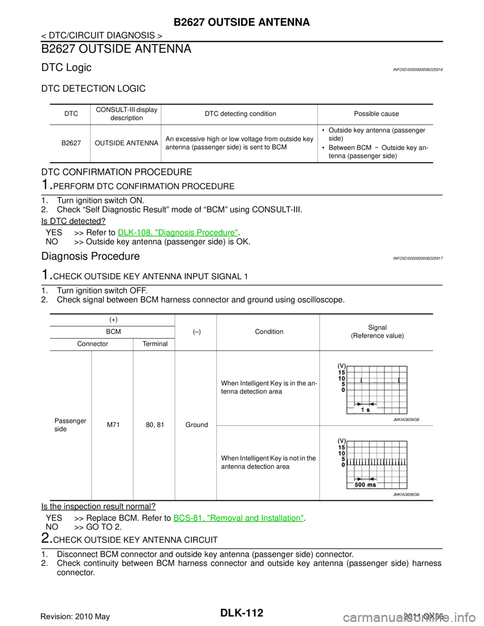
1.CHECK OUTSIDE KEY ANTENNA INPUT SIGNAL 1
1. Turn ignition switch OFF.
2. Check signal between BCM harness connector and ground using oscilloscope.
Is the inspection result normal?
YES >> Replace BCM. Refer to BCS-81, "Removal and Installation".
NO >> GO TO 2.
2.CHECK OUTSIDE KEY ANTENNA CIRCUIT
1. Disconnect BCM connector and outside key antenna (passenger side) connector.
2. Check continuity between BCM harness connector and outside key antenna (passenger side) harness connector.
DTC CONSULT-III display
description DTC detecting condition Possible cause
B2627 OUTSIDE ANTENNA An excessive high or low voltage from outside key
antenna (passenger side) is sent to BCM Outside key antenna (passenger
side)
Between BCM �™Outside key an-
tenna (passenger side)
(+)
(–) Condition Signal
(Reference value)
BCM
Connector Terminal
Passenger
side M71 80, 81 Ground When Intelligent Key is in the an-
tenna detection area
When Intelligent Key is not in the
antenna detection area
JMKIA3839GB
JMKIA3838GB
Revision: 2010 May2011 QX56
Page 1649 of 5598
B2627 OUTSIDE ANTENNADLK-113
< DTC/CIRCUIT DIAGNOSIS >
C
DE
F
G H
I
J
L
M A
B
DLK
N
O P
3. Check continuity between BCM harness connector and ground.
Is the inspection result normal?
YES >> GO TO 3.
NO >> Repair or replace harness.
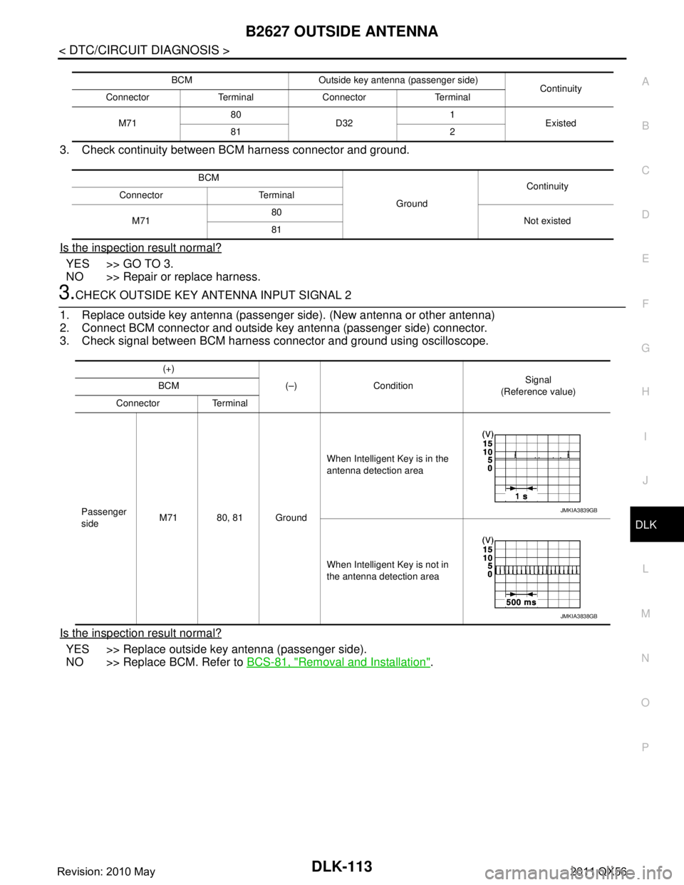
3.CHECK OUTSIDE KEY ANTENNA INPUT SIGNAL 2
1. Replace outside key antenna (passenger side). (New antenna or other antenna)
2. Connect BCM connector and outside key antenna (passenger side) connector.
3. Check signal between BCM harness connector and ground using oscilloscope.
Is the inspection result normal?
YES >> Replace outside key antenna (passenger side).
NO >> Replace BCM. Refer to BCS-81, "
Removal and Installation".
BCM Outside key antenna (passenger side)
Continuity
Connector Terminal Connector Terminal
M71 80
D32 1
Existed
81 2
BCM GroundContinuity
Connector Terminal
M71 80
Not existed
81
(+)
(–) Condition Signal
(Reference value)
BCM
Connector Terminal
Passenger
side M71 80, 81 Ground When Intelligent Key is in the
antenna detection area
When Intelligent Key is not in
the antenna detection area
JMKIA3839GB
JMKIA3838GB
Revision: 2010 May2011 QX56
Page 1650 of 5598
DLK-114
< DTC/CIRCUIT DIAGNOSIS >
B2628 OUTSIDE ANTENNA
B2628 OUTSIDE ANTENNA
DTC LogicINFOID:0000000006225918
DTC DETECTION LOGIC
DTC CONFIRMATION PROCEDURE
1.PERFORM DTC CONFIRMATION PROCEDURE
1. Turn ignition switch ON.
2. Check “Self Diagnostic Result” m ode of “BCM” using CONSULT-III.
Is DTC detected?
YES >> Refer to DLK-108, "Diagnosis Procedure".
NO >> Outside key antenna (back door) is OK.
Diagnosis ProcedureINFOID:0000000006225919
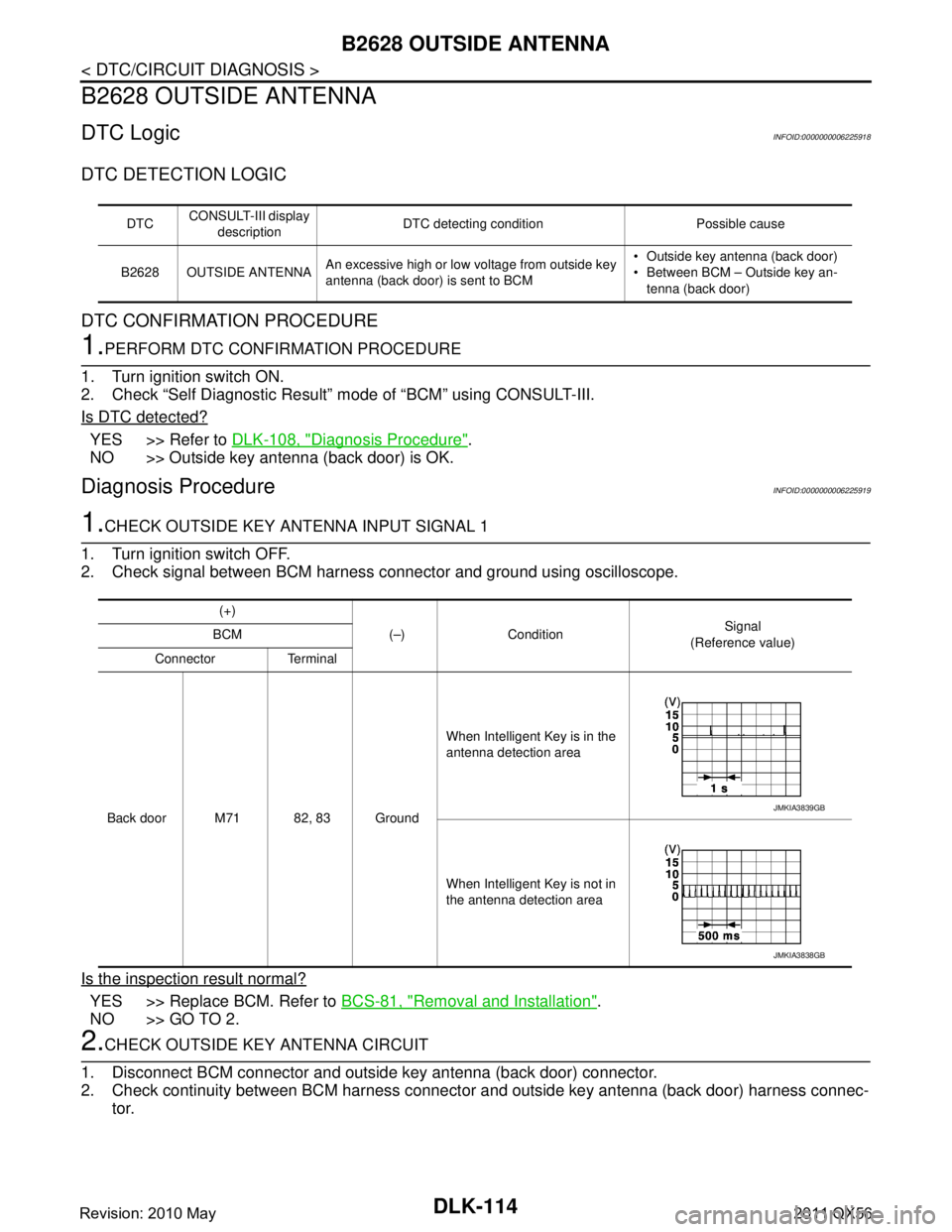
1.CHECK OUTSIDE KEY ANTENNA INPUT SIGNAL 1
1. Turn ignition switch OFF.
2. Check signal between BCM harness connector and ground using oscilloscope.
Is the inspection result normal?
YES >> Replace BCM. Refer to BCS-81, "Removal and Installation".
NO >> GO TO 2.
2.CHECK OUTSIDE KEY ANTENNA CIRCUIT
1. Disconnect BCM connector and outside key antenna (back door) connector.
2. Check continuity between BCM harness connector and outside key antenna (back door) harness connec- tor.
DTC CONSULT-III display
description DTC detecting condition Possible cause
B2628 OUTSIDE ANTENNA An excessive high or low voltage from outside key
antenna (back door) is sent to BCM Outside key antenna (back door)
Between BCM – Outside key an-
tenna (back door)
(+)
(–) Condition Signal
(Reference value)
BCM
Connector Terminal
Back door M71 82, 83 Ground When Intelligent Key is in the
antenna detection area
When Intelligent Key is not in
the antenna detection area
JMKIA3839GB
JMKIA3838GB
Revision: 2010 May2011 QX56
Page 1651 of 5598
B2628 OUTSIDE ANTENNADLK-115
< DTC/CIRCUIT DIAGNOSIS >
C
DE
F
G H
I
J
L
M A
B
DLK
N
O P
3. Check continuity between BCM harness connector and ground.
Is the inspection result normal?
YES >> GO TO 3.
NO >> Repair or replace harness.
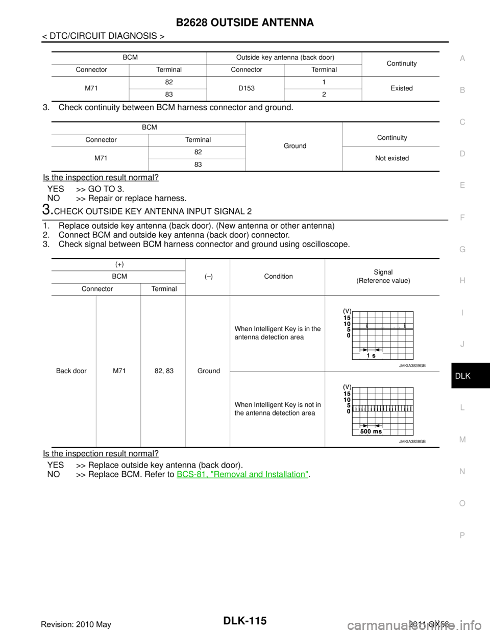
3.CHECK OUTSIDE KEY ANTENNA INPUT SIGNAL 2
1. Replace outside key antenna (back door). (New antenna or other antenna)
2. Connect BCM and outside key antenna (back door) connector.
3. Check signal between BCM harness connector and ground using oscilloscope.
Is the inspection result normal?
YES >> Replace outside key antenna (back door).
NO >> Replace BCM. Refer to BCS-81, "
Removal and Installation".
BCM Outside key antenna (back door)
Continuity
Connector Terminal Connector Terminal
M71 82
D153 1
Existed
83 2
BCM GroundContinuity
Connector Terminal
M71 82
Not existed
83
(+)
(–) Condition Signal
(Reference value)
BCM
Connector Terminal
Back door M71 82, 83 Ground When Intelligent Key is in the
antenna detection area
When Intelligent Key is not in
the antenna detection area
JMKIA3839GB
JMKIA3838GB
Revision: 2010 May2011 QX56
Page 1666 of 5598
DLK-130
< DTC/CIRCUIT DIAGNOSIS >
UNLOCK SENSOR
UNLOCK SENSOR
Component Function CheckINFOID:0000000006225941
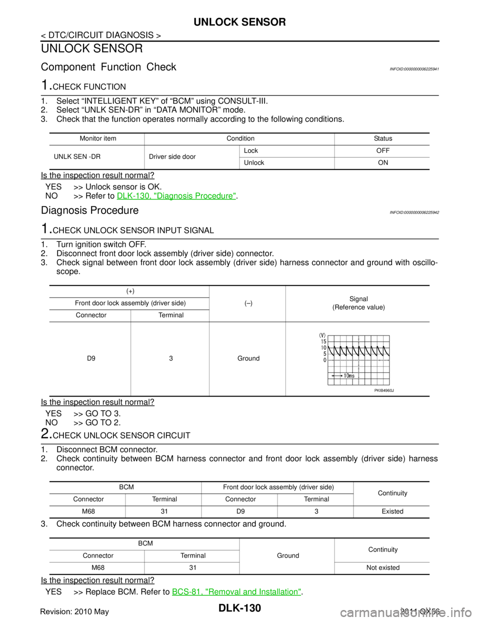
1.CHECK FUNCTION
1. Select “INTELLIGE NT KEY” of “BCM” using CONSULT-III.
2. Select “UNLK SEN-DR” in “DATA MONITOR” mode.
3. Check that the function operates normall y according to the following conditions.
Is the inspection result normal?
YES >> Unlock sensor is OK.
NO >> Refer to DLK-130, "
Diagnosis Procedure".
Diagnosis ProcedureINFOID:0000000006225942
1.CHECK UNLOCK SENSOR INPUT SIGNAL
1. Turn ignition switch OFF.
2. Disconnect front door lock assembly (driver side) connector.
3. Check signal between front door lock assembly (d river side) harness connector and ground with oscillo-
scope.
Is the inspection result normal?
YES >> GO TO 3.
NO >> GO TO 2.
2.CHECK UNLOCK SENSOR CIRCUIT
1. Disconnect BCM connector.
2. Check continuity between BCM harness connector and front door lock assembly (driver side) harness connector.
3. Check continuity between BCM harness connector and ground.
Is the inspection result normal?
YES >> Replace BCM. Refer to BCS-81, "Removal and Installation".
Monitor item Condition Status
UNLK SEN -DR Driver side door Lock OFF
Unlock ON
(+)
(–)Signal
(Reference value)
Front door lock assembly (driver side)
Connector Terminal
D9 3 Ground
PKIB4960J
BCM Front door lock assembly (driver side) Continuity
Connector Terminal Connector Terminal
M68 31 D9 3 Existed
BCM GroundContinuity
Connector Terminal
M68 31 Not existed
Revision: 2010 May2011 QX56
Page 1668 of 5598

DLK-132
< DTC/CIRCUIT DIAGNOSIS >
DOOR KEY CYLINDER SWITCH
DOOR KEY CYLINDER SWITCH
Component Function CheckINFOID:0000000006225944
1.CHECK FUNCTION
1. Select “DOOR LOCK” of “BCM” using CONSULT-III.
2. Select “KEY CYL LK-SW”, “KEY CY L UN-SW” in “DATA MONITOR” mode.
3. Check that the function operates normall y according to the following conditions.
Is the inspection result normal?
YES >> Door key cylinder switch is OK.
NO >> Refer to DLK-132, "
Diagnosis Procedure".
Diagnosis ProcedureINFOID:0000000006225945
1.CHECK DOOR KEY CYLINDER SWITCH INPUT SIGNAL
1. Turn ignition switch OFF.
2. Disconnect front door lock assembly (driver side) connector.
3. Check voltage between front door lock assembly (driver side) harness connector and ground.
Is the inspection result normal?
YES >> GO TO 3.
NO >> GO TO 2.
2.CHECK DOOR KEY CYLINDER SWITCH SIGNAL CIRCUIT
1. Disconnect power window main switch connector.
2. Check continuity between power window main s witch harness connector and front door lock assembly
(driver side) harness connector.
3. Check continuity between power window main switch harness connector and ground.
Is the inspection result normal?
YES >> Replace power window main switch. Refer to PWC-74, "Removal and Installation".
Monitor item Condition Status
KEY CYL LK-SW Driver side door key cylinder Lock ON
Neutral / Unlock OFF
KEY CYL UN-SW Unlock ON
Neutral / Lock OFF
(+)
(–)Vo l ta g e
(Approx.)
Front door lock assembly (driver side)
Connector Terminal
D9 5
Ground 5 V
6
Power window main switch Front do or lock assembly (driver side)
Continuity
Connector Terminal Connector Terminal
D5 4
D9 6
Existed
65
Power window main switch GroundContinuity
Connector Terminal
D5 4
Not existed
6
Revision: 2010 May2011 QX56
Page 1669 of 5598

DOOR KEY CYLINDER SWITCHDLK-133
< DTC/CIRCUIT DIAGNOSIS >
C
DE
F
G H
I
J
L
M A
B
DLK
N
O P
NO >> Repair or replace harness.
3.CHECK DOOR KEY CYLINDER SWITCH GROUND CIRCUIT
Check continuity between front door lock assembly (driver side) harness connector and ground.
Is the inspection result normal?
YES >> GO TO 4.
NO >> Repair or replace harness.
4.CHECK DOOR KEY CYLINDER SWITCH
Refer to DLK-133, "
Component Inspection".
Is the inspection result normal?
YES >> GO TO 5.
NO >> Replace front door lock assembly (driver side).
5.CHECK INTERMITTENT INCIDENT
Refer to GI-40, "
Intermittent Incident".
>> INSPECTION END
Component InspectionINFOID:0000000006225946
1.CHECK DOOR KEY CYLINDER SWITCH
1. Turn ignition switch OFF.
2. Disconnect front door lock assembly (driver side) connector.
3. Check continuity between front door lock assembly (driver side) terminals.
Is the inspection result normal?
YES >> INSPECTION END
NO >> Replace front door lock assembly (driver side).
Front door lock assembly (driver side)
GroundContinuity
Connector Terminal
D9 4 Existed
Front door lock assembly (driver side) Condition Continuity
Te r m i n a l
5 4 Driver side door key cylinder Unlock Existed
Neutral / Lock Not existed
6 Lock Existed
Neutral / Unlock Not existed
Revision: 2010 May2011 QX56
Page 1670 of 5598
DLK-134
< DTC/CIRCUIT DIAGNOSIS >
REMOTE KEYLESS ENTRY RECEIVER
REMOTE KEYLESS ENTRY RECEIVER
Component Function CheckINFOID:0000000006225947
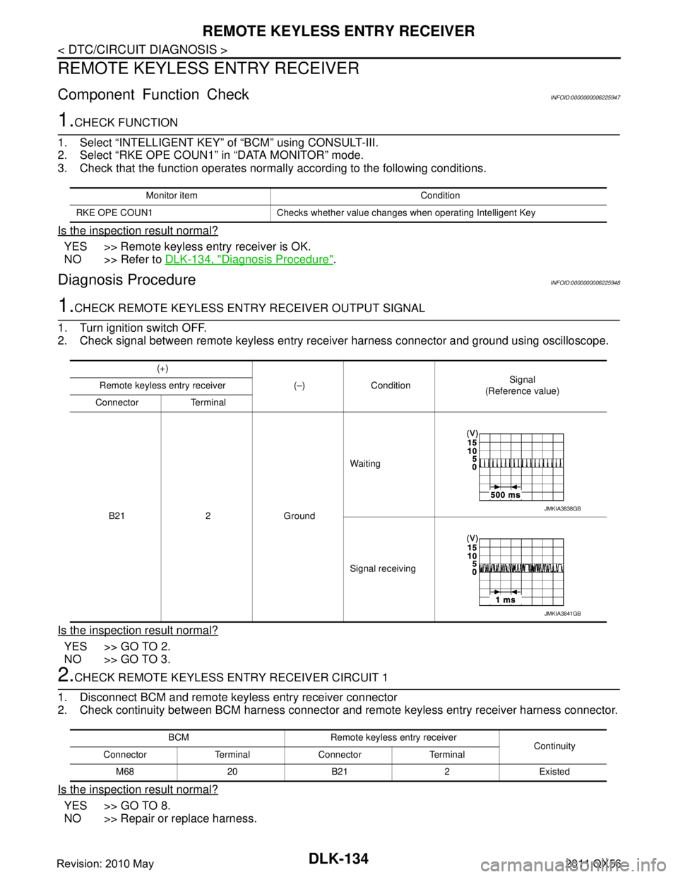
1.CHECK FUNCTION
1. Select “INTELLIGE NT KEY” of “BCM” using CONSULT-III.
2. Select “RKE OPE COUN1” in “DATA MONITOR” mode.
3. Check that the function operates normall y according to the following conditions.
Is the inspection result normal?
YES >> Remote keyless entry receiver is OK.
NO >> Refer to DLK-134, "
Diagnosis Procedure".
Diagnosis ProcedureINFOID:0000000006225948
1.CHECK REMOTE KEYLESS ENTRY RECEIVER OUTPUT SIGNAL
1. Turn ignition switch OFF.
2. Check signal between remote keyless entry receiver harness connector and ground using oscilloscope.
Is the inspection result normal?
YES >> GO TO 2.
NO >> GO TO 3.
2.CHECK REMOTE K EYLESS ENTRY RECEIVER CIRCUIT 1
1. Disconnect BCM and remote keyless entry receiver connector
2. Check continuity between BCM harness connector and remote keyless entry receiver harness connector.
Is the inspection result normal?
YES >> GO TO 8.
NO >> Repair or replace harness.
Monitor item Condition
RKE OPE COUN1 Checks whether value changes when operating Intelligent Key
(+) (–) Condition Signal
(Reference value)
Remote keyless entry receiver
Connector Terminal
B21 2 Ground Waiting
Signal receiving
JMKIA3838GB
JMKIA3841GB
BCM Remote keyless entry receiver
Continuity
Connector Terminal Connector Terminal
M68 20 B21 2 Existed
Revision: 2010 May2011 QX56