2011 INFINITI QX56 Eco
[x] Cancel search: EcoPage 5423 of 5598
WCS
DIAGNOSIS SYSTEM (BCM)WCS-19
< SYSTEM DESCRIPTION >
C
DE
F
G H
I
J
K L
M B A
O P
DIAGNOSIS SYSTEM (BCM)
COMMON ITEM
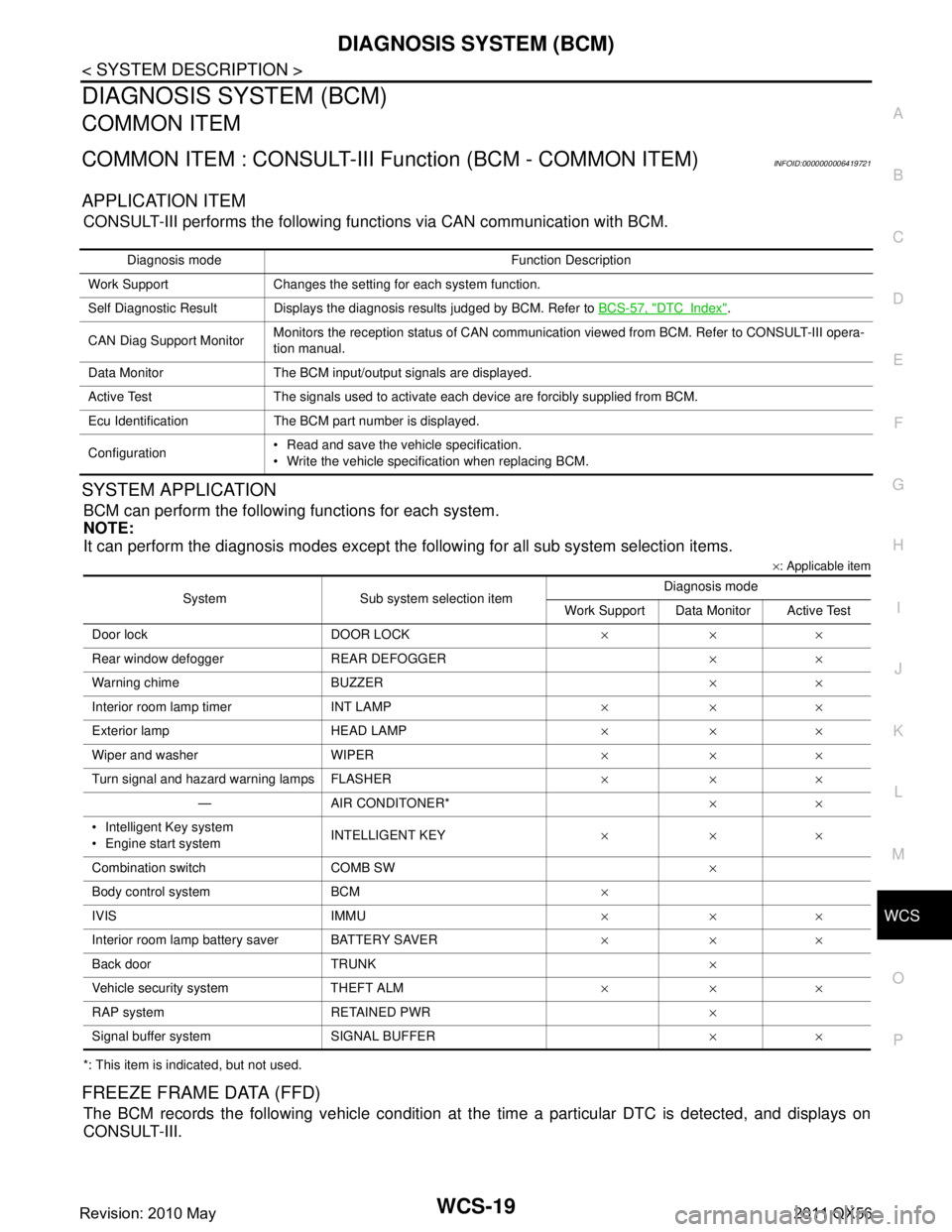
COMMON ITEM : CONSULT-III Fu nction (BCM - COMMON ITEM)INFOID:0000000006419721
APPLICATION ITEM
CONSULT-III performs the following functions via CAN communication with BCM.
SYSTEM APPLICATION
BCM can perform the following functions for each system.
NOTE:
It can perform the diagnosis modes except the following for all sub system selection items.
×: Applicable item
*: This item is indicated, but not used.
FREEZE FRAME DATA (FFD)
The BCM records the following vehicle condition at the time a particular DTC is detected, and displays on
CONSULT-III.
Diagnosis mode Function Description
Work Support Changes the setting for each system function.
Self Diagnostic Result Displays the diagnosis results judged by BCM. Refer to BCS-57, "
DTCIndex".
CAN Diag Support Monitor Monitors the reception status of CAN communication viewed from BCM. Refer to CONSULT-III opera-
tion manual.
Data Monitor The BCM input/output signals are displayed.
Active Test The signals used to activate each device are forcibly supplied from BCM.
Ecu Identification The BCM part number is displayed.
Configuration Read and save the vehicle specification.
Write the vehicle specification when replacing BCM.
System Sub system selection item Diagnosis mode
Work Support Data Monitor Active Test
Door lock DOOR LOCK ×××
Rear window defo gger REAR DEFOGGER ××
Warning chime BUZZER ××
Interior room lamp timer INT LAMP ×××
Exterior lamp HEAD LAMP ×××
Wiper and washer WIPER ×××
Turn signal and hazard warning lamps FLASHER ×××
— AIR CONDITONER* ××
Intelligent Key system
Engine start system INTELLIGENT KEY
×××
Combination switch COMB SW ×
Body control system BCM ×
IVIS IMMU ×××
Interior room lamp battery saver BATTERY SAVER ×××
Back door TRUNK ×
Vehicle security system THEFT ALM ×××
RAP system RETAINED PWR ×
Signal buffer system SIGNAL BUFFER ××
Revision: 2010 May2011 QX56
Page 5431 of 5598
WCS
COMBINATION METERWCS-27
< ECU DIAGNOSIS INFORMATION >
C
DE
F
G H
I
J
K L
M B A
O P
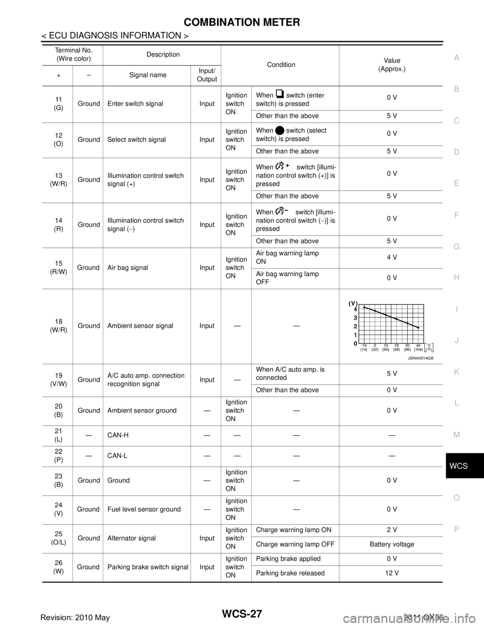
11
(G) Ground Enter switch signal Input Ignition
switch
ONWhen switch (enter
switch) is pressed
0 V
Other than the above 5 V
12
(O) Ground Select switch signal Input Ignition
switch
ONWhen switch (select
switch) is pressed
0 V
Other than the above 5 V
13
(W/R) Ground
Illumination control switch
signal (+) InputIgnition
switch
ON When switch [illumi-
nation control switch (+)] is
pressed
0 V
Other than the above 5 V
14
(R) Ground Illumination control switch
signal (
−) InputIgnition
switch
ON When switch [illumi-
nation control switch (
−)] is
pressed 0 V
Other than the above 5 V
15
(R/W) Ground Air bag signal Input Ignition
switch
ONAir bag warning lamp
ON
4 V
Air bag warning lamp
OFF 0 V
18
(W/R) Ground Ambient sensor signal Input — —
19
(V/W) Ground A/C auto amp. connection
recognition signal Input —When A/C auto amp. is
connected
5 V
Other than the above 0 V
20
(B) Ground Ambient sensor ground — Ignition
switch
ON—0 V
21
(L) —CAN-H — — — —
22
(P) —CAN-L — — — —
23
(B) Ground Ground — Ignition
switch
ON
—0 V
24
(V) Ground Fuel level sensor ground — Ignition
switch
ON—0 V
25
(O/L) Ground Alternator signal Input Ignition
switch
ONCharge warning lamp ON 2 V
Charge warning lamp OFF Battery voltage
26
(W) Ground Parking brake switch signal Input Ignition
switch
ONParking brake applied 0 V
Parking brake released 12 V
Te r m i n a l N o .
(Wire color) Description
ConditionVa l u e
(Approx.)
+ – Signal name Input/
Output
JSNIA0014GB
Revision: 2010 May2011 QX56
Page 5434 of 5598

WCS-30
< ECU DIAGNOSIS INFORMATION >
COMBINATION METER
DTC Index
INFOID:0000000006222690
Warning lamp/indicator lamp ABS warning lamp
The lamp turns ON by suspending communication.
VDC warning lamp
Brake warning lamp
IBA OFF indicator lamp
4WD warning lamp
Malfunction indicator lamp
VDC OFF indicator lamp
CRUISE warning lamp
Low tire pressure warning lamp The lamp blinking caused by suspending communication.
High beam indicator lamp
The lamp turns OFF by suspending communication.
Turn signal indicator lamp
Tail lamp indicator lamp
A/T CHECK indicator lamp
Key warning lamp
ATP warning lamp
Lane departure warning lamp
LDP ON indicator lamp
CRUISE indicator lamp
Oil pressure warning lamp
SNOW mode indicator lamp
TOW mode indicator lamp
CK SUSP indicator lamp
BSW indicator lamp
Function Specifications
Display contents of CONSULT-III Diagnostic item is detected when... Refer to
CAN COMM CIRCUIT
[U1000] When combination meter is not transmitting or receiving CAN communication signal
for 2 seconds or more. MWI-59,
"Diagnosis
Procedure"
CONTROL UNIT (CAN)
[U1010]
When detecting error during the initial diagnosis of the CAN controller of combina-
tion meter. MWI-60, "Diagnosis
Procedure"
VEHICLE SPEED
[B2205]
The abnormal vehicle sp
eed signal is input from the ABS actuator and electric unit
(control unit) for 2 seconds or more. MWI-61, "Diagnosis
Procedure"
ENGINE SPEED
[B2267]
If ECM continuously transmits abnormal engine speed signals for 2 seconds or
more. MWI-62, "Diagnosis
Procedure"
WATER TEMP
[B2268]
If ECM continuously transmits abnormal engine coolant temperature signals for 60
seconds or more. MWI-63, "Diagnosis
Procedure"
Revision: 2010 May2011 QX56
Page 5454 of 5598

WT-4
< PRECAUTION >
PRECAUTIONS
5. When the repair work is completed, re-connect both battery cables. With the brake pedal released, turn
the push-button ignition switch from ACC position to ON position, then to LOCK position. (The steering
wheel will lock when the push-button igniti on switch is turned to LOCK position.)
6. Perform self-diagnosis check of all control units using CONSULT-III.
Service Notice or Precautions for TPMSINFOID:0000000006225485
Low tire pressure warning lamp blinks for 1min, then turns ON when occurring any malfunction except low tire pressure. Erase the self-diagnosis memories for low tire pressure warning control unit, or register the ID
to turn low tire pressure warning lamp OFF. For ID registration, refer to WT-29, "
Work Procedure".
ID registration is required when replacing or rotating wheel s, replacing transmitter or low tire pressure warn-
ing control unit. Refer to WT-29, "
Work Procedure".
Replace grommet seal, valve core and cap of transmitter in TPMS, when replacing each tire by reaching the
wear limit. Refer to WT-66, "
Exploded View".
For tire inflation indicator function, refer to the following.
- When inflating the tires, park the vehicle in the safe area and ensure the safety of the working area.
- Read and understand the tire inflation indicator function prior to use.
- Inflate the tires one at a time.
- If there is no response for approximately 15 seconds or mo re after inflating the tires, cancel the use of the
tire inflation indicator function or move the vehicle approximately 1 m (3.2 ft) backward or forward to try
again. The air filler pressure may be weak or out of service area.
- Despite the high-precision TPMS pressure sensor, an i ndicated value may differ from that of the pressure
gauge.
- Air pressure is measured rather high due to the rise in tire air temperature after driving.
- If TPMS is malfunctioning, the tire inflation indicator is unusable.
Service Notice or Precautions for Road WheelINFOID:0000000006225486
Genuine NISSAN aluminum wheel is designed for each type of vehicle. Use it on the specified vehicle only.
Use Genuine NISSAN parts for the wheel nuts.
Always use them after adjusting the wheel balance. For the balance weights, use Genuine NISSAN alumi-
num wheel weights.
Use caution when handling the aluminum wheels, because they can be easily scratched. When removing
dirt, do not use any abrasives, a wire brush, or other it ems that may scratch the coating. Use a neutral deter-
gent if a detergent is needed.
After driving on roads scattered with anti-ici ng salts, wash off the wheels completely.
When installing road wheels onto the vehicle, always wipe of f any dirt or foreign substances to prevent them
from being trapped between the contact surfaces of wheel.
Never apply oil to nut and bolt threads.
Revision: 2010 May2011 QX56
Page 5458 of 5598
WT-8
< SYSTEM DESCRIPTION >
COMPONENT PARTS
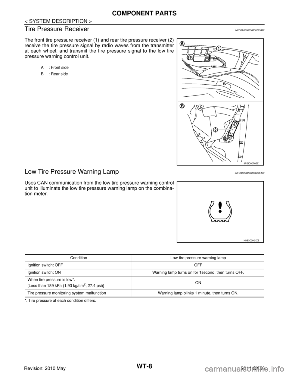
Tire Pressure Receiver
INFOID:0000000006225492
The front tire pressure receiver (1) and rear tire pressure receiver (2)
receive the tire pressure signal by radio waves from the transmitter
at each wheel, and transmit the tire pressure signal to the low tire
pressure warning control unit.
Low Tire Pressure Warning LampINFOID:0000000006225493
Uses CAN communication from the low tire pressure warning control
unit to illuminate the low tire pressure warning lamp on the combina-
tion meter.
*: Tire pressure at each condition differs. A: Front side
B : Rear side
JPEIC0070ZZ
NNEIC0001ZZ
Condition Low tire pr
essure warning lamp
Ignition switch: OFF OFF
Ignition switch: ON Warning lamp turns on for 1second, then turns OFF.
When tire pressure is low*.
[Less than 189 kPa (1.93 kg/cm
2, 27.4 psi)] ON
Tire pressure monitoring system malfunction Warning lamp blinks 1 minute, then turns ON.
Revision: 2010 May2011 QX56
Page 5460 of 5598
WT-10
< SYSTEM DESCRIPTION >
SYSTEM
*: Mainly used for the tire inflation indicator function.
LOW TIRE PRESSURE WARNING LAMP CONTROL CONDITION
Uses CAN communication from the low tire pressure warning control unit to illuminate the low tire pressure
warning lamp on the combination meter.
*: Tire pressure at each condition differs.
HAZARD WARNING LAMP CONTROL CONDITION
The low tire pressure warning control unit transmits a hazard request signal to BCM. BCM blinks the hazard
warning lamp, according to the signal.
The hazard warning lamp blinks under the following conditions.
Condition of Blinking The Hazard Warning Lamp When wake-up of registered wheel has been completed. Refer to WT-28, "Work Procedure".
When ID registration is completed. Refer to WT-29, "
Work Procedure".
During the use of the tire inflation indicator function.
HORN CONTROL CONDITION
The low tire pressure warning control unit transmits a horn request signal to BCM. BCM controls horn sound,
according to the signal.
The horn sounds under the following condition.
Condition of Sounding Horn During the use of tire inflation indicator function.
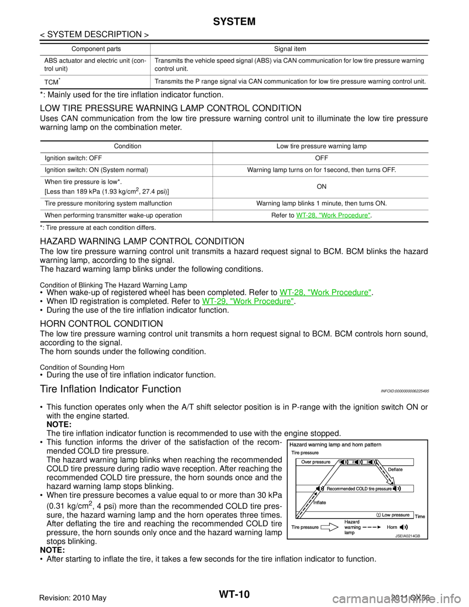
Tire Inflation Indicator FunctionINFOID:0000000006225495
This function operates only when the A/T shift selector position is in P-range with the ignition switch ON or
with the engine started.
NOTE:
The tire inflation indicator function is recommended to use with the engine stopped.
This function informs the driver of the satisfaction of the recom- mended COLD tire pressure.
The hazard warning lamp blinks when reaching the recommended
COLD tire pressure during radio wave reception. After reaching the
recommended COLD tire pressure, the horn sounds once and the
hazard warning lamp stops blinking.
When tire pressure becomes a value equal to or more than 30 kPa
(0.31 kg/cm
2, 4 psi) more than the recommended COLD tire pres-
sure, the hazard warning lamp and the horn operates three times.
After deflating the tire and reaching the recommended COLD tire
pressure, the horn sounds only once and the hazard warning lamp
stops blinking.
NOTE:
After starting to inflate the tire, it takes a few seconds for the tire inflation indicator to function.
ABS actuator and electric unit (con-
trol unit) Transmits the vehicle speed signal (ABS) via CAN communication for low tire pressure warning
control unit.
TCM
*Transmits the P range signal via CAN communication for low tire pressure warning control unit.
Component parts Signal item
Condition Low tire pr
essure warning lamp
Ignition switch: OFF OFF
Ignition switch: ON (System normal) Warning lamp turns on for 1second, then turns OFF.
When tire pressure is low*.
[Less than 189 kPa (1.93 kg/cm
2, 27.4 psi)] ON
Tire pressure monitoring system malfunction Warning lamp blinks 1 minute, then turns ON.
When performing transmitter wake-up operation Refer to WT-28, "
Work Procedure".
JSEIA0214GB
Revision: 2010 May2011 QX56
Page 5461 of 5598

SYSTEMWT-11
< SYSTEM DESCRIPTION >
C
DF
G H
I
J
K L
M A
B
WT
N
O P
If there is no response for approximately 15 seconds or mo re after inflating the tires, cancel the use of the
tire inflation indicator function or move the vehicle approximately 1 m (3.2 ft) backward or forward to try
again. The air filler pressure may be weak or out of service area.
Revision: 2010 May2011 QX56
Page 5475 of 5598
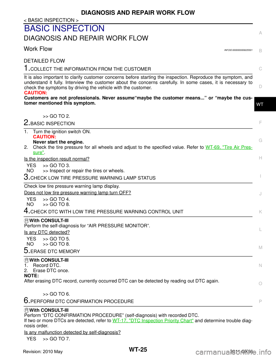
DIAGNOSIS AND REPAIR WORK FLOWWT-25
< BASIC INSPECTION >
C
DF
G H
I
J
K L
M A
B
WT
N
O P
BASIC INSPECTION
DIAGNOSIS AND REPAIR WORK FLOW
Work Flow INFOID:0000000006225501
DETAILED FLOW
1.COLLECT THE INFORMATION FROM THE CUSTOMER
It is also important to clarify customer concerns before starting the inspection. Reproduce the symptom, and
understand it fully. Interview the customer about the concer ns carefully. In some cases, it is necessary to
check the symptoms by driving the vehicle with the customer.
CAUTION:
Customers are not professionals. Never assume“mayb e the customer means...” or “maybe the cus-
tomer mentioned this symptom.
>> GO TO 2.
2.BASIC INSPECTION
1. Turn the ignition switch ON. CAUTION:
Never start the engine.
2. Check the tire pressure for all wheels and adjust to the specified value. Refer to WT-69, "
Tire Air Pres-
sure".
Is the inspection result normal?
YES >> GO TO 3.
NO >> Inspect or repair the tires or wheels.
3.CHECK LOW TIRE PRESSURE WARNING LAMP STATUS
Check low tire pressure warning lamp display.
Does not low tire pressure warning lamp turn OFF?
YES >> GO TO 4.
NO >> GO TO 8.
4.CHECK DTC WITH LOW TIRE PR ESSURE WARNING CONTROL UNIT
With CONSULT-III
Perform the self-diagnosis fo r “AIR PRESSURE MONITOR”.
Is any DTC detected?
YES >> GO TO 5.
NO >> GO TO 8.
5.ERASE DTC MEMORY
With CONSULT-III
1. Record DTC.
2. Erase DTC once.
NOTE:
After erasing DTC record, currently occurr ed DTC can be detected by reading out DTC again.
>> GO TO 6.
6.PERFORM DTC CONFIRMATION PROCEDURE
With CONSULT-III
Perform “DTC CONFIRMATION PROCEDURE” (self-diagnosis) with recorded DTC.
If two or more DTCs are detected, refer to WT-17, "
DTC Inspection Priority Chart" and determine trouble diag-
nosis order.
Is any malfunction detected by self-diagnosis?
YES >> GO TO 7.
Revision: 2010 May2011 QX56