2011 INFINITI QX56 BATTERY
[x] Cancel search: BATTERYPage 5070 of 5598
STR-2
< PRECAUTION >
PRECAUTIONS
PRECAUTION
PRECAUTIONS
Precaution for Supplemental Restraint System (SRS) "AIR BAG" and "SEAT BELT
PRE-TENSIONER"
INFOID:0000000006275515
The Supplemental Restraint System such as “A IR BAG” and “SEAT BELT PRE-TENSIONER”, used along
with a front seat belt, helps to reduce the risk or severi ty of injury to the driver and front passenger for certain
types of collision. This system includes seat belt switch inputs and dual stage front air bag modules. The SRS
system uses the seat belt switches to determine the front air bag deployment, and may only deploy one front
air bag, depending on the severity of a collision and w hether the front occupants are belted or unbelted.
Information necessary to service the system safely is included in the “SRS AIR BAG” and “SEAT BELT” of this
Service Manual.
WARNING:
• To avoid rendering the SRS inopera tive, which could increase the risk of personal injury or death in
the event of a collision that would result in air bag inflation, all maintenance must be performed by
an authorized NISS AN/INFINITI dealer.
Improper maintenance, including in correct removal and installation of the SRS, can lead to personal
injury caused by unintent ional activation of the system. For re moval of Spiral Cable and Air Bag
Module, see the “SRS AIR BAG”.
Do not use electrical test equipmen t on any circuit related to the SRS unless instructed to in this
Service Manual. SRS wiring harnesses can be identi fied by yellow and/or orange harnesses or har-
ness connectors.
PRECAUTIONS WHEN USING POWER TOOLS (AIR OR ELECTRIC) AND HAMMERS
WARNING:
When working near the Air Bag Diagnosis Sensor Unit or other Air Bag System sensors with the ignition ON or engine running, DO NOT use air or electric power tools or strike near the sensor(s)
with a hammer. Heavy vibration could activate the sensor(s) and deploy the air bag(s), possibly
causing serious injury.
When using air or electric power tools or hammers , always switch the ignition OFF, disconnect the
battery, and wait at least 3 minu tes before performing any service.
Precaution Necessary for Steering W heel Rotation after Battery Disconnect
INFOID:0000000006275516
NOTE:
Before removing and installing any control units, first tu rn the push-button ignition switch to the LOCK posi-
tion, then disconnect bot h battery cables.
After finishing work, confirm that all control unit connectors are connected properly, then re-connect both
battery cables.
Always use CONSULT-III to perform self-diagnosis as a part of each function inspection after finishing work.
If a DTC is detected, perform trouble diagnos is according to self-diagnosis results.
For vehicle with steering lock unit, if the battery is disconnected or discharged, the steering wheel will lock and
cannot be turned.
If turning the steering wheel is required with the bat tery disconnected or discharged, follow the operation pro-
cedure below before starting the repair operation.
OPERATION PROCEDURE
1. Connect both battery cables. NOTE:
Supply power using jumper cables if battery is discharged.
2. Turn the push-button ignition switch to ACC position. (At this time, the steering lock will be released.)
3. Disconnect both battery cables. The steering lock wi ll remain released with both battery cables discon-
nected and the steering wheel can be turned.
4. Perform the necessary repair operation.
Revision: 2010 May2011 QX56
Page 5071 of 5598

PRECAUTIONSSTR-3
< PRECAUTION >
C
DE
F
G H
I
J
K L
M A
STR
NP
O
5. When the repair work is completed, re-connect both
battery cables. With the brake pedal released, turn
the push-button ignition switch from ACC position to ON position, then to LOCK position. (The steering
wheel will lock when the push-button ignition switch is turned to LOCK position.)
6. Perform self-diagnosis check of a ll control units using CONSULT-III.
Revision: 2010 May2011 QX56
Page 5073 of 5598
COMPONENT PARTSSTR-5
< SYSTEM DESCRIPTION >
C
DE
F
G H
I
J
K L
M A
STR
NP
O
SYSTEM DESCRIPTION
COMPONENT PARTS
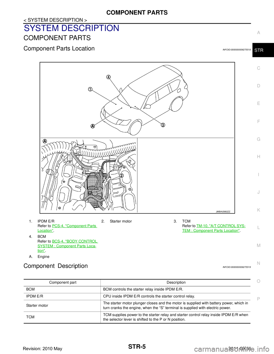
Component Parts LocationINFOID:0000000006275518
Component DescriptionINFOID:0000000006275519
1. IPDM E/R
Refer to PCS-4, "
Component Parts
Location". 2. Starter motor 3. TCM
Refer to TM-10, "
A/T CONTROL SYS-
TEM : Component Parts Location".
4. BCM Refer to BCS-4, "
BODY CONTROL
SYSTEM : Componen t Parts Loca-
tion".
A. Engine
JMBIA2982ZZ
Component part Description
BCM BCM controls the starter relay inside IPDM E/R.
IPDM E/R CPU inside IPDM E/R controls the starter control relay.
Starter motor The starter motor plunger closes and the motor is supplied with battery power, which in
turn cranks the engine, when the “S” terminal is supplied with electric power.
TCM TCM supplies power to the starter relay and starter control relay inside IPDM E/R when
the selector lever is shifted to the P or N position.
Revision: 2010 May2011 QX56
Page 5074 of 5598
STR-6
< SYSTEM DESCRIPTION >
SYSTEM
SYSTEM
System DiagramINFOID:0000000006275520
System DescriptionINFOID:0000000006275521
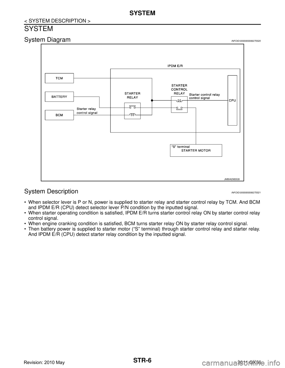
When selector lever is P or N, power is supplied to starter relay and starter control relay by TCM. And BCM
and IPDM E/R (CPU) detect selector lever P/N condition by the inputted signal.
When starter operating condition is satisfied, IPDM E/R tu rns starter control relay ON by starter control relay
control signal.
When engine cranking condition is satisfied, BCM turns starter relay ON by starter relay control signal.
Then battery power is supplied to starter motor (“S” terminal) through starter control relay and starter relay. And IPDM E/R (CPU) detect starter re lay condition by the inputted signal.
JMBIA2983GB
Revision: 2010 May2011 QX56
Page 5080 of 5598
STR-12
< BASIC INSPECTION >
DIAGNOSIS AND REPAIR WORKFLOW
NOTE:
To ensure a complete and thorough diagnosis, the battery, starter motor and alternator test segments must be
done as a set from start to finish.
1.DIAGNOSIS WITH STARTING /CHARGING SYSTEM TESTER
Perform the starting system test with Starting/Char ging System Tester (SST: J-44373). For details and operat-
ing instructions, refer to Technical Service Bulletin.
Te s t r e s u l t
CRANKING VOLTAGE NORMAL>>GO TO 2.
CRANKING VOLTAGE LOW>>GO TO 5.
CHARGE BATTERY>>Perform the slow battery charging procedure. (Initial rate of charge is 10A for 12
hours.) Perform battery test again. Re fer to Technical Service Bulletin.
REPLACE BATTERY>>Before replacing battery, clean t he battery cable clamps and battery posts. Perform
battery test again. Refer to Technical Service Bu lletin. If second test result is “REPLACE BAT-
TERY”, then do so. Perform battery test again to confirm repair.
2.CRANKING CHECK
Check that the starter motor operates correctly.
Does the engine crank normally?
YES >> GO TO 3.
NO >> GO TO 4.
3.ENGINE START CHECK
Check that the engine starts.
Does the engine start?
YES >> Starter motor is OK. INSPECTION END
NO >> Perform further diagnosis of engine mechanical or engine control system. Refer EM and EC sec-
tions. Once resolved, perform battery test again.
4.STARTER MOTOR ACTIVATION
Check that the starter motor operates.
Does the starter motor turn?
YES >> Check ring gear and starter motor drive pinion. Once resolved, perform battery test again.
NO >> GO TO 7.
5.COMPARISON BETWEEN ENGINE COOLANT AND CRANKING VOLTAGE
Compare the engine coolant temperature and the cranking voltage with the specifications.
Minimum Specification of Cranking Voltage Referencing Coolant Temperature
Is the voltage less than the specified value?
YES >> GO TO 7.
NO >> GO TO 6.
6.STARTER OPERATION
Check the starter operation status.
Does the starter motor turn smoothly?
YES >> Starter motor is OK. INSPECTION END
NO >> GO TO 7.
7.“B” TERMINAL CIRCUIT INSPECTION
Check “B” terminal circuit. Refer to STR-14, "
Diagnosis Procedure".
Is
“B” terminal circuit normal?
Engine coolant temperature [ °C ( °F)] Voltage [V]
− 30 to −20 ( −22 to −4) 8.6
− 19 to −10 ( −2 to 14) 9.1
− 9 to 0 (16 to 32) 9.5
More than 1 (More than 34) 9.9
Revision: 2010 May2011 QX56
Page 5081 of 5598
DIAGNOSIS AND REPAIR WORKFLOWSTR-13
< BASIC INSPECTION >
C
DE
F
G H
I
J
K L
M A
STR
NP
O
YES >> GO TO 8.
NO >> Repair as needed.
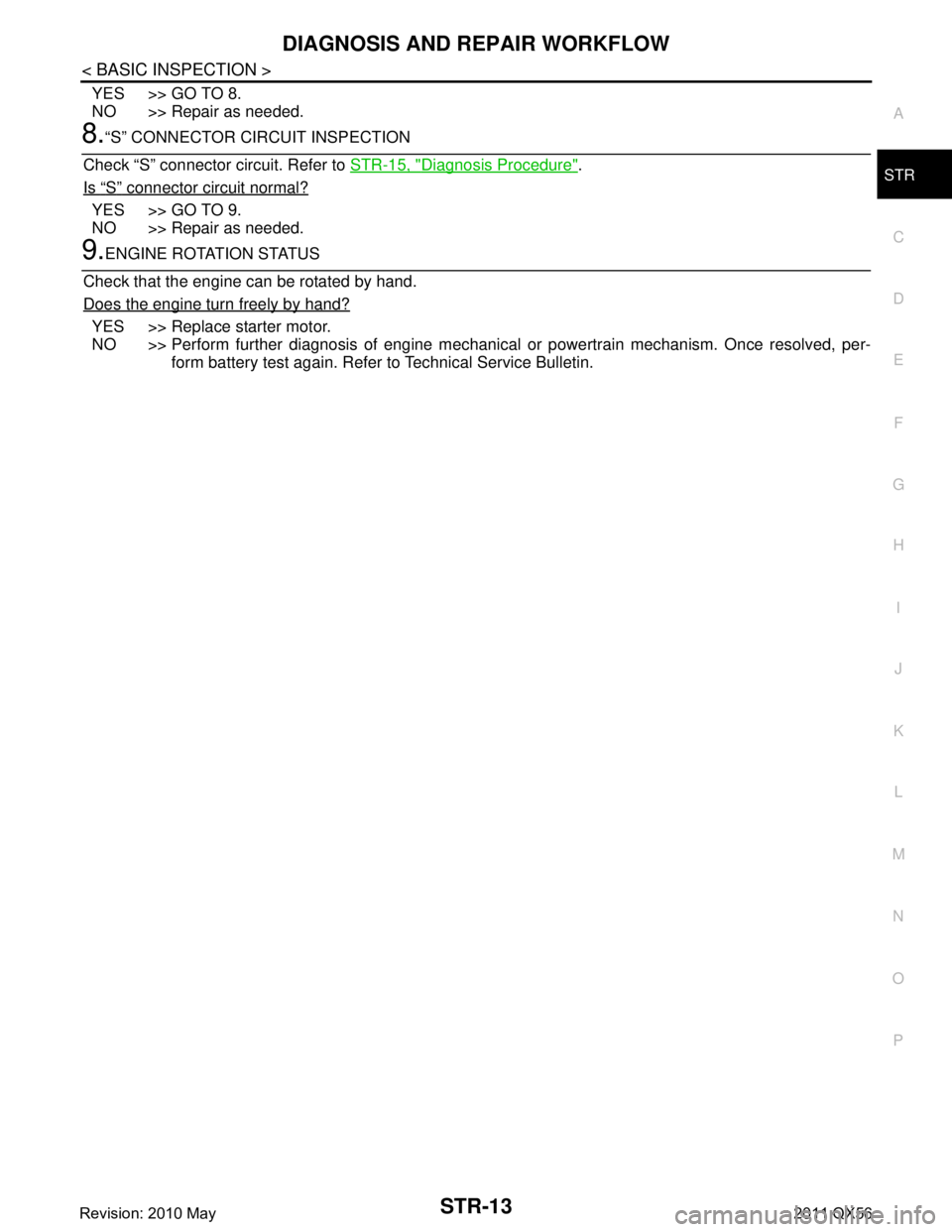
8.“S” CONNECTOR CIRCUIT INSPECTION
Check “S” connector circuit. Refer to STR-15, "
Diagnosis Procedure".
Is
“S” connector circuit normal?
YES >> GO TO 9.
NO >> Repair as needed.
9.ENGINE ROTATION STATUS
Check that the engine can be rotated by hand.
Does the engine turn freely by hand?
YES >> Replace starter motor.
NO >> Perform further diagnosis of engine mechanical or powertrain mechanism. Once resolved, per-
form battery test again. Refer to Technical Service Bulletin.
Revision: 2010 May2011 QX56
Page 5082 of 5598
STR-14
< DTC/CIRCUIT DIAGNOSIS >
B TERMINAL CIRCUIT
DTC/CIRCUIT DIAGNOSIS
B TERMINAL CIRCUIT
Diagnosis ProcedureINFOID:0000000006275524
CAUTION:
Perform diagnosis under the condition that engine cannot start by the following procedure.
1. Remove fuel pump fuse.
2. Crank or start the engine (where possi ble) until the fuel pressure is released.
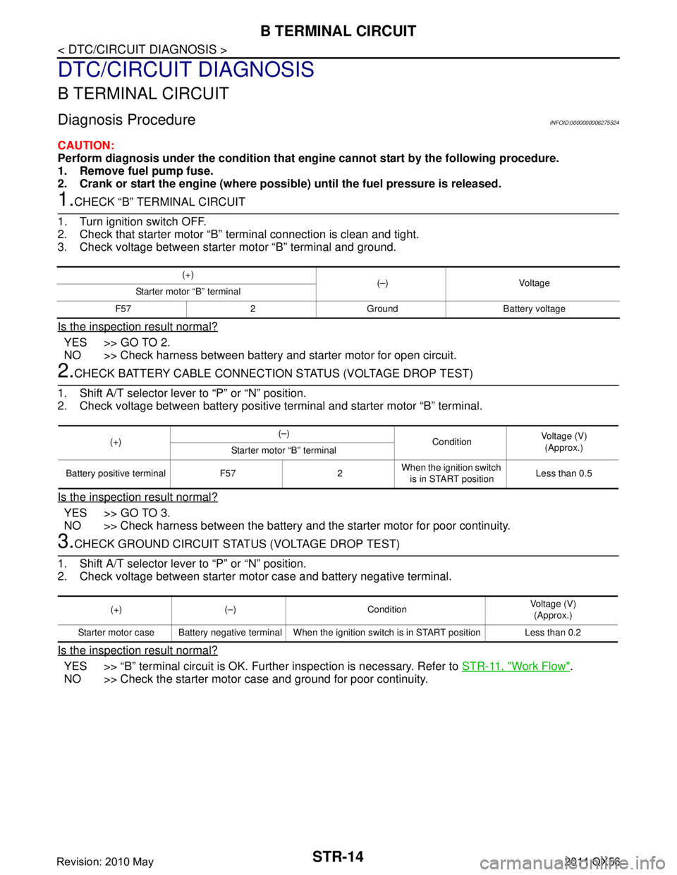
1.CHECK “B” TERMINAL CIRCUIT
1. Turn ignition switch OFF.
2. Check that starter motor “B” terminal connection is clean and tight.
3. Check voltage between starter motor “B” terminal and ground.
Is the inspection result normal?
YES >> GO TO 2.
NO >> Check harness between battery and starter motor for open circuit.
2.CHECK BATTERY CABLE CONNECTION STATUS (VOLTAGE DROP TEST)
1. Shift A/T selector lever to “P” or “N” position.
2. Check voltage between battery positive terminal and starter motor “B” terminal.
Is the inspection result normal?
YES >> GO TO 3.
NO >> Check harness between the battery and the starter motor for poor continuity.
3.CHECK GROUND CIRCUIT STATUS (VOLTAGE DROP TEST)
1. Shift A/T selector lever to “P” or “N” position.
2. Check voltage between starter motor case and battery negative terminal.
Is the inspection result normal?
YES >> “B” terminal circuit is OK. Further inspection is necessary. Refer to STR-11, "Work Flow".
NO >> Check the starter motor case and ground for poor continuity.
(+) (–) Voltage
Starter motor “B” terminal
F57 2 Ground Battery voltage
(+) (–)
ConditionVoltage (V)
(Approx.)
Starter motor “B” terminal
Battery positive terminal F57 2 When the ignition switch
is in START position Less than 0.5
(+) (–) Condition Voltage (V)
(Approx.)
Starter motor case Battery negative terminal When the ignition switch is in START position Less than 0.2
Revision: 2010 May2011 QX56
Page 5083 of 5598
S CONNECTOR CIRCUITSTR-15
< DTC/CIRCUIT DIAGNOSIS >
C
DE
F
G H
I
J
K L
M A
STR
NP
O
S CONNECTOR CIRCUIT
Diagnosis ProcedureINFOID:0000000006275525
CAUTION:
Perform diagnosis under the cond
ition that engine cannot start by the following procedure.
1. Remove fuel pump fuse.
2. Crank or start the engine (where possi ble) until the fuel pressure is released.
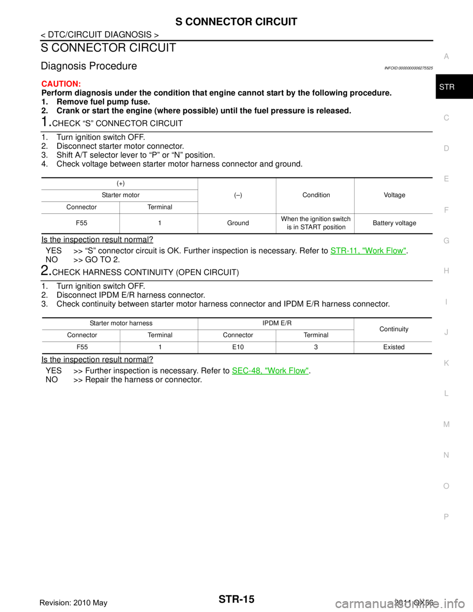
1.CHECK “S” CONNECTOR CIRCUIT
1. Turn ignition switch OFF.
2. Disconnect starter motor connector.
3. Shift A/T selector lever to “P” or “N” position.
4. Check voltage between starter motor harness connector and ground.
Is the inspection result normal?
YES >> “S” connector circuit is OK. Furt her inspection is necessary. Refer to STR-11, "Work Flow".
NO >> GO TO 2.
2.CHECK HARNESS CONTI NUITY (OPEN CIRCUIT)
1. Turn ignition switch OFF.
2. Disconnect IPDM E/R harness connector.
3. Check continuity between starter motor harness connector and IPDM E/R harness connector.
Is the inspection result normal?
YES >> Further inspection is necessary. Refer to SEC-48, "Work Flow".
NO >> Repair the harness or connector.
(+)
(–) Condition Voltage
Starter motor
Connector Terminal
F55 1 Ground When the ignition switch
is in START position Battery voltage
Starter motor harness IPDM E/R
Continuity
Connector Terminal Connector Terminal
F55 1 E10 3 Existed
Revision: 2010 May2011 QX56