Page 5405 of 5598

WCS
WCS-1
DRIVER INFORMATION & MULTIMEDIA
C
DE
F
G H
I
J
K L
M B
SECTION WCS
A
O P
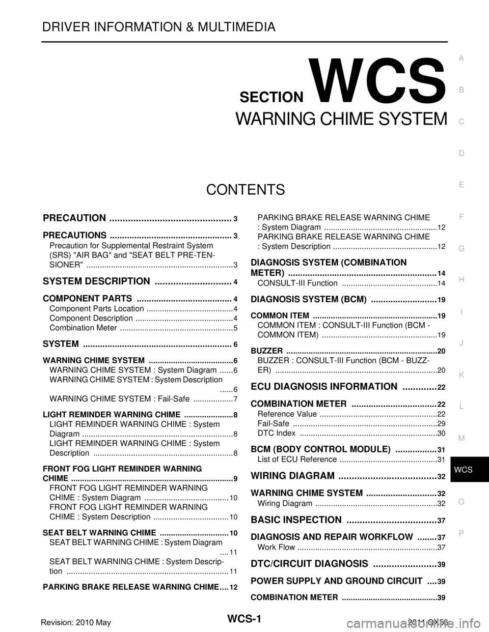
CONTENTS
WARNING CHIME SYSTEM
PRECAUTION ................ ...............................3
PRECAUTIONS .............................................. .....3
Precaution for Supplemental Restraint System
(SRS) "AIR BAG" and "SEAT BELT PRE-TEN-
SIONER" ............................................................. ......
3
SYSTEM DESCRIPTION ..............................4
COMPONENT PARTS ................................... .....4
Component Parts Location .................................. ......4
Component Description .............................................4
Combination Meter ....................................................5
SYSTEM ..............................................................6
WARNING CHIME SYSTEM .......................................6
WARNING CHIME SYSTEM : System Diagram . ......6
WARNING CHIME SYSTEM : System Description
......
6
WARNING CHIME SYSTEM : Fail-Safe ...................7
LIGHT REMINDER WARNING CHIME ................. ......8
LIGHT REMINDER WARNING CHIME : System
Diagram .....................................................................
8
LIGHT REMINDER WARNING CHIME : System
Description ................................................................
8
FRONT FOG LIGHT REMINDER WARNING
CHIME .................................................................... ......
9
FRONT FOG LIGHT REMINDER WARNING
CHIME : System Diagram .......................................
10
FRONT FOG LIGHT REMINDER WARNING
CHIME : System Description ...................................
10
SEAT BELT WARNING CHIME ............................ ....10
SEAT BELT WARNING CHIME : System Diagram
....
11
SEAT BELT WARNING CHIME : System Descrip-
tion ...................................................................... ....
11
PARKING BRAKE RELEASE WARNING CHIME ....12
PARKING BRAKE RELEASE WARNING CHIME
: System Diagram ................................................ ....
12
PARKING BRAKE RELEASE WARNING CHIME
: System Description ................................................
12
DIAGNOSIS SYSTEM (COMBINATION
METER) .............................................................
14
CONSULT-III Function ............................................14
DIAGNOSIS SYSTEM (BCM) ...........................19
COMMON ITEM ..................................................... ....19
COMMON ITEM : CONSULT-III Function (BCM -
COMMON ITEM) .....................................................
19
BUZZER ................................................................. ....20
BUZZER : CONSULT-III Function (BCM - BUZZ-
ER) ..........................................................................
20
ECU DIAGNOSIS INFORMATION ..............22
COMBINATION METER ...................................22
Reference Value .................................................. ....22
Fail-Safe ..................................................................29
DTC Index ...............................................................30
BCM (BODY CONTROL MODULE) .................31
List of ECU Reference .............................................31
WIRING DIAGRAM ......................................32
WARNING CHIME SYSTEM .............................32
Wiring Diagram .................................................... ....32
BASIC INSPECTION ...................................37
DIAGNOSIS AND REPAIR WORKFLOW ........37
Work Flow ............................................................ ....37
DTC/CIRCUIT DIAGNOSIS .........................39
POWER SUPPLY AND GROUND CIRCUIT ....39
COMBINATION METER ........................................ ....39
Revision: 2010 May2011 QX56
Page 5407 of 5598

WCS
PRECAUTIONSWCS-3
< PRECAUTION >
C
DE
F
G H
I
J
K L
M B A
O P
PRECAUTION
PRECAUTIONS
Precaution for Supplemental Restraint System (SRS) "AIR BAG" and "SEAT BELT
PRE-TENSIONER"
INFOID:0000000006369725
The Supplemental Restraint System such as “A IR BAG” and “SEAT BELT PRE-TENSIONER”, used along
with a front seat belt, helps to reduce the risk or severi ty of injury to the driver and front passenger for certain
types of collision. This system includes seat belt switch inputs and dual stage front air bag modules. The SRS
system uses the seat belt switches to determine the front air bag deployment, and may only deploy one front
air bag, depending on the severity of a collision and whether the front occupants are belted or unbelted.
Information necessary to service the system safely is included in the “SRS AIR BAG” and “SEAT BELT” of this
Service Manual.
WARNING:
• To avoid rendering the SRS inoper ative, which could increase the risk of personal injury or death in
the event of a collision that would result in air ba g inflation, all maintenance must be performed by
an authorized NISSAN/INFINITI dealer.
Improper maintenance, including in correct removal and installation of the SRS, can lead to personal
injury caused by unintentional act ivation of the system. For removal of Spiral Cable and Air Bag
Module, see the “SRS AIR BAG”.
Do not use electrical test equipm ent on any circuit related to the SRS unless instructed to in this
Service Manual. SRS wiring harnesses can be identi fied by yellow and/or orange harnesses or har-
ness connectors.
PRECAUTIONS WHEN USING POWER TOOLS (AIR OR ELECTRIC) AND HAMMERS
WARNING:
When working near the Air Bag Diagnosis Sensor Unit or other Air Bag System sensors with the
ignition ON or engine running, DO NOT use air or electric power tools or strike near the sensor(s)
with a hammer. Heavy vibration could activate the sensor(s) and deploy the air bag(s), possibly
causing serious injury.
When using air or electric power tools or hammers , always switch the ignition OFF, disconnect the
battery, and wait at least 3 minutes before performing any service.
Revision: 2010 May2011 QX56
Page 5436 of 5598
WCS-32
< WIRING DIAGRAM >
WARNING CHIME SYSTEM
WIRING DIAGRAM
WARNING CHIME SYSTEM
Wiring DiagramINFOID:0000000006222525
JCNWM4806GB
Revision: 2010 May2011 QX56
Page 5437 of 5598
WCS
WARNING CHIME SYSTEMWCS-33
< WIRING DIAGRAM >
C
DE
F
G H
I
J
K L
M B A
O P
JCNWM4807GB
Revision: 2010 May2011 QX56
Page 5438 of 5598
WCS-34
< WIRING DIAGRAM >
WARNING CHIME SYSTEM
JCNWM4808GB
Revision: 2010 May2011 QX56
Page 5439 of 5598
WCS
WARNING CHIME SYSTEMWCS-35
< WIRING DIAGRAM >
C
DE
F
G H
I
J
K L
M B A
O P
JCNWM4809GB
Revision: 2010 May2011 QX56
Page 5440 of 5598
WCS-36
< WIRING DIAGRAM >
WARNING CHIME SYSTEM
JCNWM4810GB
Revision: 2010 May2011 QX56
Page 5451 of 5598

WT-1
SUSPENSION
C
DF
G H
I
J
K L
M
SECTION WT
A
B
WT
N
O PCONTENTS
ROAD WHEELS & TIRES
PRECAUTION ................ ...............................3
PRECAUTIONS .............................................. .....3
Precaution for Supplemental Restraint System
(SRS) "AIR BAG" and "SEAT BELT PRE-TEN-
SIONER" ............................................................. ......
3
Precaution Necessary for Steering Wheel Rota-
tion after Battery Disconnect .....................................
3
Service Notice or Precautions for TPMS ...................4
Service Notice or Precautions for Road Wheel .........4
PREPARATION ............................................5
PREPARATION .............................................. .....5
Special Service Tools .......................................... ......5
Commercial Service Tools ........................................5
SYSTEM DESCRIPTION ..............................6
COMPONENT PARTS ................................... .....6
Component Parts Location .................................. ......6
Component Description .............................................7
Low Tire Pressure Warning Control Unit ...................7
Transmitter ................................................................7
Tire Pressure Receiver .............................................8
Low Tire Pressure Warning Lamp .............................8
SYSTEM ..............................................................9
System Description ............................................. ......9
Tire Inflation Indicator Function ...............................10
DIAGNOSIS SYSTEM (LOW TIRE PRES-
SURE WARNING CONTROL UNIT) ..................
12
CONSULT-III Function ........................................ ....12
ECU DIAGNOSIS INFORMATION ..............14
LOW TIRE PRESSURE WARNING CON-
TROL UNIT ..................................................... ....
14
Reference Value ................................................. ....14
DTC Inspection Priority Chart .................................17
DTC Index ...............................................................18
WIRING DIAGRAM ......................................19
TIRE PRESSURE MONITORING SYSTEM ......19
Wiring Diagram .................................................... ....19
BASIC INSPECTION ...................................25
DIAGNOSIS AND REPAIR WORK FLOW .......25
Work Flow ............................................................ ....25
ADDITIONAL SERVICE WHEN REPLACING
LOW TIRE PRESSURE WARNING CON-
TROL UNIT ........................................................
27
Description ...............................................................27
Work Procedure .......................................................27
TRANSMITTER WAKE UP OPERATION .........28
Description ...............................................................28
Work Procedure .......................................................28
ID REGISTRATION ...........................................29
Description ...............................................................29
Work Procedure .......................................................29
DTC/CIRCUIT DIAGNOSIS .........................31
C1704, C1705, C1706, C1707 LOW TIRE
PRESSURE .......................................................
31
DTC Logic ............................................................ ....31
Diagnosis Procedure ...............................................31
C1708, C1709, C1710, C1711 TRANSMITTER
(NO DATA) ........................................................
33
DTC Logic ............................................................ ....33
Diagnosis Procedure ...............................................33
C1716, C1717, C1718, C1719 TRANSMITTER
(PRESSURE DATA) ..........................................
37
DTC Logic ............................................................ ....37
Diagnosis Procedure ...............................................37
C1728 RECEIVER ID ........................................39
Revision: 2010 May2011 QX56