Page 5405 of 5598

WCS
WCS-1
DRIVER INFORMATION & MULTIMEDIA
C
DE
F
G H
I
J
K L
M B
SECTION WCS
A
O P
CONTENTS
WARNING CHIME SYSTEM
PRECAUTION ................ ...............................3
PRECAUTIONS .............................................. .....3
Precaution for Supplemental Restraint System
(SRS) "AIR BAG" and "SEAT BELT PRE-TEN-
SIONER" ............................................................. ......
3
SYSTEM DESCRIPTION ..............................4
COMPONENT PARTS ................................... .....4
Component Parts Location .................................. ......4
Component Description .............................................4
Combination Meter ....................................................5
SYSTEM ..............................................................6
WARNING CHIME SYSTEM .......................................6
WARNING CHIME SYSTEM : System Diagram . ......6
WARNING CHIME SYSTEM : System Description
......
6
WARNING CHIME SYSTEM : Fail-Safe ...................7
LIGHT REMINDER WARNING CHIME ................. ......8
LIGHT REMINDER WARNING CHIME : System
Diagram .....................................................................
8
LIGHT REMINDER WARNING CHIME : System
Description ................................................................
8
FRONT FOG LIGHT REMINDER WARNING
CHIME .................................................................... ......
9
FRONT FOG LIGHT REMINDER WARNING
CHIME : System Diagram .......................................
10
FRONT FOG LIGHT REMINDER WARNING
CHIME : System Description ...................................
10
SEAT BELT WARNING CHIME ............................ ....10
SEAT BELT WARNING CHIME : System Diagram
....
11
SEAT BELT WARNING CHIME : System Descrip-
tion ...................................................................... ....
11
PARKING BRAKE RELEASE WARNING CHIME ....12
PARKING BRAKE RELEASE WARNING CHIME
: System Diagram ................................................ ....
12
PARKING BRAKE RELEASE WARNING CHIME
: System Description ................................................
12
DIAGNOSIS SYSTEM (COMBINATION
METER) .............................................................
14
CONSULT-III Function ............................................14
DIAGNOSIS SYSTEM (BCM) ...........................19
COMMON ITEM ..................................................... ....19
COMMON ITEM : CONSULT-III Function (BCM -
COMMON ITEM) .....................................................
19
BUZZER ................................................................. ....20
BUZZER : CONSULT-III Function (BCM - BUZZ-
ER) ..........................................................................
20
ECU DIAGNOSIS INFORMATION ..............22
COMBINATION METER ...................................22
Reference Value .................................................. ....22
Fail-Safe ..................................................................29
DTC Index ...............................................................30
BCM (BODY CONTROL MODULE) .................31
List of ECU Reference .............................................31
WIRING DIAGRAM ......................................32
WARNING CHIME SYSTEM .............................32
Wiring Diagram .................................................... ....32
BASIC INSPECTION ...................................37
DIAGNOSIS AND REPAIR WORKFLOW ........37
Work Flow ............................................................ ....37
DTC/CIRCUIT DIAGNOSIS .........................39
POWER SUPPLY AND GROUND CIRCUIT ....39
COMBINATION METER ........................................ ....39
Revision: 2010 May2011 QX56
Page 5410 of 5598

WCS-6
< SYSTEM DESCRIPTION >
SYSTEM
SYSTEM
WARNING CHIME SYSTEM
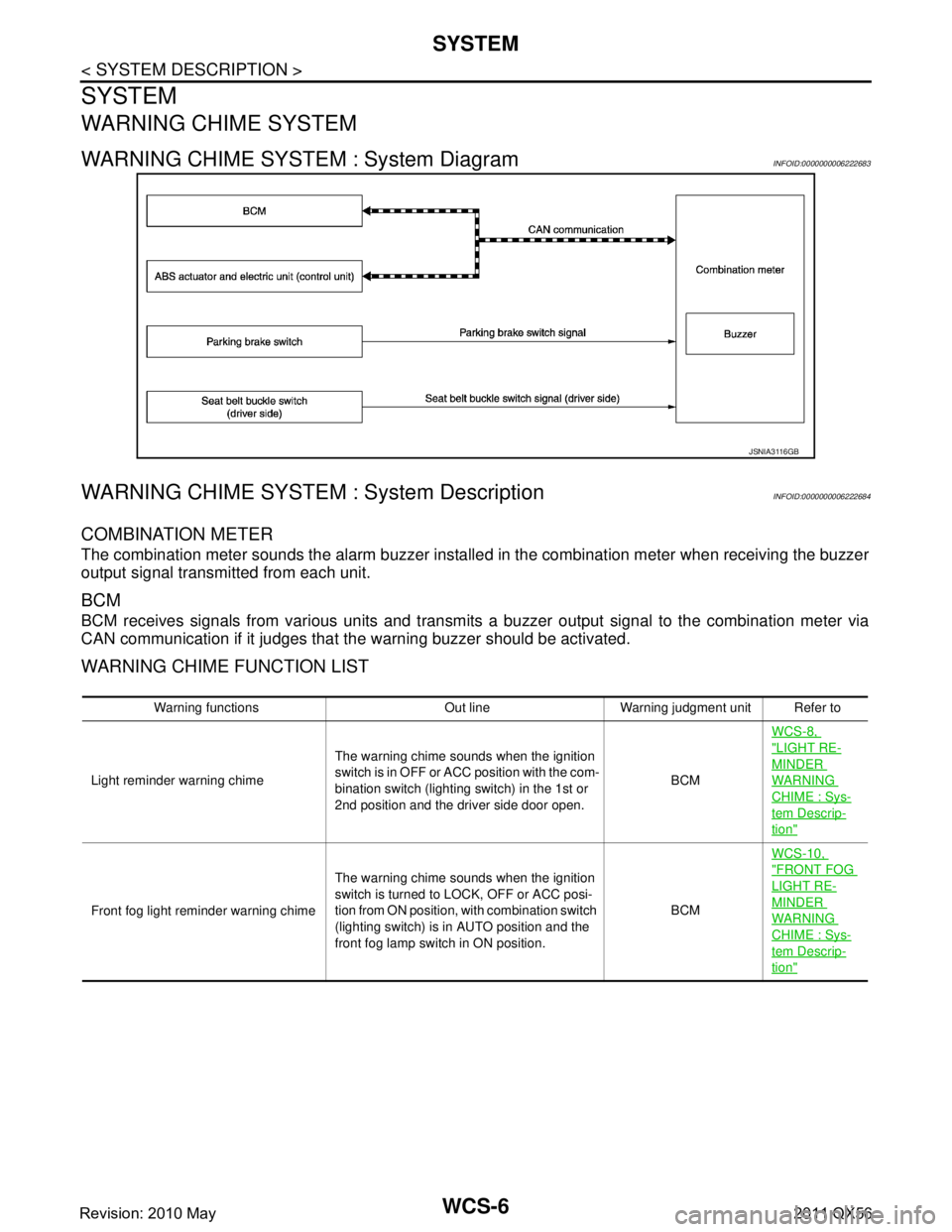
WARNING CHIME SYSTEM : System DiagramINFOID:0000000006222683
WARNING CHIME SYSTEM : System DescriptionINFOID:0000000006222684
COMBINATION METER
The combination meter sounds the alarm buzzer install ed in the combination meter when receiving the buzzer
output signal transmitted from each unit.
BCM
BCM receives signals from various units and transmits a buzzer output signal to the combination meter via
CAN communication if it judges that the warning buzzer should be activated.
WARNING CHIME FUNCTION LIST
JSNIA3116GB
Warning functions Out line Warning judgment unit Refer to
Light reminder warning chime The warning chime sounds when the ignition
s w i t c h i s i n O F F o r A C C p o s i t i o n w i t h t h e c o m -
bination switch (lighting switch) in the 1st or
2nd position and the driver side door open. BCMWCS-8,
"LIGHT RE-
MINDER
WARNING
CHIME : Sys-
tem Descrip-
tion"
Front fog light reminder warning chime
The warning chime sounds when the ignition
switch is turned to LOCK, OFF or ACC posi-
tion from ON position, with combination switch
(lighting switch) is in AUTO position and the
front fog lamp switch in ON position. BCMWCS-10,
"FRONT FOG
LIGHT RE-
MINDER
WARNING
CHIME : Sys-
tem Descrip-
tion"
Revision: 2010 May2011 QX56
Page 5412 of 5598

WCS-8
< SYSTEM DESCRIPTION >
SYSTEM
LIGHT REMINDER WARNING CHIME
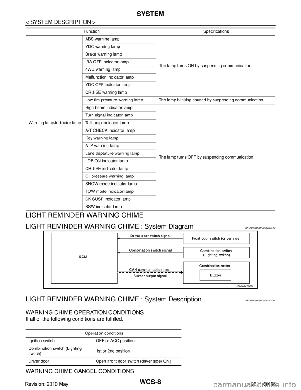
LIGHT REMINDER WARNING CHIME : System DiagramINFOID:0000000006222543
LIGHT REMINDER WARNING CHIME : System DescriptionINFOID:0000000006222544
WARNING CHIME OPERATION CONDITIONS
If all of the following conditions are fulfilled.
WARNING CHIME CANCEL CONDITIONS
Warning lamp/indicator lampABS warning lamp
The lamp turns ON by suspending communication.
VDC warning lamp
Brake warning lamp
IBA OFF indicator lamp
4WD warning lamp
Malfunction indicator lamp
VDC OFF indicator lamp
CRUISE warning lamp
Low tire pressure warning lamp The lamp blinking caused by suspending communication.
High beam indicator lamp
The lamp turns OFF by suspending communication.
Turn signal indicator lamp
Tail lamp indicator lamp
A/T CHECK indicator lamp
Key warning lamp
ATP warning lamp
Lane departure warning lamp
LDP ON indicator lamp
CRUISE indicator lamp
Oil pressure warning lamp
SNOW mode indicator lamp
TOW mode indicator lamp
CK SUSP indicator lamp
BSW indicator lamp
Function Specifications
JSNIA2421GB
Operation conditions
Ignition switch OFF or ACC position
Combination switch (Lighting
switch) 1st or 2nd position
Driver door Open [front door switch (driver side) ON]
Revision: 2010 May2011 QX56
Page 5414 of 5598

WCS-10
< SYSTEM DESCRIPTION >
SYSTEM
FRONT FOG LIGHT REMINDER WARNING CHIME : System Diagram
INFOID:0000000006222545
FRONT FOG LIGHT REMINDER WARNING CHIME : System DescriptionINFOID:0000000006222546
WARNING CHIME OPERATION CONDITIONS
Warning chime sounds during 2 seconds when the ignition sw itch is in LOCK, OFF or ACC position, if all of
below operation conditions is met.
SIGNAL PATH
1. BCM requires warning chime output to combination meter when it judges front fog light reminder warning
chime is necessary from signals below.
2. Combination meter sounds integrated buzzer, following the warning chime output requirement (below sig- nal) from BCM.
TIMING CHART
SEAT BELT WARNING CHIME
JSNIA3117GB
Operation conditions
Ignition switch ON position
Combination switch (Lighting
switch) AUTO position and front fog lamp switch ON
position
Signal name Signal path
Ignition switch signal —
Combination switch signal Combination switch (Lighting switch) BCM
Signal name Signal path
Buzzer output signal BCM Combination meter
JSNIA3110GB
Revision: 2010 May2011 QX56
Page 5415 of 5598

WCS
SYSTEMWCS-11
< SYSTEM DESCRIPTION >
C
DE
F
G H
I
J
K L
M B A
O P
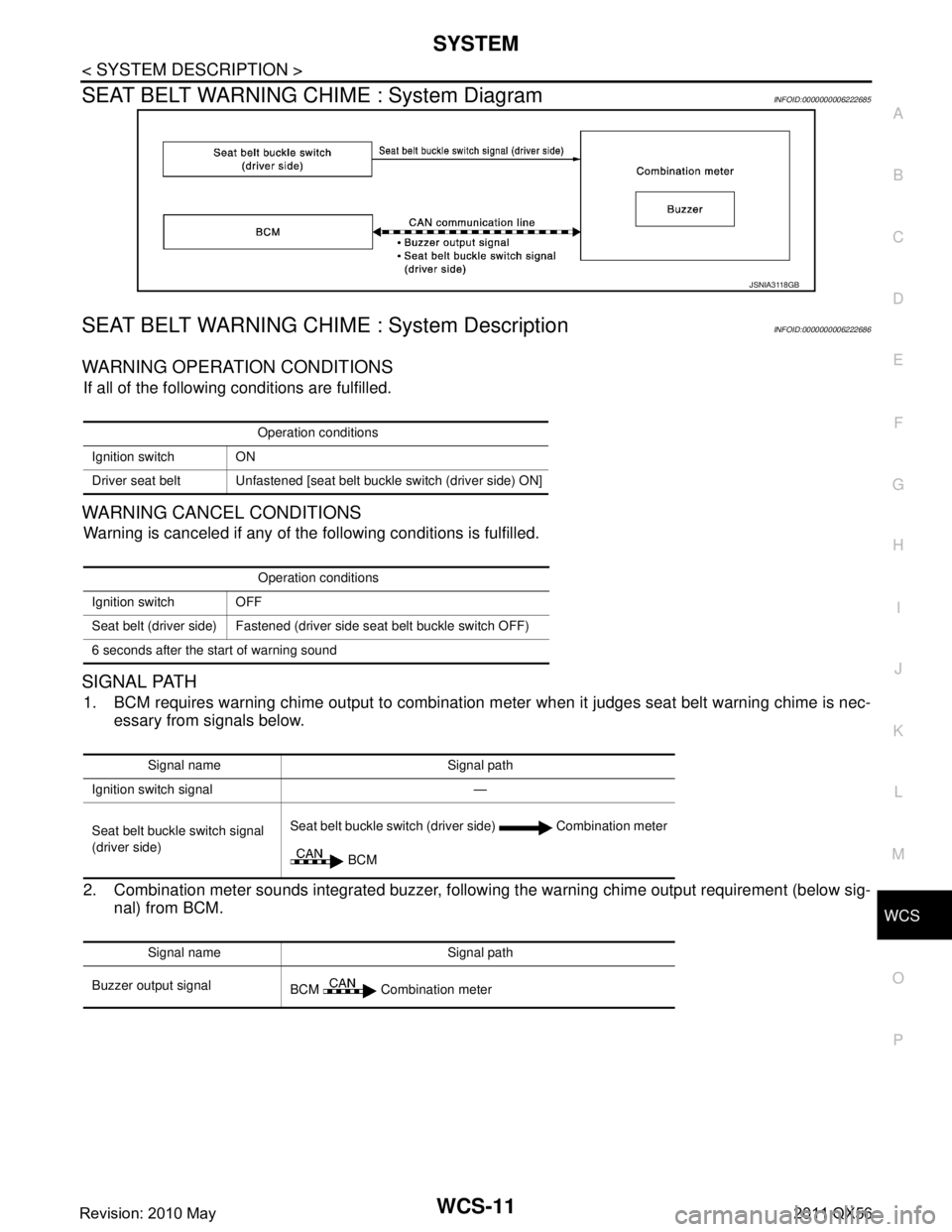
SEAT BELT WARNING CHIME : System DiagramINFOID:0000000006222685
SEAT BELT WARNING CHIME : System DescriptionINFOID:0000000006222686
WARNING OPERATION CONDITIONS
If all of the following conditions are fulfilled.
WARNING CANCEL CONDITIONS
Warning is canceled if any of t he following conditions is fulfilled.
SIGNAL PATH
1. BCM requires warning chime output to combination meter when it judges seat belt warning chime is nec-
essary from signals below.
2. Combination meter sounds integrated buzzer, followi ng the warning chime output requirement (below sig-
nal) from BCM.
JSNIA3118GB
Operation conditions
Ignition switch ON
Driver seat belt Unfastened [seat belt buckle switch (driver side) ON]
Operation conditions
Ignition switch OFF
Seat belt (driver side) Fastened (driver side seat belt buckle switch OFF)
6 seconds after the start of warning sound
Signal name Signal path
Ignition switch signal —
Seat belt buckle switch signal
(driver side) Seat belt buckle switch (driver side) Combination meter
BCM
Signal name Signal path
Buzzer output signal BCM Combination meter
Revision: 2010 May2011 QX56
Page 5416 of 5598
WCS-12
< SYSTEM DESCRIPTION >
SYSTEM
TIMING CHART
SOUND SPECIFICATION
PARKING BRAKE RELEASE WARNING CHIME
PARKING BRAKE RELEASE WARNING CHIME : System DiagramINFOID:0000000006222547
PARKING BRAKE RELEASE WARNING CHIME : System DescriptionINFOID:0000000006222548
WARNING OPERATION CONDITIONS
If all of the following conditions are fulfilled.
WARNING CANCEL CONDITIONS
Warning is canceled if any of the following conditions are fulfilled.
JSNIA3123GB
J S N I A 3 111 G B
JSNIA2422GB
Operation conditions
Ignition switch ON
Parking brake During the operation (parking brake switch ON)
Vehicle speed Approximately 7 km/h (4.3 MPH) or more
Revision: 2010 May2011 QX56
Page 5436 of 5598
WCS-32
< WIRING DIAGRAM >
WARNING CHIME SYSTEM
WIRING DIAGRAM
WARNING CHIME SYSTEM
Wiring DiagramINFOID:0000000006222525
JCNWM4806GB
Revision: 2010 May2011 QX56
Page 5437 of 5598
WCS
WARNING CHIME SYSTEMWCS-33
< WIRING DIAGRAM >
C
DE
F
G H
I
J
K L
M B A
O P
JCNWM4807GB
Revision: 2010 May2011 QX56