Page 5472 of 5598
WT-22
< WIRING DIAGRAM >
TIRE PRESSURE MONITORING SYSTEM
JCEWM0217GB
Revision: 2010 May2011 QX56
Page 5473 of 5598
TIRE PRESSURE MONITORING SYSTEMWT-23
< WIRING DIAGRAM >
C
DF
G H
I
J
K L
M A
B
WT
N
O P
JCEWM0218GB
Revision: 2010 May2011 QX56
Page 5474 of 5598
WT-24
< WIRING DIAGRAM >
TIRE PRESSURE MONITORING SYSTEM
JCEWM0219GB
Revision: 2010 May2011 QX56
Page 5520 of 5598

WW-1
DRIVER CONTROLS
C
DE
F
G H
I
J
K
M
SECTION WW
A
B
WW
N
O P
CONTENTS
WIPER & WASHER
PRECAUTION ................ ...............................3
PRECAUTIONS .............................................. .....3
Precaution for Supplemental Restraint System
(SRS) "AIR BAG" and "SEAT BELT PRE-TEN-
SIONER" ............................................................. ......
3
Precaution Necessary for Steering Wheel Rota-
tion after Battery Disconnect .....................................
3
Precaution for Procedure without Cowl Top Cover ......4
SYSTEM DESCRIPTION ..............................5
COMPONENT PARTS ................................... .....5
Component Parts Location .................................. ......5
Component Description ............................................6
Washer Switch ..........................................................6
SYSTEM ..............................................................7
FRONT WIPER AND WASHER SYSTEM ............. ......7
FRONT WIPER AND WASHER SYSTEM : Sys-
tem Diagram ..............................................................
7
FRONT WIPER AND WASHER SYSTEM : Sys-
tem Description .........................................................
7
FRONT WIPER AND WASHER SYSTEM : Fail-
safe ...........................................................................
9
REAR WIPER AND WASHER SYSTEM ............... ....10
REAR WIPER AND WASHER SYSTEM : System
Diagram ...................................................................
10
REAR WIPER AND WASHER SYSTEM : System
Description ..............................................................
10
REAR WIPER AND WASHER SYSTEM :
Fail Safe .................................................................
12
HEADLAMP WASHER SYSTEM .......................... ....12
HEADLAMP WASHER SYSTEM : System Dia-
gram ........................................................................
13
HEADLAMP WASHER SYSTEM : System De-
scription ...................................................................
13
DIAGNOSIS SYSTEM (BCM) ............................14
COMMON ITEM ..................................................... ....14
COMMON ITEM : CONSULT-III Function (BCM -
COMMON ITEM) .....................................................
14
WIPER .................................................................... ....15
WIPER : CONSULT-III Function (BCM - WIPER) ....15
DIAGNOSIS SYSTEM (IPDM E/R) ...................18
Diagnosis Description ..............................................18
CONSULT-III Function (IPDM E/R) .........................20
ECU DIAGNOSIS INFORMATION ..............23
BCM, IPDM E/R .................................................23
List of ECU Reference ......................................... ....23
WIRING DIAGRAM ......................................24
WIPER AND WASHER SYSTEM .....................24
Wiring Diagram .................................................... ....24
BASIC INSPECTION ...................................33
DIAGNOSIS AND REPAIR WORKFLOW ........33
Work Flow ............................................................ ....33
DTC/CIRCUIT DIAGNOSIS .........................35
WIPER AND WASHER FUSE ...........................35
Diagnosis Procedure ........................................... ....35
FRONT WIPER MOTOR LO CIRCUIT ..............36
Component Function Check ....................................36
Diagnosis Procedure ...............................................36
FRONT WIPER MOTOR HI CIRCUIT ...............37
Component Function Check ....................................37
Diagnosis Procedure ...............................................37
FRONT WIPER AUTO STOP SIGNAL CIR-
CUIT ..................................................................
38
Component Function Check ....................................38
Diagnosis Procedure ...............................................38
Revision: 2010 May2011 QX56
Page 5526 of 5598

SYSTEMWW-7
< SYSTEM DESCRIPTION >
C
DE
F
G H
I
J
K
M A
B
WW
N
O P
SYSTEM
FRONT WIPER AND WASHER SYSTEM
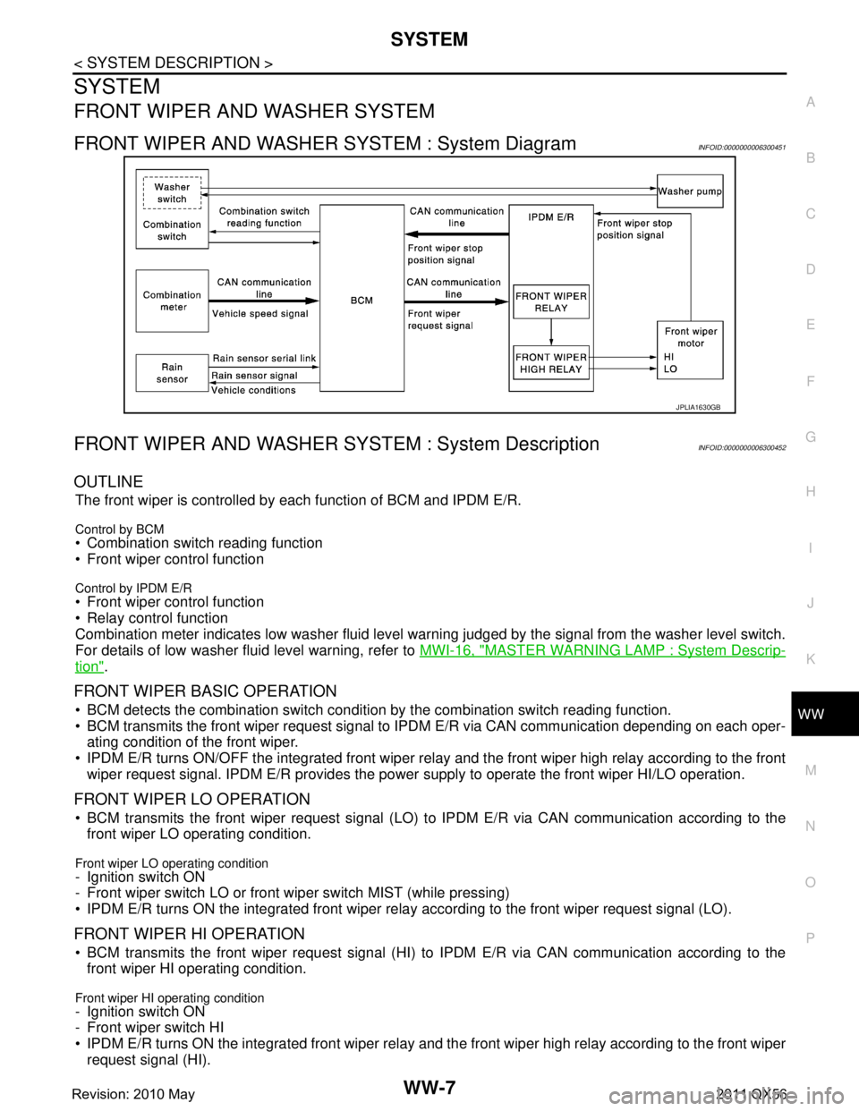
FRONT WIPER AND WASHER SYSTEM : System DiagramINFOID:0000000006300451
FRONT WIPER AND WASHER S YSTEM : System DescriptionINFOID:0000000006300452
OUTLINE
The front wiper is controlled by each function of BCM and IPDM E/R.
Control by BCM
Combination switch reading function
Front wiper control function
Control by IPDM E/R
Front wiper control function
Relay control function
Combination meter indicates low washer fluid level warning judged by the signal from the washer level switch.
For details of low washer fluid level warning, refer to MWI-16, "
MASTER WARNING LAMP : System Descrip-
tion".
FRONT WIPER BASIC OPERATION
BCM detects the combination switch condition by the combination switch reading function.
BCM transmits the front wiper request signal to IPDM E/R via CAN communication depending on each oper-
ating condition of the front wiper.
IPDM E/R turns ON/OFF the integrated front wiper rela y and the front wiper high relay according to the front
wiper request signal. IPDM E/R provides the power supply to operate the front wiper HI/LO operation.
FRONT WIPER LO OPERATION
BCM transmits the front wiper request signal (LO) to IPDM E/R via CAN communication according to the
front wiper LO operating condition.
Front wiper LO operating condition
- Ignition switch ON
- Front wiper switch LO or front wiper switch MIST (while pressing)
IPDM E/R turns ON the integrated front wiper rela y according to the front wiper request signal (LO).
FRONT WIPER HI OPERATION
BCM transmits the front wiper request signal (HI) to IPDM E/R via CAN communication according to the
front wiper HI operating condition.
Front wiper HI operating condition
- Ignition switch ON
- Front wiper switch HI
IPDM E/R turns ON the integrated front wiper relay and the front wiper high relay according to the front wiper
request signal (HI).
JPLIA1630GB
Revision: 2010 May2011 QX56
Page 5529 of 5598

WW-10
< SYSTEM DESCRIPTION >
SYSTEM
IPDM E/R detects front wiper stop position by a front wiper stop position signal.
When a front wiper stop position signal is in the conditi ons listed below, IPDM E/R stops power supply to wiper
after repeating a front wiper 10 seconds activation and 20 seconds stop five times.
NOTE:
This operation status can be confirmed on the IPDM E/ R “Data Monitor” that displays “BLOCK” for the item
“WIP PROT” while the wiper is stopped.
BCM
BCM detects the rain sensor serial link error and the light & rain sensor malfunction.
BCM controls the following fail-safe when light & rain sensor has a malfunction.
Fail-safe Control
Front wiper control
- Front wiper switch AUTO and sensing rain drop: The c ondition just before the activation of fail-safe is main-
tained until the front wiper switch is turned OFF.
- Front wiper switch AUTO and not sensing rain drop: Front wiper is LO operation until the front wiper switch is
turned off.
REAR WIPER AND WASHER SYSTEM
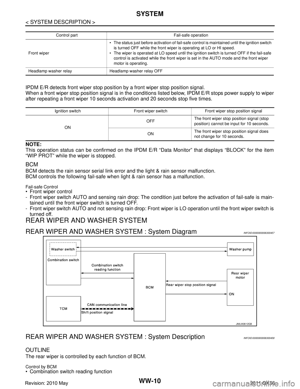
REAR WIPER AND WASHER SYSTEM : System DiagramINFOID:0000000006300457
REAR WIPER AND WASHER S YSTEM : System DescriptionINFOID:0000000006300458
OUTLINE
The rear wiper is controlled by each function of BCM.
Control by BCM
Combination switch reading function
Control part Fail-safe operation
Front wiper The status just before activation of fail-safe control is maintained until the ignition switch
is turned OFF while the front wiper is operating at LO or HI speed.
The wiper is operated at LO speed until the ignition switch is turned OFF if the fail-safe
control is activated while the front wiper is set in the AUTO mode and the front wiper
motor is operating.
Headlamp washer relay Headlamp washer relay OFF
Ignition switch Front wiper switch Front wiper stop position signal
ON OFF
The front wiper stop position signal (stop
position) cannot be input for 10 seconds.
ON The front wiper stop position signal does
not change for 10 seconds.
JMLIA0612GB
Revision: 2010 May2011 QX56
Page 5532 of 5598

SYSTEMWW-13
< SYSTEM DESCRIPTION >
C
DE
F
G H
I
J
K
M A
B
WW
N
O P
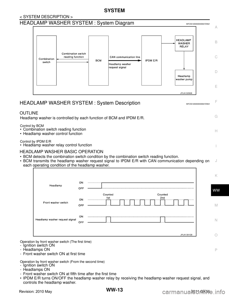
HEADLAMP WASHER SYSTEM : System DiagramINFOID:0000000006372942
HEADLAMP WASHER SYSTEM : System DescriptionINFOID:0000000006372943
OUTLINE
Headlamp washer is controlled by each function of BCM and IPDM E/R.
Control by BCM Combination switch reading function
Headlamp washer control function
Control by IPDM E/R Headlamp washer relay control function
HEADLAMP WASHER BASIC OPERATION
BCM detects the combination switch conditi on by the combination switch reading function.
BCM transmits the headlamp washer request signal to IPDM E/R with CAN communication depending on
each operating condition of the headlamp washer.
Operation by front washer switch (The first time)
- Ignition switch ON
- Headlamps ON
- Front washer switch ON at first time
Operation by front washer switch (From the second time)- Ignition switch ON
- Headlamps ON
- Front washer switch ON at fifth time after the first time
IPDM E/R turns ON/OFF the headlamp washer relay by receiving the headlamp washer request signal, and
controls the headlamp washer.
JPLIA1329GB
JPLIA1391GB
Revision: 2010 May2011 QX56
Page 5543 of 5598
WW-24
< WIRING DIAGRAM >
WIPER AND WASHER SYSTEM
WIRING DIAGRAM
WIPER AND WASHER SYSTEM
Wiring DiagramINFOID:0000000006300465
JCLWM5491GB
Revision: 2010 May2011 QX56