Page 5056 of 5598
ELECTRONICALLY CONTROLLED POWER STEERING SYSTEMSTC-11
< WIRING DIAGRAM >
C
DE
F
H I
J
K L
M A
B
STC
N
O P
JCGWM0393GB
Revision: 2010 May2011 QX56
Page 5057 of 5598
STC-12
< WIRING DIAGRAM >
ELECTRONICALLY CONTROLLED POWER STEERING SYSTEM
JCGWM0394GB
Revision: 2010 May2011 QX56
Page 5059 of 5598

STC-14
< DTC/CIRCUIT DIAGNOSIS >
POWER SUPPLY AND GROUND CIRCUIT
DTC/CIRCUIT DIAGNOSIS
POWER SUPPLY AND GROUND CIRCUIT
Diagnosis ProcedureINFOID:0000000006256125
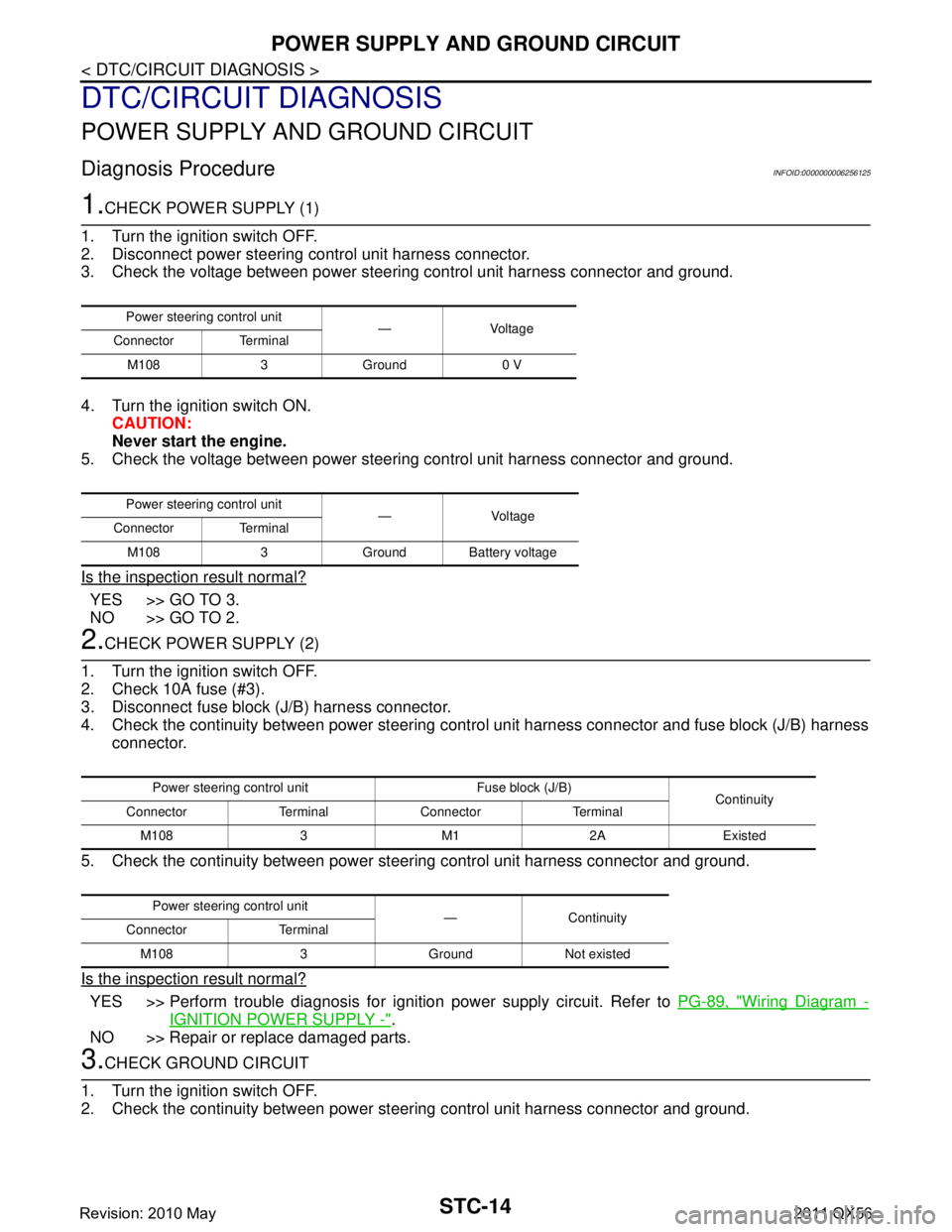
1.CHECK POWER SUPPLY (1)
1. Turn the ignition switch OFF.
2. Disconnect power steering control unit harness connector.
3. Check the voltage between power steering control unit harness connector and ground.
4. Turn the ignition switch ON. CAUTION:
Never start the engine.
5. Check the voltage between power steering control unit harness connector and ground.
Is the inspection result normal?
YES >> GO TO 3.
NO >> GO TO 2.
2.CHECK POWER SUPPLY (2)
1. Turn the ignition switch OFF.
2. Check 10A fuse (#3).
3. Disconnect fuse block (J/B) harness connector.
4. Check the continuity between power steering cont rol unit harness connector and fuse block (J/B) harness
connector.
5. Check the continuity between power st eering control unit harness connector and ground.
Is the inspection result normal?
YES >> Perform trouble diagnosis for ignition power supply circuit. Refer to PG-89, "Wiring Diagram -
IGNITION POWER SUPPLY -".
NO >> Repair or replace damaged parts.
3.CHECK GROUND CIRCUIT
1. Turn the ignition switch OFF.
2. Check the continuity between power st eering control unit harness connector and ground.
Power steering control unit
—Voltage
Connector Terminal
M108 3 Ground 0 V
Power steering control unit — Voltage
Connector Terminal
M108 3 Ground Battery voltage
Power steering control unit Fuse block (J/B) Continuity
Connector Terminal Connector Terminal
M108 3 M1 2A Existed
Power steering control unit —Continuity
Connector Terminal
M108 3 Ground Not existed
Revision: 2010 May2011 QX56
Page 5069 of 5598

STR-1
ENGINE
C
DE
F
G H
I
J
K L
M
SECTION STR
A
STR
N
O P
CONTENTS
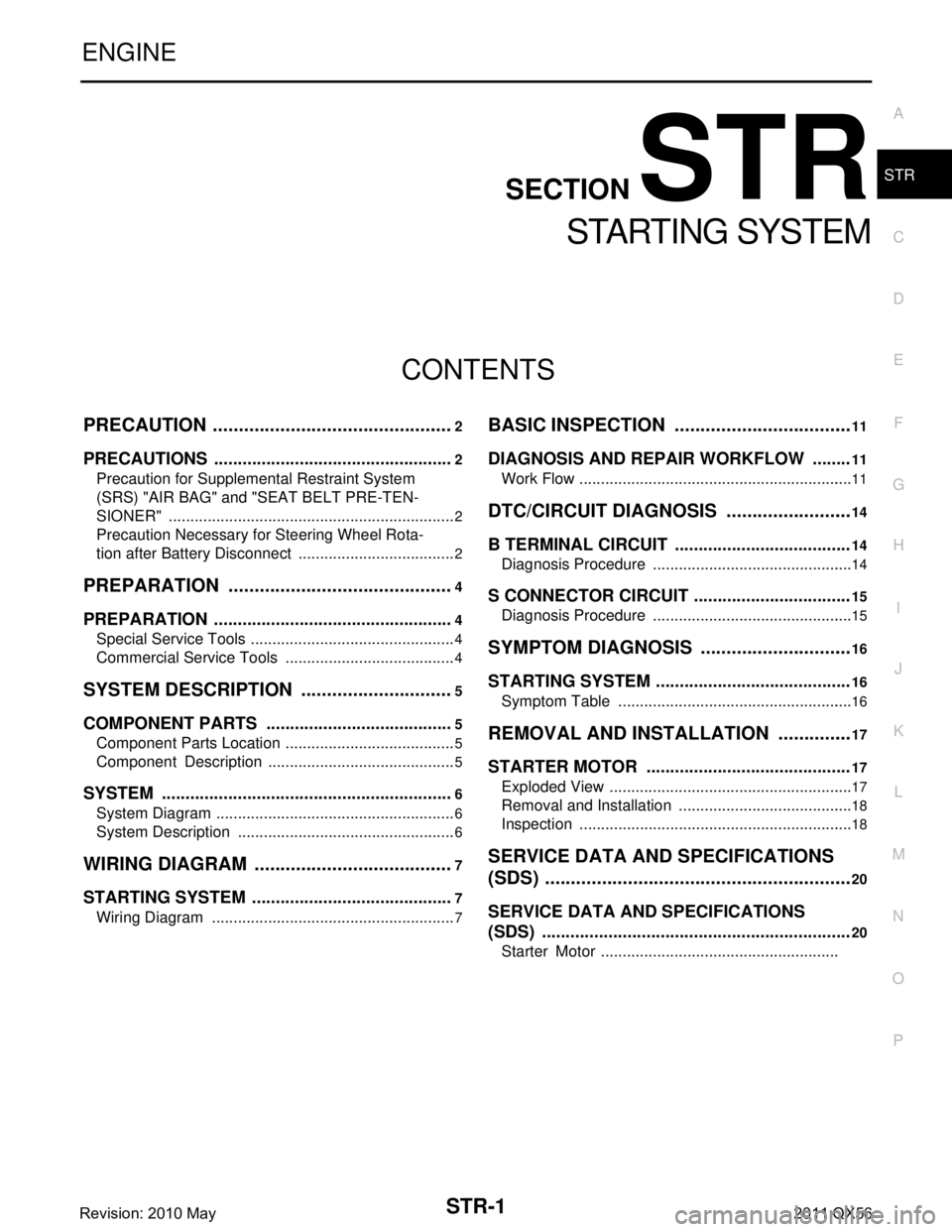
STARTING SYSTEM
PRECAUTION ................ ...............................2
PRECAUTIONS .............................................. .....2
Precaution for Supplemental Restraint System
(SRS) "AIR BAG" and "SEAT BELT PRE-TEN-
SIONER" ............................................................. ......
2
Precaution Necessary for Steering Wheel Rota-
tion after Battery Disconnect .....................................
2
PREPARATION ............................................4
PREPARATION .............................................. .....4
Special Service Tools .......................................... ......4
Commercial Service Tools ........................................4
SYSTEM DESCRIPTION ..............................5
COMPONENT PARTS ................................... .....5
Component Parts Location .................................. ......5
Component Description ............................................5
SYSTEM ..............................................................6
System Diagram .................................................. ......6
System Description ...................................................6
WIRING DIAGRAM .......................................7
STARTING SYSTEM ...................................... .....7
Wiring Diagram ................................................... ......7
BASIC INSPECTION ...................................11
DIAGNOSIS AND REPAIR WORKFLOW ........11
Work Flow ............................................................ ....11
DTC/CIRCUIT DIAGNOSIS .........................14
B TERMINAL CIRCUIT .....................................14
Diagnosis Procedure ........................................... ....14
S CONNECTOR CIRCUIT .................................15
Diagnosis Procedure ...............................................15
SYMPTOM DIAGNOSIS ..............................16
STARTING SYSTEM .........................................16
Symptom Table ................................................... ....16
REMOVAL AND INSTALLATION ...............17
STARTER MOTOR ...........................................17
Exploded View ..................................................... ....17
Removal and Installation .........................................18
Inspection ................................................................18
SERVICE DATA AND SPECIFICATIONS
(SDS) ............... .............................................
20
SERVICE DATA AND SPECIFICATIONS
(SDS) .................................................................
20
Starter Motor .......................................................
Revision: 2010 May2011 QX56
Page 5074 of 5598
STR-6
< SYSTEM DESCRIPTION >
SYSTEM
SYSTEM
System DiagramINFOID:0000000006275520
System DescriptionINFOID:0000000006275521
When selector lever is P or N, power is supplied to starter relay and starter control relay by TCM. And BCM
and IPDM E/R (CPU) detect selector lever P/N condition by the inputted signal.
When starter operating condition is satisfied, IPDM E/R tu rns starter control relay ON by starter control relay
control signal.
When engine cranking condition is satisfied, BCM turns starter relay ON by starter relay control signal.
Then battery power is supplied to starter motor (“S” terminal) through starter control relay and starter relay. And IPDM E/R (CPU) detect starter re lay condition by the inputted signal.
JMBIA2983GB
Revision: 2010 May2011 QX56
Page 5075 of 5598
STARTING SYSTEMSTR-7
< WIRING DIAGRAM >
C
DE
F
G H
I
J
K L
M A
STR
NP
O
WIRING DIAGRAM
STARTING SYSTEM
Wiring DiagramINFOID:0000000006275522
JCBWM2110GB
Revision: 2010 May2011 QX56
Page 5076 of 5598
STR-8
< WIRING DIAGRAM >
STARTING SYSTEM
J C B W M 2 111 G B
Revision: 2010 May2011 QX56
Page 5077 of 5598
STARTING SYSTEMSTR-9
< WIRING DIAGRAM >
C
DE
F
G H
I
J
K L
M A
STR
NP
O
JCBWM2112GB
Revision: 2010 May2011 QX56