Page 4827 of 5598
SRC-34
< WIRING DIAGRAM >
SRS AIR BAG SYSTEM
JCHWM0733GB
Revision: 2010 May2011 QX56
Page 4828 of 5598
SRS AIR BAG SYSTEMSRC-35
< WIRING DIAGRAM >
C
DE
F
G
I
J
K L
M A
B
SRC
N
O P
JCHWM0734GB
Revision: 2010 May2011 QX56
Page 4988 of 5598

ST-1
STEERING
C
DE
F
H I
J
K L
M
SECTION ST
A
B
ST
N
O P
CONTENTS
STEERING SYSTEM
PRECAUTION ................ ...............................3
PRECAUTIONS .............................................. .....3
Precaution for Supplemental Restraint System
(SRS) "AIR BAG" and "SEAT BELT PRE-TEN-
SIONER" ............................................................. ......
3
Precaution Necessary for Steering Wheel Rota-
tion after Battery Disconnect .....................................
3
Service Notice or Precautions for Steering System
......
4
PREPARATION ............................................5
PREPARATION .............................................. .....5
Special Service Tools .......................................... ......5
Commercial Service Tools ........................................6
SYSTEM DESCRIPTION ..............................7
COMPONENT PARTS ................................... .....7
Component Parts Location (Heated Steering
Wheel) ................................................................. ......
7
Component Description (Heated Steering Wheel) ......7
Heated Steering Wheel .............................................7
Heated Steering Wheel Switch .................................8
Heated Steering Wheel Relay ...................................8
SYSTEM ..............................................................9
System Description (Heated Steering Wheel) ..... ......9
WIRING DIAGRAM ......................................10
HEATED STEERING WHEEL ........................ ....10
Wiring Diagram ................................................... ....10
BASIC INSPECTION ...................................13
DIAGNOSIS AND REPAIR WORK FLOW .... ....13
WorkFlow (Heated Steering Wheel) .................... ....13
STEERING WHEEL ............................................14
Inspection ............................................................ ....14
DTC/CIRCUIT DIAGNOSIS .........................16
HEATED STEERING WHEEL SYSTEM ...........16
Component Function Check ................................ ....16
Diagnosis Procedure ...............................................16
Component Inspection (Heated Steering Wheel) ....18
Component Inspection (Heated Steering Wheel
Relay) ......................................................................
19
HEATED STEERING WHEEL SWITCH INDI-
CATOR LAMP ...................................................
20
Component Function Check ....................................20
Diagnosis Procedure ...............................................20
Component Inspection (Heated Steering Wheel
Relay) ......................................................................
22
SYMPTOM DIAGNOSIS ..............................23
HEATED STEERING WHEEL SYSTEM DOES
NOT ACTIVATE ................................................
23
Description ........................................................... ....23
Diagnosis Procedure ...............................................23
HEATED STEERING WHEEL SWITCH INDI-
CATOR LAMP DOES NOT TURN ON ..............
26
Description ...............................................................26
Diagnosis Procedure ...............................................26
NOISE, VIBRATION AND HARSHNESS
(NVH) TROUBLESHOOTING ...........................
29
NVH Troubleshooting Chart ....................................29
PERIODIC MAINTENANCE ........................30
POWER STEERING FLUID ..............................30
Inspection ............................................................ ....30
STEERING WHEEL ..........................................32
Inspection ................................................................32
REMOVAL AND INSTALLATION ...............33
Revision: 2010 May2011 QX56
Page 4996 of 5598

SYSTEMST-9
< SYSTEM DESCRIPTION >
C
DE
F
H I
J
K L
M A
B
ST
N
O P
SYSTEM
System Description (Heated Steering Wheel)INFOID:0000000006225581
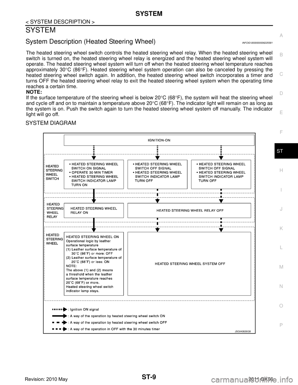
The heated steering wheel switch controls the heated steering wheel relay. When the heated steering wheel
switch is turned on, the heated steering wheel relay is energized and the heated steering wheel system will
operate. The heated steering wheel system will turn of f when the heated steering wheel temperature reaches
approximately 30 °C (86 °F). Heated steering wheel system operati on can also be canceled by pressing the
heated steering wheel switch again. In addition, the heat ed steering wheel switch incorporates a timer and
turns OFF the heated steering wheel relay to exit the heated steering wheel system when the operating time
reaches a certain time.
NOTE:
If the surface temperature of the steering wheel is below 20 °C (68 °F), the system will heat the steering wheel
and cycle off and on to maintain a temperature above 20 °C (68 °F). The indicator light will remain on as long as
the system is on. Push the switch again to turn t he heated steering wheel system off manually. The indicator
light will go off.
SYSTEM DIAGRAM
JSGIA0826GB
Revision: 2010 May2011 QX56
Page 4997 of 5598
ST-10
< WIRING DIAGRAM >
HEATED STEERING WHEEL
WIRING DIAGRAM
HEATED STEERING WHEEL
Wiring DiagramINFOID:0000000006225582
JCGWM0373GB
Revision: 2010 May2011 QX56
Page 4998 of 5598
HEATED STEERING WHEELST-11
< WIRING DIAGRAM >
C
DE
F
H I
J
K L
M A
B
ST
N
O P
JCGWM0390GB
Revision: 2010 May2011 QX56
Page 4999 of 5598
ST-12
< WIRING DIAGRAM >
HEATED STEERING WHEEL
JCGWM0391GB
Revision: 2010 May2011 QX56
Page 5004 of 5598

HEATED STEERING WHEEL SYSTEMST-17
< DTC/CIRCUIT DIAGNOSIS >
C
DE
F
H I
J
K L
M A
B
ST
N
O P
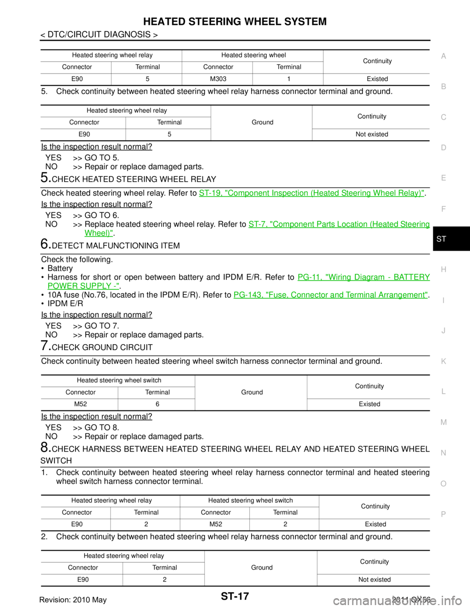
5. Check continuity between heated steering w heel relay harness connector terminal and ground.
Is the inspection result normal?
YES >> GO TO 5.
NO >> Repair or replace damaged parts.
5.CHECK HEATED STEERING WHEEL RELAY
Check heated steering wheel relay. Refer to ST-19, "
Component Inspection (Heated Steering Wheel Relay)".
Is the inspection result normal?
YES >> GO TO 6.
NO >> Replace heated steering wheel relay. Refer to ST-7, "
Component Parts Location (Heated Steering
Wheel)".
6.DETECT MALFUNCTIONING ITEM
Check the following.
Battery
Harness for short or open between bat tery and IPDM E/R. Refer to PG-11, "
Wiring Diagram - BATTERY
POWER SUPPLY -".
10A fuse (No.76, located in the IPDM E/R). Refer to PG-143, "
Fuse, Connector and Terminal Arrangement".
IPDM E/R
Is the inspection result normal?
YES >> GO TO 7.
NO >> Repair or replace damaged parts.
7.CHECK GROUND CIRCUIT
Check continuity between heated steering wheel switch harness connector terminal and ground.
Is the inspection result normal?
YES >> GO TO 8.
NO >> Repair or replace damaged parts.
8.CHECK HARNESS BETWEEN HEATED STEERING WHEEL RELAY AND HEATED STEERING WHEEL
SWITCH 1. Check continuity between heated steering wheel relay harness connector terminal and heated steering
wheel switch harness connector terminal.
2. Check continuity between heated steering w heel relay harness connector terminal and ground.
Heated steering wheel relay Heated steering wheel
Continuity
Connector Terminal Connector Terminal
E90 5 M303 1 Existed
Heated steering wheel relay GroundContinuity
Connector Terminal
E90 5 Not existed
Heated steering wheel switch GroundContinuity
Connector Terminal
M52 6 Existed
Heated steering wheel relay Heated steering wheel switch Continuity
Connector Terminal Connector Terminal
E90 2 M52 2 Existed
Heated steering wheel relay GroundContinuity
Connector Terminal
E90 2 Not existed
Revision: 2010 May2011 QX56