2011 INFINITI QX56 engine
[x] Cancel search: enginePage 2665 of 5598

ENGINE STAND SETTINGEM-103
< UNIT DISASSEMBLY AND ASSEMBLY >
C
DE
F
G H
I
J
K L
M A
EM
NP
O
UNIT DISASSEMBLY AND ASSEMBLY
ENGINE STAND SETTING
SettingINFOID:0000000006289579
NOTE:
Explained here is how to disassemble with engine stand s
upporting transmission surface. When using a differ-
ent type of engine stand, note the difference in the steps, etc.
1. Remove the engine assembly from the vehicle. Refer to EM-98, "
Exploded View".
2. Remove crankshaft pulley. Refer to EM-96, "
FRONT OIL SEAL : Removal and Installation".
NOTE:
The drive plate is fixed with a ring gear stopper [SST: KV10119200 (J-49277)]. Loosen the crankshaft pul-
ley mounting bolts before installing the engine stand.
3. Remove the parts that may restrict installation of engine to a widely used engine stand. Fix crankshaft with a ring gear stopper [SST: KV10119200 (J-49277)]. Loosen drive plate mounting bolt
with power tool.
Check for deformation or damage of drive plate. Refer to EM-115, "
Inspection".
NOTE:
The procedure is described assuming that you us e a widely used engine stand holding the surface, to
which transmission is installed.
4. Remove pilot converter using the pilot bushing puller (commercial service tool), if necessary.
5. Lift the engine with hoist to inst all it onto the widely used engine stand.
CAUTION:
Use an engine stand that has a load capacity [240 kg (529 lb) or more] large enough for supporting
the engine weight.
If the load capacity of the stand is not adequate, remove the following parts beforehand to reduce the potential risk of overturning the stand.
- Remove intake manifold. Refer to EM-30, "
Exploded View".
- Remove fuel injector and fuel tube assembly. Refer to EM-48, "
Exploded View".
- Remove ignition coil. Refer to EM-29, "
Exploded View".
- Remove rocker cover. Refer to EM-33, "
Exploded View".
- Remove exhaust manifold. Refer to EM-40, "
Exploded View".
- Other removable brackets. NOTE:
The figure shows an example of widely used engine stand (A)
that can hold mating surface of transmission with drive plate
removed.
CAUTION:
Before removing the hang ing chains, check the engine
stand is stable and there is no risk of overturning.
6. Drain engine oil. Refer to LU-8, "
Draining".
JPBIA0190ZZ
Revision: 2010 May2011 QX56
Page 2666 of 5598
EM-104
< UNIT DISASSEMBLY AND ASSEMBLY >
ENGINE STAND SETTING
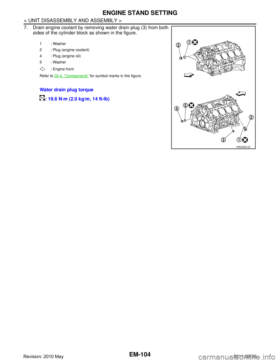
7. Drain engine coolant by removing water drain plug (3) from bothsides of the cylinder block as shown in the figure.
1: Washer
2 : Plug (engine coolant)
4 : Plug (engine oil)
5: Washer
: Engine front
Refer to GI-4, "
Components" for symbol marks in the figure.
Water drain plug torque
: 19.6 N·m (2.0 kg/m, 14 ft-lb)
JPBIA3501ZZ
Revision: 2010 May2011 QX56
Page 2667 of 5598
ENGINE UNITEM-105
< UNIT DISASSEMBLY AND ASSEMBLY >
C
DE
F
G H
I
J
K L
M A
EM
NP
O
ENGINE UNIT
DisassemblyINFOID:0000000006289580
1. Remove intake manifold. Refer to
EM-30, "Exploded View".
2. Remove exhaust manifold. Refer to EM-40, "
Exploded View".
3. Remove oil pan (lower). Refer to EM-54, "
Exploded View".
4. Remove ignition coil and spark plug. Refer to EM-23, "
Exploded View".
5. Remove rocker cover. Refer to EM-33, "
Exploded View".
6. Remove timing chain. Refer to EM-61, "
Exploded View".
7. Remove exhaust camshaft and VVEL ladder assembly. Refer to EM-74, "
Exploded View".
8. Remove cylinder head. Refer to EM-86, "
Exploded View".
AssemblyINFOID:0000000006289581
Assemble in the reverse order of disassembly.
Revision: 2010 May2011 QX56
Page 2671 of 5598
CYLINDER BLOCKEM-109
< UNIT DISASSEMBLY AND ASSEMBLY >
C
DE
F
G H
I
J
K L
M A
EM
NP
O
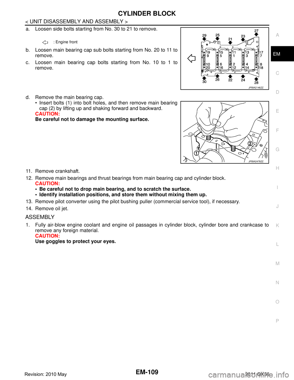
a. Loosen side bolts starting from No. 30 to 21 to remove.
b. Loosen main bearing cap sub bolts starting from No. 20 to 11 to
remove.
c. Loosen main bearing cap bolts starting from No. 10 to 1 to remove.
d. Remove the main bearing cap. Insert bolts (1) into bolt holes, and then remove main bearing
cap (2) by lifting up and shaking forward and backward.
CAUTION:
Be careful not to damage the mounting surface.
11. Remove crankshaft.
12. Remove main bearings and thrust bearings from main bearing cap and cylinder block. CAUTION:
Be careful not to drop main bear ing, and to scratch the surface.
Identify installation positions, and store them without mixing them up.
13. Remove pilot converter using the pilot bushing puller (commercial service tool), if necessary.
14. Remove oil jet.
ASSEMBLY
1. Fully air-blow engine coolant and engine oil passages in cylinder block, cylinder bore and crankcase to remove any foreign material.
CAUTION:
Use goggles to protect your eyes.
: Engine front
JPBIA2146ZZ
JPBIA2478ZZ
Revision: 2010 May2011 QX56
Page 2672 of 5598
EM-110
< UNIT DISASSEMBLY AND ASSEMBLY >
CYLINDER BLOCK
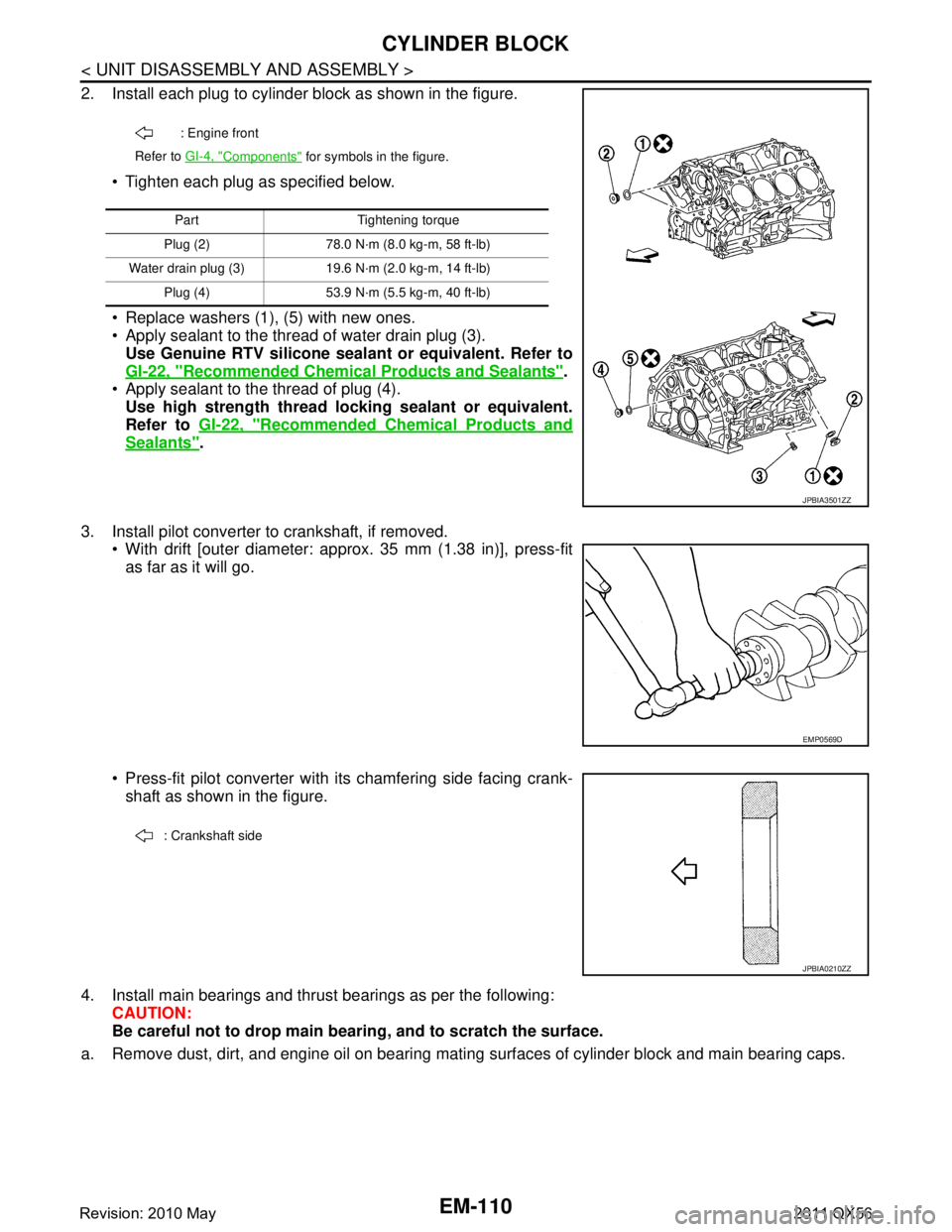
2. Install each plug to cylinder block as shown in the figure. Tighten each plug as specified below.
Replace washers (1), (5) with new ones.
Apply sealant to the thread of water drain plug (3).Use Genuine RTV silicone seal ant or equivalent. Refer to
GI-22, "
Recommended Chemical Pr oducts and Sealants".
Apply sealant to the thread of plug (4). Use high strength thread lo cking sealant or equivalent.
Refer to GI-22, "
Recommended Chemical Products and
Sealants".
3. Install pilot converter to crankshaft, if removed. With drift [outer diameter: appr ox. 35 mm (1.38 in)], press-fit
as far as it will go.
Press-fit pilot converter with its chamfering side facing crank- shaft as shown in the figure.
4. Install main bearings and thrust bearings as per the following: CAUTION:
Be careful not to drop main b earing, and to scratch the surface.
a. Remove dust, dirt, and engine oil on bearing mating surfaces of cylinder block and main bearing caps.
: Engine front
Refer to GI-4, "
Components" for symbols in the figure.
Part Tightening torque
Plug (2) 78.0 N·m (8.0 kg-m, 58 ft-lb)
Water drain plug (3) 19.6 N·m (2.0 kg-m, 14 ft-lb) Plug (4) 53.9 N·m (5.5 kg-m, 40 ft-lb)
JPBIA3501ZZ
EMP0569D
: Crankshaft side
JPBIA0210ZZ
Revision: 2010 May2011 QX56
Page 2673 of 5598
CYLINDER BLOCKEM-111
< UNIT DISASSEMBLY AND ASSEMBLY >
C
DE
F
G H
I
J
K L
M A
EM
NP
O
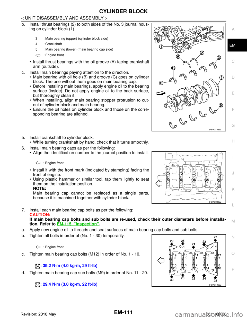
b. Install thrust bearings (2) to both sides of the No. 3 journal hous-
ing on cylinder block (1).
Install thrust bearings with the oil groove (A) facing crankshaftarm (outside).
c. Install main bearings paying attention to the direction. Main bearing with oil hole (B) and groove (C) goes on cylinderblock. The one without them goes on main bearing cap.
Before installing main bearings, apply engine oil to the bearing surface (inside). Do not apply engine oil to the back surface,
but thoroughly clean it.
When installing, align main bearing stopper protrusion to cut-
out of cylinder block and main bearing.
Ensure the oil holes on cylinder block and those on the corre-
sponding bearing are aligned.
5. Install crankshaft to cylinder block. While turning crankshaft by hand, check that it turns smoothly.
6. Install main bearing caps as per the following: Align the identification number to the journal position to install.
Install it with the front mark (indicated by stamping) facing thefront of engine.
Using plastic hammer or similar tool, tap them lightly to seat them on the installation position.
NOTE:
Main bearing cap cannot be replaced as a single parts,
because it is machined together with cylinder block.
7. Install each main bearing cap bolts as per the following: CAUTION:
If main bearing cap bolts and sub bolts are re-u sed, check their outer diameters before installa-
tion. Refer to EM-115, "
Inspection".
a. Apply new engine oil to threads and seat surfaces of main bearing cap bolts and sub bolts.
b. Tighten all bolts in order of (No. 1 - 30) temporarily.
c. Tighten main bearing cap bolts (M12) in order of No. 1 - 10.
d. Tighten main bearing cap sub bolts (M9) in order of No. 11 - 20.
3 : Main bearing (uppe r) (cylinder block side)
4 : Crankshaft
5 : Main bearing (lower) (main bearing cap side)
: Engine front
JPBIA2148ZZ
: Engine front
JPBIA2380ZZ
: Engine front
: 39.2 N·m (4.0 kg-m, 29 ft-lb)
: 29.4 N·m (3.0 kg-m, 22 ft-lb)
JPBIA2146ZZ
Revision: 2010 May2011 QX56
Page 2674 of 5598
![INFINITI QX56 2011 Factory Service Manual
EM-112
< UNIT DISASSEMBLY AND ASSEMBLY >
CYLINDER BLOCK
e. Tighten main bearing cap bolts (M12) in order of No. 1 - 10(clockwise).
CAUTION:
Use the angle wrench [SST: KV10112100 (BT8653-A)] (A) to
ch INFINITI QX56 2011 Factory Service Manual
EM-112
< UNIT DISASSEMBLY AND ASSEMBLY >
CYLINDER BLOCK
e. Tighten main bearing cap bolts (M12) in order of No. 1 - 10(clockwise).
CAUTION:
Use the angle wrench [SST: KV10112100 (BT8653-A)] (A) to
ch](/manual-img/42/57033/w960_57033-2673.png)
EM-112
< UNIT DISASSEMBLY AND ASSEMBLY >
CYLINDER BLOCK
e. Tighten main bearing cap bolts (M12) in order of No. 1 - 10(clockwise).
CAUTION:
Use the angle wrench [SST: KV10112100 (BT8653-A)] (A) to
check tightening angl e. Never make judgment by visual
inspection.
f. Tighten main bearing cap sub bolts (M9) in order of No. 11 - 20. (clockwise)
g. Tighten side bolts (M10) in order of No. 21 - 30. After installing bolts, check that crankshaft can be rotated smoothly by hand.
Check the crankshaft end play. Refer to EM-137, "
CylinderBlock".
8. Install rear oil seal retainer. Apply a continuous bead of liquid gasket with tube presser
(commercial service tool) to rear oil seal retainer as shown in
the figure.
Use Genuine RTV silicone seal ant or equivalent. Refer to
GI-22, "
Recommended Chemical Products and Sealants".
9. Install rear oil seal on rear oil seal retainer.
Apply new engine oil to both oil seal lip (A) and dust seal lip(B).
Install it so that each seal lip is oriented as shown in the figure. CAUTION:
Be careful not to scratch or make burrs on circumference
of oil seal.
Press in rear oil seal (1) to the position as shown in the figure.
Using a suitable drift [outer diameter: 101 mm (3.98 in)].
Check the garter spring is in position and seal lips are not inverted.
10. Install piston to connecting rod as per the following: Angle tightening: 40 degrees
Angle tightening: 30 degrees
JPBIA2149ZZ
: 49.0 N·m (5.0 kg-m, 36 ft-lb)
A : Protrusion
b : 4.0 - 5.6 mm (0.157 - 0.220 in)
c:
φ3.4 - 4.4 mm (0.134 - 0.173 in)
JPBIA2102ZZ
: Engine inside
: Engine outside
JPBIA0054ZZ
B : Rear oil seal retainer rear end face
a : 0 - 0.5 mm (0 - 0.020 in)
JPBIA0152ZZ
Revision: 2010 May2011 QX56
Page 2675 of 5598
CYLINDER BLOCKEM-113
< UNIT DISASSEMBLY AND ASSEMBLY >
C
DE
F
G H
I
J
K L
M A
EM
NP
O
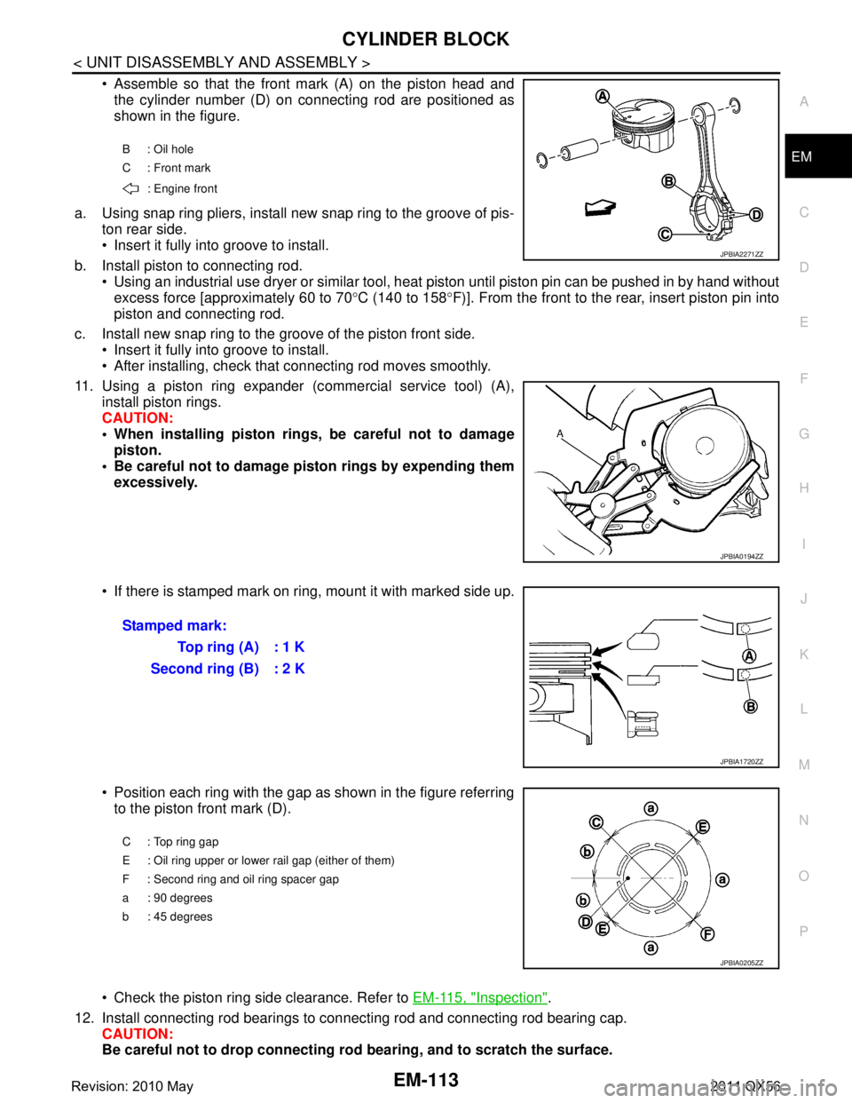
Assemble so that the front mark (A) on the piston head and
the cylinder number (D) on connecting rod are positioned as
shown in the figure.
a. Using snap ring pliers, install new snap ring to the groove of pis- ton rear side.
Insert it fully into groove to install.
b. Install piston to connecting rod. Using an industrial use dryer or similar tool, heat piston until piston pin can be pushed in by hand without
excess force [approximately 60 to 70 °C (140 to 158 °F)]. From the front to the rear, insert piston pin into
piston and connecting rod.
c. Install new snap ring to the groove of the piston front side. Insert it fully into groove to install.
After installing, check that connecting rod moves smoothly.
11. Using a piston ring expander (c ommercial service tool) (A),
install piston rings.
CAUTION:
When installing piston rings, be careful not to damage piston.
Be careful not to damage piston rings by expending them excessively.
If there is stamped mark on ri ng, mount it with marked side up.
Position each ring with the gap as shown in the figure referring to the piston front mark (D).
Check the piston ring side clearance. Refer to EM-115, "
Inspection".
12. Install connecting rod bearings to connecting rod and connecting rod bearing cap. CAUTION:
Be careful not to drop connecting r od bearing, and to scratch the surface.
B : Oil hole
C : Front mark
: Engine front
JPBIA2271ZZ
JPBIA0194ZZ
Stamped mark: To p r i n g ( A ) : 1 K
Second ring (B) : 2 K
JPBIA1720ZZ
C : Top ring gap
E : Oil ring upper or lower rail gap (either of them)
F : Second ring and oil ring spacer gap
a : 90 degrees
b : 45 degrees
JPBIA0205ZZ
Revision: 2010 May2011 QX56