2011 FORD KUGA accessory
[x] Cancel search: accessoryPage 82 of 2057

sometimes noticed in the steering wheel/column,
seats, front floor panel, front door trim panel or
front end sheet metal. It is a low frequency
vibration (around 9-15 cycles per second). It
may or may not be increased by applying the
brakes lightly. REFER to Idle
Boom/Shake/Vibration in the Driveline Noise
and Vibration Symptom Chart.
3. High Speed: A vibration is felt in the front floor panel or seats with no visible shake, but with
an accompanying sound or rumble, buzz, hum,
drone or booming noise. Coast with the clutch
pedal depressed (manual transmission) or shift
control selector lever in "N" (NEUTRAL)
(automatic transmission) and engine idling. If
vibration is still evident, it may be related to
wheels, tires, front brake discs, wheel hubs or
front wheel bearings. REFER to Shake and
Vibration While Driving in the Driveline Noise
and Vibration Symptom Chart.
4. Engine rpm Sensitive: A vibration is felt whenever the engine reaches a particular rpm.
It will disappear in neutral coasts. The vibration
can be duplicated by operating the engine at
the problem rpm while the vehicle is stationary.
It can be caused by any component, from the
accessory drive belt to the clutch or torque
converter which turns at engine speed when the
vehicle is stopped. REFER to Shake and
Vibration While Driving in the Driveline Noise
and Vibration Symptom Chart.
5. Noise and Vibration While Turning: Clicking, popping or grinding noises may be due to the
following:
• worn, damaged or incorrectly installed front wheel bearing.
• damaged powertrain/drivetrain mounts.
Road Conditions
An experienced technician will always establish a
route that will be used for all NVH diagnosis road
tests. The road selected should be reasonably
smooth, level and free of undulations (unless a
particular condition needs to be identified). A
smooth asphalt road that allows driving over a
range of speeds is best. Gravel or bumpy roads
are unsuitable because of the additional road noise
produced. Once the route is established and consistently used, the road noise variable is
eliminated from the test results.
NOTE:
Some concerns may be apparent only on
smooth asphalt roads.
If a customer complains of a noise or vibration on
a particular road and only on a particular road, the
source of the concern may be the road surface. If
possible, try to test the vehicle on the same type
of road.
Vehicle Preparation
Carry out a thorough visual inspection of the
vehicle before carrying out the road test. Note
anything which is unusual. Do not repair or adjust
any condition until the road test is carried out,
unless the vehicle is inoperative or the condition
could pose a hazard to the technician. After
verifying that the condition has been corrected,
make sure all components removed have been
installed.
Power Steering Conditions
Check for the noise in the following conditions to
verify the customer concern.
• Check for the noise in several temperature conditions.
• Is the noise from when the vehicle was new?
• Can the noise be repeated constantly or is it random?
• Check the condition of the vehicle age, mileage and service record.
• Interview the customer to find the operating condition in which the noise will occur. Test the
vehicle based on the detail(s) from the customer
interview.
• Follow the power steering operation noise condition tables below, to find which condition
the noise will occur.
Power Steering Operation Noise Check
Step 1: Check for NVH concerns from non-steering
components, which may sound like noises coming
from the steering system.
G37349en2008.50 Kuga8/2011
100-04- 4
Noise, Vibration and Harshness
100-04- 4
DIAGNOSIS AND TESTING
TO MODEL INDEX
BACK TO CHAPTER INDEX
FORD KUGA 2011.0MY WORKSHOP REPAIR MANUAL
Page 93 of 2057

PINPOINT TEST B : TIP-IN MOAN
DETAILS/RESULTS/ACTIONS
TEST CONDITIONS
B1: CHECK THE AIR CLEANER
1 Check the condition of the air cleaner mounts,
inlet tube, outlet tube, resonators and all other
components associated with the air induction
system for correct installation and tightness of
all connections.
• Are the components OK?
zYe s GO to B2.
zNoREPAIR or INSTALL new components as
necessary. ROAD TEST as necessary.
B2: CHECK THE EXHAUST SYSTEM
1 Carry out the exhaust system neutralizing
procedure.
• Is the exhaust system OK?
zYe s GO to B3.
zNoREPAIR as necessary. ROAD TEST as
necessary.
B3: CHECK THE POWER STEERING
1 Remove the accessory drive belt and test for
tip-in moan. REFER to:
Accessory Drive Belt (303-05 Accessory Drive
- 2.5L Duratec (147kW/200PS) - VI5, Removal
and Installation),
• Is the tip-in moan OK?
zYe s REPAIR the power steering as necessary.
REFER to: Steering System (211-00 Steering
System - General Information, Diagnosis
and Testing).
zNo
GO to B4.
G37349en2008.50 Kuga8/2011
100-04- 15
Noise, Vibration and Harshness
100-04- 15
DIAGNOSIS AND TESTING
TO MODEL INDEX
BACK TO CHAPTER INDEX
FORD KUGA 2011.0MY WORKSHOP REPAIR MANUAL
Page 183 of 2057

Instrument Cluster and Panel Illumination
Refer to
Wiring Diagrams Section 413-00, for
schematic and connector information.
Principles of Operation
NOTE: A new instrument cluster must be
configured.
The instrument cluster and panel illumination
consists of dimmable and non-dimmable
illumination. The dimmable panel illumination is
controlled by the panel illumination switch (part of
the headlamp switch), which allows the brightness
level of the backlights to be adjusted dependent
on the customer preference. When the headlamp
switch is in the parking lamps ON or headlamps
ON position, the intensity of the backlighting can
be adjusted using the panel dimmer switch. The
non dimmable illumination allows for full intensity
dependant on the ignition switch position.
Instrument Cluster and Dimmable
Backlighting A.
Tachometer
B. Engine coolant temperature gauge
C. Fuel gauge
D. Speedometer
E. Information display
The dimmable illumination utilizes light emitting
diodes (LEDs) and bulb(s). The following dimmable
components are backlight using LEDs only:
• ashtray
• cigar lighter
• transmission control lever
• heater control panel
• audio unit • navigation system display module
• instrument cluster
• climate control module
• hazard switch
• traction control system disable switch
• right-hand and left-hand heated front seat
switch(es)
Inspection and Verification
1. Verify the customer concern.
2. Visually inspect for obvious signs of mechanical
or electrical damage.
Visual Inspection Chart Electrical
Mechanical
– Fuse(s)
– Loose or corrodedconnector(s)
– Instrument cluster
– Wiring Harness
– Circuit
– LED(s)
– Bulb(s)
– Engine/engine
compartment or
underbody compon-
ents
– Fluid levels
– Accessory installa- tion
3. If an obvious cause for an observed or reported concern is found, correct the cause (if possible)
before proceeding to the next step.
4. If the cause is not visually evident, verify the symptom and refer to the diagnostic tab within
the Ford approved diagnostic tool. G1054961en
2008.50 Kuga 8/2011 413-00-2
Instrument Cluster and Panel Illumination
413-00-2
DIAGNOSIS AND TESTINGTO MODEL INDEX
BACK TO CHAPTER INDEX
FORD KUGA 2011.0MY WORKSHOP REPAIR MANUALE98738ABCED
Page 263 of 2057
Charging System
Refer to Wiring Diagrams Section 414-02, for
schematic and connector information.
General Equipment
Midtronics EXP-1050 battery tester
Midtronics GR590-2
Ford diagnostic equipment
Inspection and Verification
WARNINGS: Batteries contain sulphuric acid. Avoid
contact with skin, eyes, or clothing. Also,
shield your eyes when working near
batteries to protect against possible
splashing of the acid solution. In case of
acid contact with skin or eyes, flush
immediately with water for a minimum of
15 minutes and get prompt medical
attention. If acid is swallowed, call a
physician immediately. Failure to follow
these instructions may result in personal
injury.
Batteries normally produce explosive
gases which can cause personal injury.
Therefore, do not allow flames, sparks or
lighted substances to come near the
battery. When charging or working near a
battery, always shield your face and
protect your eyes. Always provide
ventilation. Failure to follow these
instructions may result in personal injury.
1. Verify the customer concern.
2. Visually inspect for obvious signs of mechanical
or electrical damage.
Visual Inspection Chart Electrical
Mechanical
– Fuse(s)
– Wiring harness(es)
– Generator
– Electricalconnector(s)
– Battery junction box (BJB)
– Battery
– Battery cables
– Battery monitoring sensor (BMS)
– Charging system warning indicator
–
Accessory drive belt
– Generator
3. If an obvious cause for an observed or reported concern is found, correct the cause (if possible)
before proceeding to the next step.
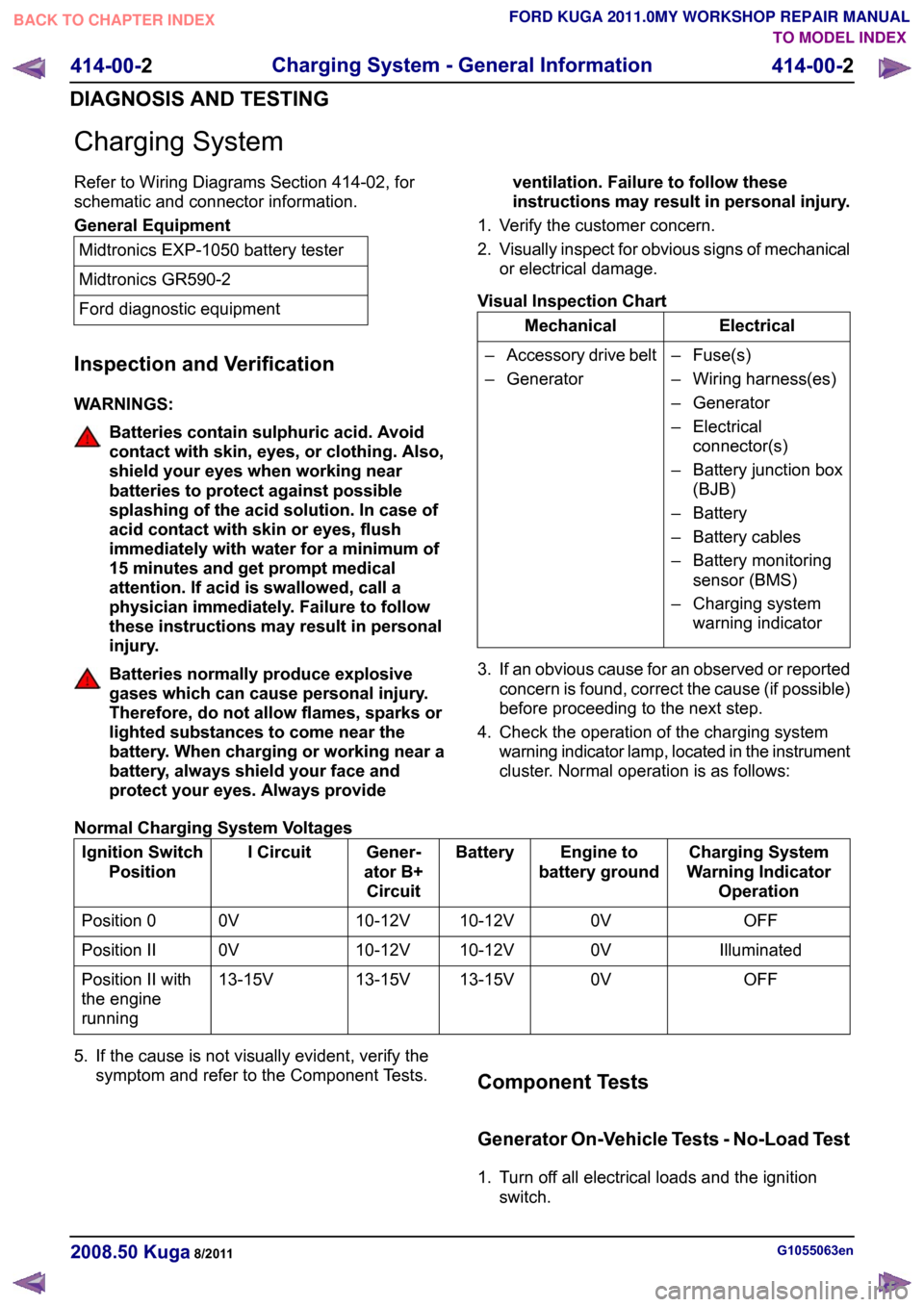
4. Check the operation of the charging system warning indicator lamp, located in the instrument
cluster. Normal operation is as follows:
Normal Charging System Voltages Charging System
Warning Indicator Operation
Engine to
battery ground
Battery
Gener-
ator B+ Circuit
I Circuit
Ignition Switch
Position
OFF
0V
10-12V
10-12V
0V
Position 0
Illuminated
0V
10-12V
10-12V
0V
Position II
OFF
0V
13-15V
13-15V
13-15V
Position II with
the engine
running
5. If the cause is not visually evident, verify the symptom and refer to the Component Tests. Component Tests
Generator On-Vehicle Tests - No-Load Test
1. Turn off all electrical loads and the ignition
switch. G1055063en
2008.50 Kuga 8/2011 414-00-2
Charging System - General Information
414-00-2
DIAGNOSIS AND TESTINGTO MODEL INDEX
BACK TO CHAPTER INDEX
FORD KUGA 2011.0MY WORKSHOP REPAIR MANUAL
Page 1558 of 2057
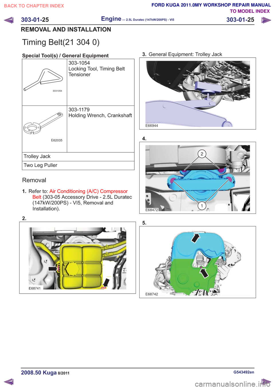
Timing Belt(21 304 0)
Special Tool(s) / General Equipment303-1054
Locking Tool, Timing Belt
Tensioner
3031054
303-1179
Holding Wrench, Crankshaft
E62035
Trolley Jack
Two Leg Puller
Removal
1.Refer to: Air Conditioning (A/C) Compressor
Belt (303-05 Accessory Drive - 2.5L Duratec
(147kW/200PS) - VI5, Removal and
Installation).
2.
E68741
3. General Equipment: Trolley Jack
E66944
4.
E68472
2
1
5.
E68742
G543492en2008.50 Kuga8/2011
303-01- 25
Engine— 2.5L Duratec (147kW/200PS) - VI5303-01-
25
REMOVAL AND INSTALLATION
TO MODEL INDEX
BACK TO CHAPTER INDEX
FORD KUGA 2011.0MY WORKSHOP REPAIR MANUAL
Page 1563 of 2057
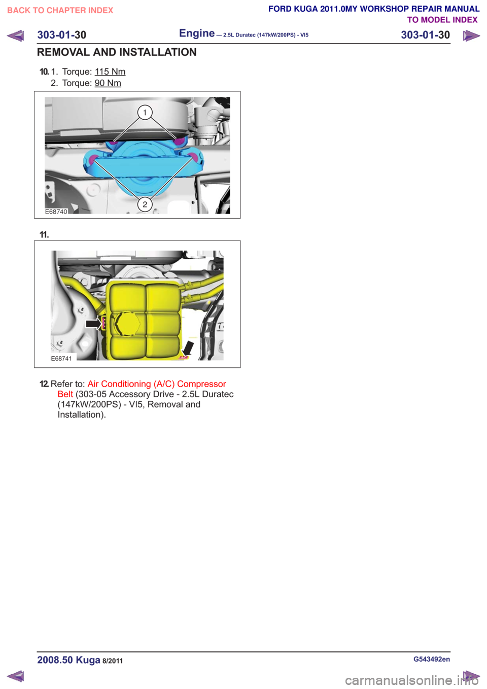
10.Torque: 115Nm1.
2. Torque: 90
Nm
E68740
1
2
11 .
E68741
12.Refer to: Air Conditioning (A/C) Compressor
Belt (303-05 Accessory Drive - 2.5L Duratec
(147kW/200PS) - VI5, Removal and
Installation).
G543492en2008.50 Kuga8/2011
303-01- 30
Engine— 2.5L Duratec (147kW/200PS) - VI5303-01-
30
REMOVAL AND INSTALLATION
TO MODEL INDEX
BACK TO CHAPTER INDEX
FORD KUGA 2011.0MY WORKSHOP REPAIR MANUAL
Page 1577 of 2057
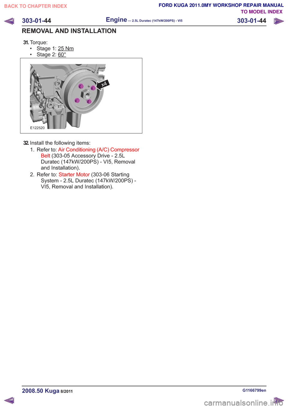
31.Torque:
• Stage 1: 25
Nm
• Stage 2: 60°
E122520
x4
32.Install the following items:
1. Refer to: Air Conditioning (A/C) Compressor
Belt (303-05 Accessory Drive - 2.5L
Duratec (147kW/200PS) - VI5, Removal
and Installation).
2. Refer to: Starter Motor (303-06 Starting
System - 2.5L Duratec (147kW/200PS) -
VI5, Removal and Installation).
G1166799en2008.50 Kuga8/2011
303-01- 44
Engine— 2.5L Duratec (147kW/200PS) - VI5303-01-
44
REMOVAL AND INSTALLATION
TO MODEL INDEX
BACK TO CHAPTER INDEX
FORD KUGA 2011.0MY WORKSHOP REPAIR MANUAL
Page 1578 of 2057
Oil Pan(21 154 0)
General EquipmentCable Ties
Materials
Specification
Name
WSS-M2C913-C
Engine Oil - 5W-30
WSK-M2G348-A7 /
5U7J-M2G348-BA
Flange Sealant - Anaer-
obic LP
Removal
NOTE:
Removal steps in the procedure may
contain installation details.
1. Refer to: Accessory Drive Belt (303-05
Accessory Drive - 2.5L Duratec
(147kW/200PS) - VI5, Removal and
Installation).
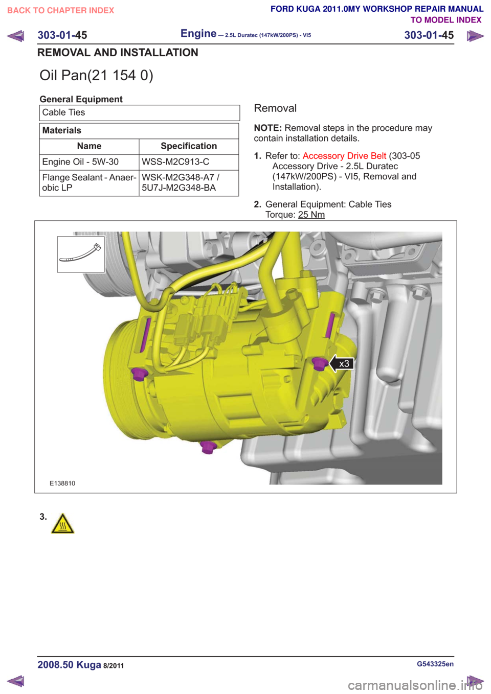
2. General Equipment: Cable Ties
Torque: 25
Nm
E138810
x3
3.
G543325en2008.50 Kuga8/2011
303-01- 45
Engine— 2.5L Duratec (147kW/200PS) - VI5303-01-
45
REMOVAL AND INSTALLATION
TO MODEL INDEX
BACK TO CHAPTER INDEX
FORD KUGA 2011.0MY WORKSHOP REPAIR MANUAL