Page 267 of 2057
Action
Battery Tester Reading WARNING: Do not recharge the battery.
Make sure that the surface charge was removed. A "REPLACE BATTERY" result could also mean
a poor connection between the battery cables and the battery. Check the connections are OK and
retest. If the result remains the same, INSTALL a NEW battery
REFER to: Battery(414-01 Battery, Mounting and
Cables, Removal and Installation).
REPLACE BATTERY or BAD CELL BATTERY
In addition it is advisable to check the vehicle electrical system. Check that the generator is functioning
correctly and the vehicle does not have an excessive key-off load (in general this should be under
20mA after 40 minutes of key off).
Midtronics EXP-1050 Battery Tester Test
Code
At the end of the test, use the arrow keys to scroll
down the screens to see additional information.
One of these is the TEST CODE.
The TEST CODE has 11 digits, for example:
0021U-B88WKX.
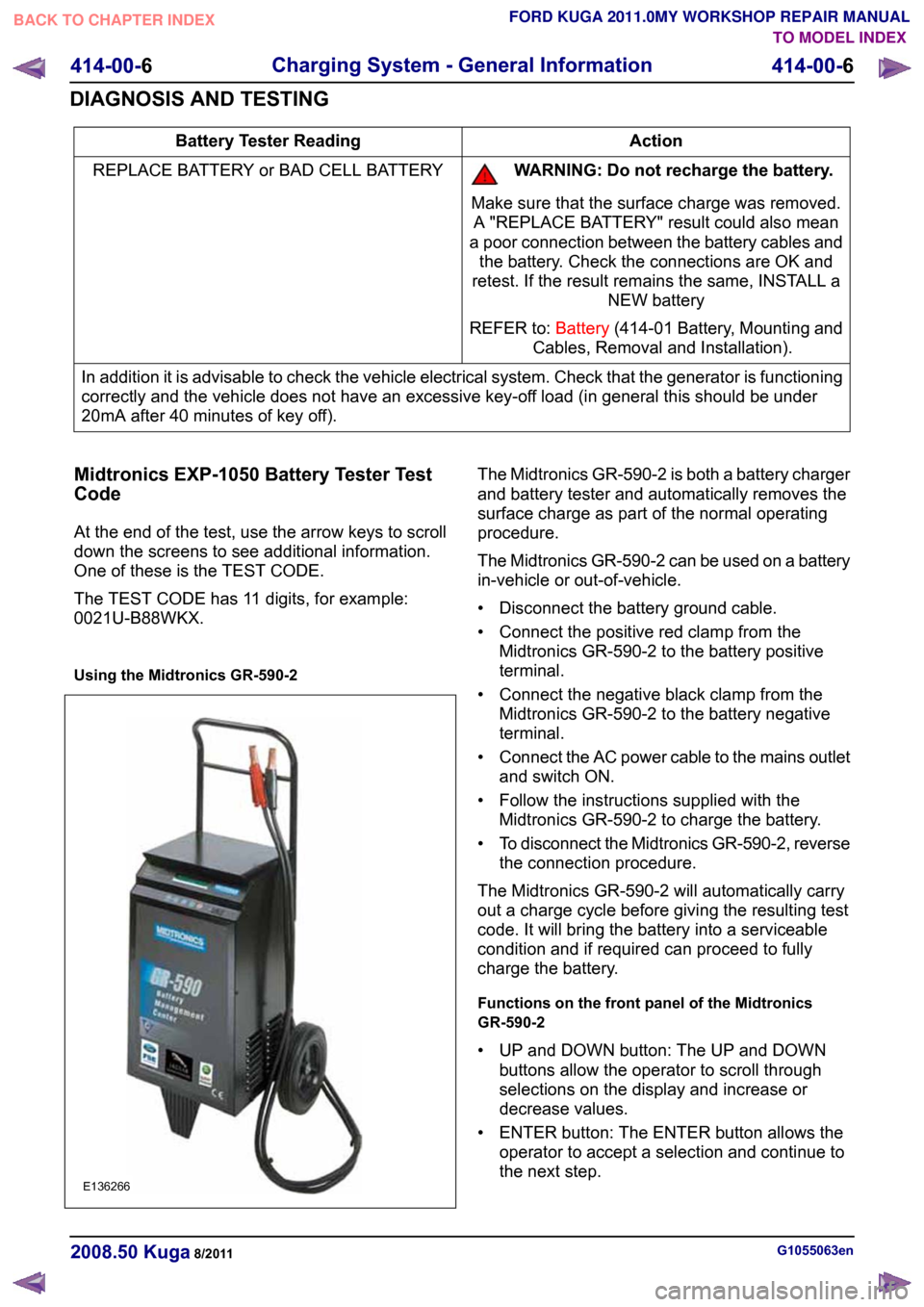
Using the Midtronics GR-590-2 The Midtronics GR-590-2 is both a battery charger
and battery tester and automatically removes the
surface charge as part of the normal operating
procedure.
The Midtronics GR-590-2 can be used on a battery
in-vehicle or out-of-vehicle.
• Disconnect the battery ground cable.
• Connect the positive red clamp from the
Midtronics GR-590-2 to the battery positive
terminal.
• Connect the negative black clamp from the Midtronics GR-590-2 to the battery negative
terminal.
• Connect the AC power cable to the mains outlet
and switch ON.
• Follow the instructions supplied with the Midtronics GR-590-2 to charge the battery.
• To disconnect the Midtronics GR-590-2, reverse
the connection procedure.
The Midtronics GR-590-2 will automatically carry
out a charge cycle before giving the resulting test
code. It will bring the battery into a serviceable
condition and if required can proceed to fully
charge the battery.
Functions on the front panel of the Midtronics
GR-590-2
• UP and DOWN button: The UP and DOWN buttons allow the operator to scroll through
selections on the display and increase or
decrease values.
• ENTER button: The ENTER button allows the operator to accept a selection and continue to
the next step. G1055063en
2008.50 Kuga 8/2011 414-00-6
Charging System - General Information
414-00-6
DIAGNOSIS AND TESTINGTO MODEL INDEX
BACK TO CHAPTER INDEX
FORD KUGA 2011.0MY WORKSHOP REPAIR MANUALE136266
Page 269 of 2057
SECTION 414-01 Battery, Mounting and Cables
VEHICLE APPLICATION:
2008.50 Kuga
PAGE
CONTENTS
GENERAL PROCEDURES
414-01-2
Battery Disconnect and Connect........................................................................................
414-01-2
Disconnect ..........................................................................................................................
414-01-3
Connect ..............................................................................................................................
REMOVAL AND INSTALLATION 414-01-4
Battery ................................................................................................................................ 414-01-1
Battery, Mounting and Cables
414-01-1
.TO MODEL INDEX
BACK TO CHAPTER INDEX
FORD KUGA 2011.0MY WORKSHOP REPAIR MANUAL
Page 270 of 2057

Battery Disconnect and Connect
Disconnect
WARNINGS:
Batteries normally produce explosive
gases which may cause personal injury,
therefore do not allow flames, sparks or
lighted substances to come near the
battery. When charging or working near
the battery always shield your face and
protect your eyes. Always provide
adequate ventilation. Failure to follow
these instructions may result in personal
injury.
The supplemental restraint system (SRS)
is active for a certain length of time after
the power supply has been disconnected.
Wait for a minimum of 3 minutes before
disconnecting or removing any SRS
components.
Audio unit key code saving devices must
not be used when working on
supplemental restraint or fuel systems.
When using these devices the vehicle
electrical system is still live but with a
reduced current flow. Failure to follow this
instruction may result in personal injury.
CAUTION: Make sure the engine is not
running before disconnecting the battery
ground cable to avoid damage to the
vehicle electrical system.
NOTE: Disconnecting the battery will erase fault
codes, drive values and customer data stored in
the modules.
NOTE: This procedure should be used to
disconnect the battery while carrying out repairs
that refer to the battery being disconnected.
1. Refer to: Battery and Battery Charging Health
and Safety Precautions (100-00 General
Information, Description and Operation).
2. Obtain and record the audio unit keycode and
preset radio frequencies. 3.
G1062389en
2008.50 Kuga 8/2011 414-01-2
Battery, Mounting and Cables
414-01-2
GENERAL PROCEDURESTO MODEL INDEX
BACK TO CHAPTER INDEX
FORD KUGA 2011.0MY WORKSHOP REPAIR MANUALE103137
Page 271 of 2057
Connect
1.
Torque: 15 Nm
G1062389en
2008.50 Kuga 8/2011 414-01-3
Battery, Mounting and Cables
414-01-3
GENERAL PROCEDURESTO MODEL INDEX
BACK TO CHAPTER INDEX
FORD KUGA 2011.0MY WORKSHOP REPAIR MANUALE103138
Page 272 of 2057
Battery
Removal
1.
Refer to: Battery and Battery Charging Health
and Safety Precautions (100-00 General
Information, Description and Operation).
2. Refer to: Battery Disconnect and Connect
(414-01 Battery, Mounting and Cables,
General Procedures).
3. Installation
1.
Torque:
• 1 15 Nm
• 2 10 Nm
• 3 12 Nm
2.
Refer to: Battery Disconnect and Connect
(414-01 Battery, Mounting and Cables,
General Procedures). G1065713en
2008.50 Kuga 8/2011 414-01-4
Battery, Mounting and Cables
414-01-4
REMOVAL AND INSTALLATIONTO MODEL INDEX
BACK TO CHAPTER INDEX
FORD KUGA 2011.0MY WORKSHOP REPAIR MANUALE102716123 E102716123
Page 464 of 2057

Generic Electronic Module (GEM)
General Equipment
Ford Diagnostic Equipment
Removal
CAUTIONS: Modules must not be swapped between
vehicles.
Compare the number of relays and fuses
in the defective GEM and the new GEM.
Transfer from the defective GEM any relays
and fuses which are not in the new GEM.
In doing so, pay attention that fuses with
the correct Ampere rating are used, by
referring to the wiring diagrams.
When installing a new GEM on vehicles
with a diesel engine, make sure that a fuel
pump fuse (F111) with 5A is used.
When installing a new GEM on vehicles
with a petrol engine, make sure that a fuel
pump fuse (F111) with 15A is used.
NOTE: GEM is integrated into the central junction
box (CJB) and cannot be removed individually.
1. NOTE: This step is only necessary when
installing a new component.
Upload the GEM configuration information using
the Programmable Modules Installation Routine.
General Equipment: Ford Diagnostic Equipment
2. Refer to: Battery Disconnect and Connect
(414-01 Battery, Mounting and Cables,
General Procedures).
3. 4.
5.
Installation
1.
To install, reverse the removal procedure.
2. NOTE: This step is only necessary when
installing a new component.
Download the GEM configuration information
to the newly installed GEM using the
programmable modules installation routine.
3. NOTE: This step is only necessary when
installing a new component.
Program all keys using the Key Programming
Routine.
General Equipment: Ford Diagnostic Equipment G1065605en
2008.50 Kuga 8/2011 419-10-14
Multifunction Electronic Modules
419-10-14
REMOVAL AND INSTALLATIONTO MODEL INDEX
BACK TO CHAPTER INDEX
FORD KUGA 2011.0MY WORKSHOP REPAIR MANUALE51159 122E102019 E102020
Page 1434 of 2057
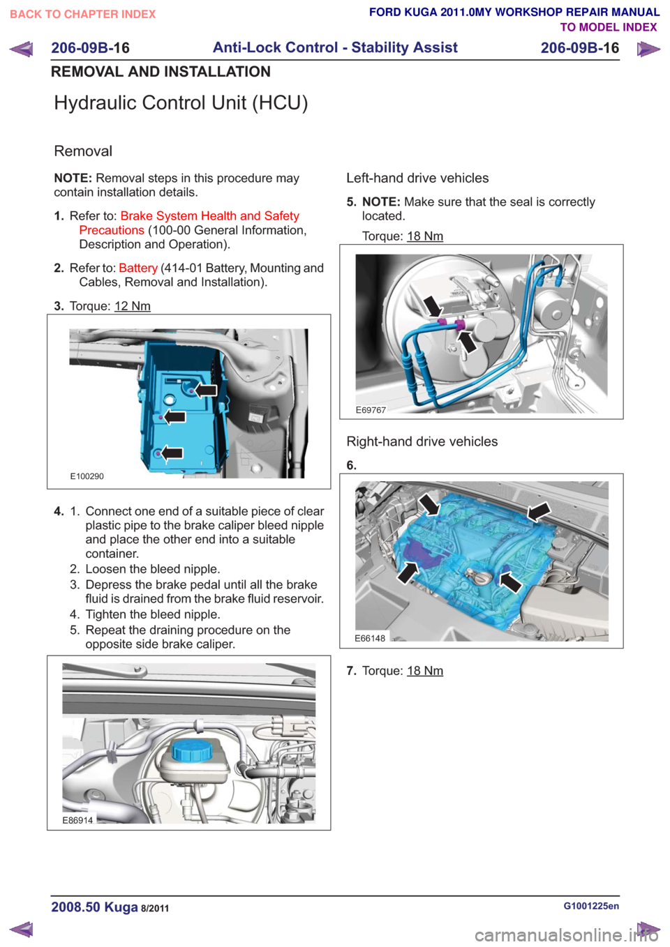
Hydraulic Control Unit (HCU)
Removal
NOTE:Removal steps in this procedure may
contain installation details.
1. Refer to: Brake System Health and Safety
Precautions (100-00 General Information,
Description and Operation).
2. Refer to: Battery(414-01 Battery, Mounting and
Cables, Removal and Installation).
3. Torque: 12
Nm
E100290
4. Connect one end of a suitable piece of clear
plastic pipe to the brake caliper bleed nipple
1.
and place the other end into a suitable
container.
2. Loosen the bleed nipple.
3. Depress the brake pedal until all the brake fluid is drained from the brake fluid reservoir.
4. Tighten the bleed nipple.
5. Repeat the draining procedure on the opposite side brake caliper.
E86914
Left-hand drive vehicles
5. NOTE: Make sure that the seal is correctly
located.
Torque: 18
Nm
E69767
Right-hand drive vehicles
6.
E66148
7. Torque: 18Nm
G1001225en2008.50 Kuga8/2011
206-09B- 16
Anti-Lock Control - Stability Assist
206-09B- 16
REMOVAL AND INSTALLATION
TO MODEL INDEX
BACK TO CHAPTER INDEX
FORD KUGA 2011.0MY WORKSHOP REPAIR MANUAL
Page 1506 of 2057
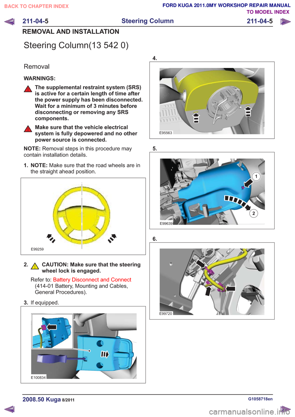
Steering Column(13 542 0)
Removal
WARNINGS:
The supplemental restraint system (SRS)
is active for a certain length of time after
the power supply has been disconnected.
Wait for a minimum of 3 minutes before
disconnecting or removing any SRS
components.
Make sure that the vehicle electrical
system is fully depowered and no other
power source is connected.
NOTE: Removal steps in this procedure may
contain installation details.
1. NOTE: Make sure that the road wheels are in
the straight ahead position.
E99259
2. CAUTION: Make sure that the steering wheel lock is engaged.
Refer to: Battery Disconnect and Connect
(414-01 Battery, Mounting and Cables,
General Procedures).
3. If equipped.
E100834
4.
E95563
5.
E99639
1
2
6.
E99720
G1058718en2008.50 Kuga8/2011
211-04- 5
Steering Column
211-04- 5
REMOVAL AND INSTALLATION
TO MODEL INDEX
BACK TO CHAPTER INDEX
FORD KUGA 2011.0MY WORKSHOP REPAIR MANUAL