2011 FORD KUGA clutch
[x] Cancel search: clutchPage 2010 of 2057
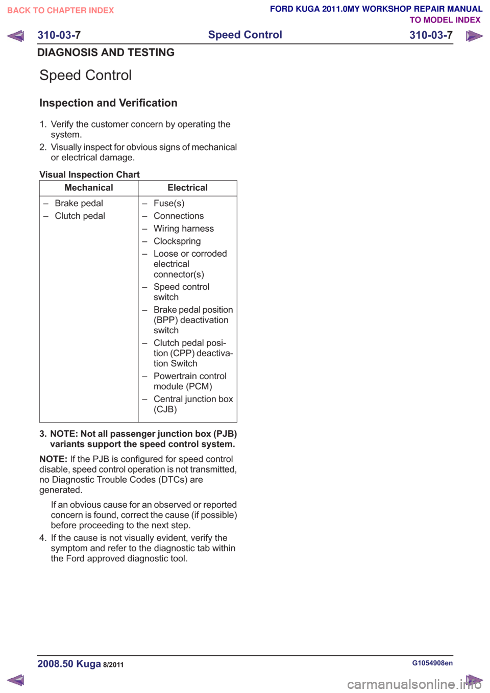
Speed Control
Inspection and Verification
1. Verify the customer concern by operating thesystem.
2. Visually inspect for obvious signs of mechanical or electrical damage.
Visual Inspection Chart
Electrical
Mechanical
– Fuse(s)
– Connections
– Wiring harness
– Clockspring
– Loose or corrodedelectrical
connector(s)
– Speed control switch
– Brake pedal position (BPP) deactivation
switch
– Clutch pedal posi- tion (CPP) deactiva-
tion Switch
– Powertrain control module (PCM)
– Central junction box (CJB)
– Brake pedal
– Clutch pedal
3. NOTE: Not all passenger junction box (PJB) variants support the speed control system.
NOTE: If the PJB is configured for speed control
disable, speed control operation is not transmitted,
no Diagnostic Trouble Codes (DTCs) are
generated.
If an obvious cause for an observed or reported
concern is found, correct the cause (if possible)
before proceeding to the next step.
4. If the cause is not visually evident, verify the symptom and refer to the diagnostic tab within
the Ford approved diagnostic tool.
G1054908en2008.50 Kuga8/2011
310-03- 7
Speed Control
310-03- 7
DIAGNOSIS AND TESTING
TO MODEL INDEX
BACK TO CHAPTER INDEX
FORD KUGA 2011.0MY WORKSHOP REPAIR MANUAL
Page 2012 of 2057
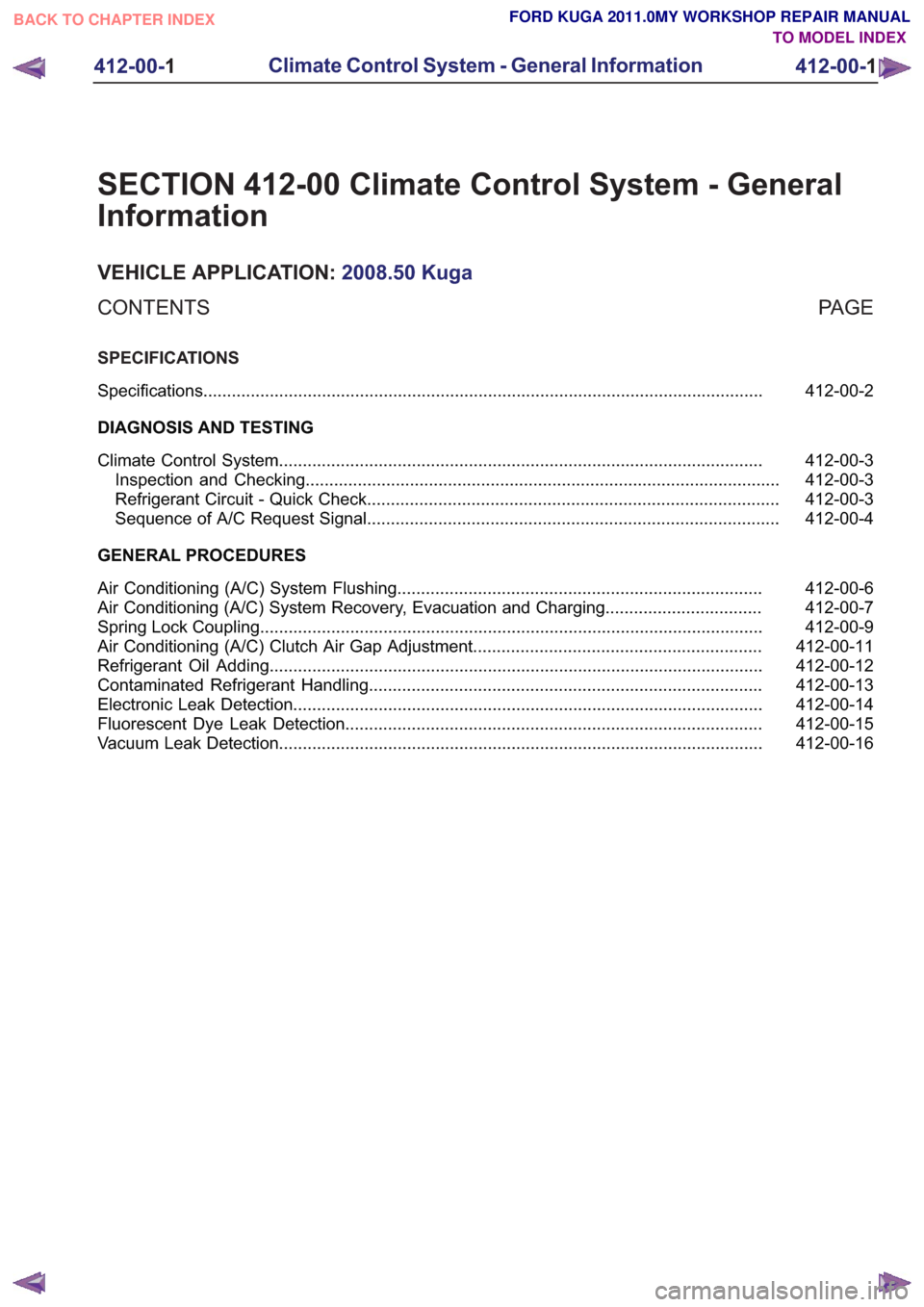
SECTION 412-00 Climate Control System - General
Information
VEHICLE APPLICATION:2008.50 Kuga
PA G E
CONTENTS
SPECIFICATIONS
412-00-2
Specifications ........................................................................\
..............................................
DIAGNOSIS AND TESTING 412-00-3
Climate Control System ........................................................................\
..............................
412-00-3
Inspection and Checking ........................................................................\
............................
412-00-3
Refrigerant Circuit - Quick Check ........................................................................\
...............
412-00-4
Sequence of A/C Request Signal ........................................................................\
...............
GENERAL PROCEDURES 412-00-6
Air Conditioning (A/C) System Flushing ........................................................................\
.....
412-00-7
Air Conditioning (A/C) System Recovery, Evacuation and Charging .................................
412-00-9
Spring Lock Coupling ........................................................................\
..................................
412-00-11
Air Conditioning (A/C) Clutch Air Gap Adjustment .............................................................
412-00-12
Refrigerant Oil Adding ........................................................................\
................................
412-00-13
Contaminated Refrigerant Handling ........................................................................\
...........
412-00-14
Electronic Leak Detection ........................................................................\
...........................
412-00-15
Fluorescent Dye Leak Detection ........................................................................\
................
412-00-16
Vacuum Leak Detection ........................................................................\
..............................
412-00-1
Climate Control System - General Information
412-00- 1
.
TO MODEL INDEX
BACK TO CHAPTER INDEX
FORD KUGA 2011.0MY WORKSHOP REPAIR MANUAL
Page 2013 of 2057
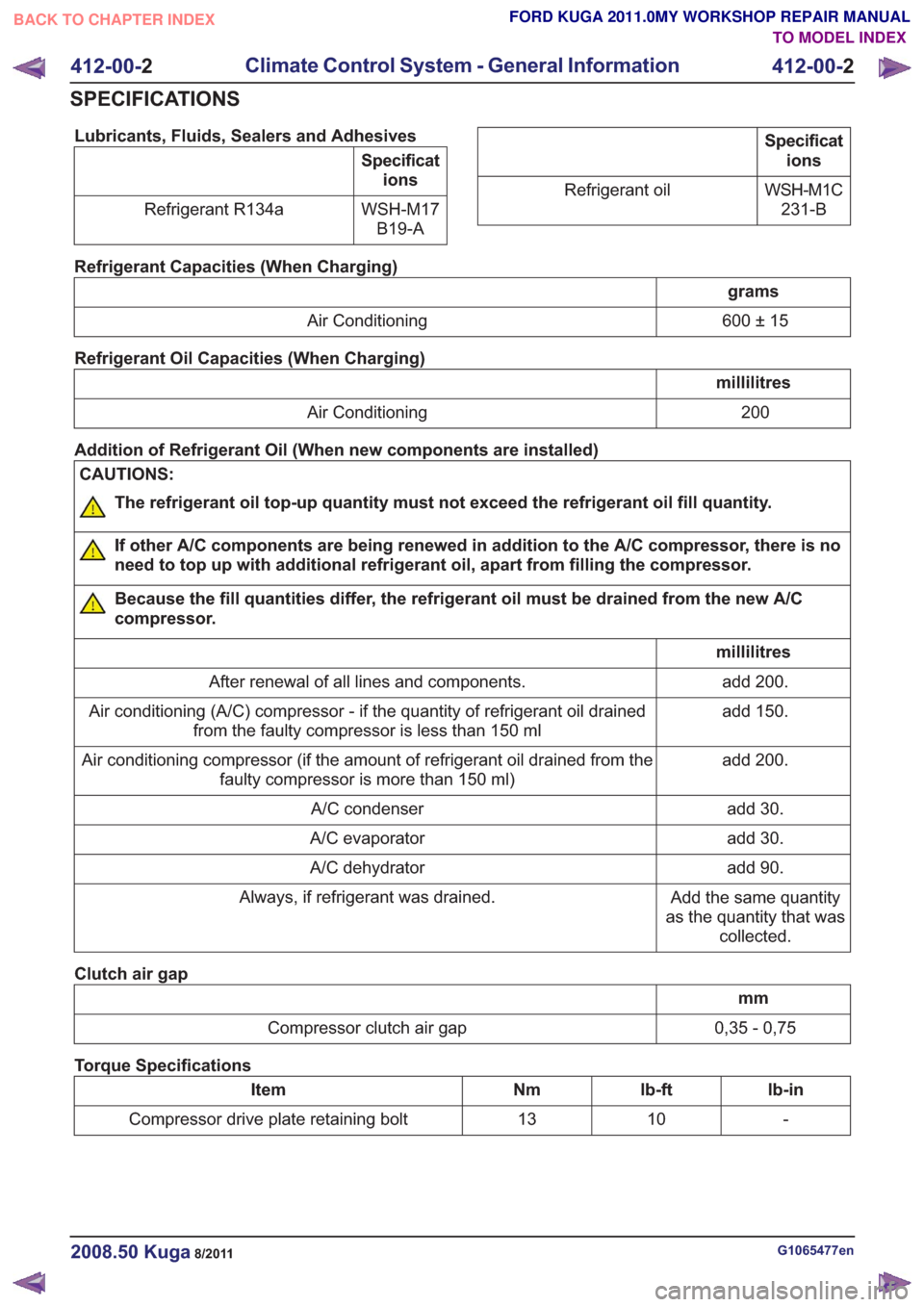
Lubricants, Fluids, Sealers and Adhesives
Specifications
WSH-M17 B19-A
Refrigerant R134a
Specificat
ions
WSH-M1C 231-B
Refrigerant oil
Refrigerant Capacities (When Charging)
grams
600 ± 15
Air Conditioning
Refrigerant Oil Capacities (When Charging)
millilitres 200
Air Conditioning
Addition of Refrigerant Oil (When new components are installed)
CAUTIONS:
The refrigerant oil top-up quantity must not exceed the refrigerant oil fill quantity.
If other A/C components are being renewed in addition to the A/C compressor, there is no
need to top up with additional refrigerant oil, apart from filling the compressor.
Because the fill quantities differ, the refrigerant oil must be drained from the new A/C
compressor.
millilitres add 200.
After renewal of all lines and components.
add 150.
Air conditioning (A/C) compressor - if the quantity of refrigerant oil drained
from the faulty compressor is less than 150 ml
add 200.
Air conditioning compressor (if the amount of refrigerant oil drained from the
faulty compressor is more than 150 ml)
add 30.
A/C condenser
add 30.
A/C evaporator
add 90.
A/C dehydrator
Add the same quantity
as the quantity that was collected.
Always, if refrigerant was drained.
Clutch air gap
mm
0,35 - 0,75
Compressor clutch air gap
Torque Specifications
lb-in
lb-ft
Nm
Item
-
10
13
Compressor drive plate retaining bolt
G1065477en2008.50 Kuga8/2011
412-00- 2
Climate Control System - General Information
412-00- 2
SPECIFICATIONS
TO MODEL INDEX
BACK TO CHAPTER INDEX
FORD KUGA 2011.0MY WORKSHOP REPAIR MANUAL
Page 2015 of 2057
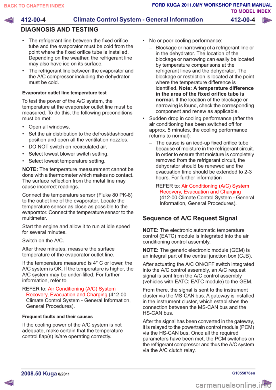
• The refrigerant line between the fixed orificetube and the evaporator must be cold from the
point where the fixed orifice tube is installed.
Depending on the weather, the refrigerant line
may also have ice on its surface.
• The refrigerant line between the evaporator and the A/C compressor including the dehydrator
must be cold.
Evaporator outlet line temperature test
To test the power of the A/C system, the
temperature at the evaporator outlet line must be
measured. To do this, the following preconditions
must be met:
• Open all windows.
• Set the air distribution to the defrost/dashboardposition and open all the ventilation nozzles.
• DO NOT switch on recirculated air.
• Select lowest blower switch setting.
• Select lowest temperature setting.
NOTE: The temperature measurement cannot be
done with a thermometer which makes no contact.
The surface reflection from the metal line may
cause incorrect readings.
Connect the temperature sensor (Fluke 80 PK-8)
to the outlet line of the evaporator. Locate the
temperature sensor as close as possible to the
evaporator. Connect the temperature sensor to the
multimeter.
Start the engine and allow it to run at idle speed
for several minutes.
Switch on the A/C.
After three minutes, measure the surface
temperature of the evaporator outlet line.
If the temperature measured is 4° C or lower, the
A/C system is OK. If the temperature is higher, the
A/C system may be under-filled. For further
information, refer to
REFER to: Air Conditioning (A/C) System
Recovery, Evacuation and Charging (412-00
Climate Control System - General Information,
General Procedures).
Frequent faults and their causes
If the cooling power of the A/C system is not
adequate, make certain that the temperature
control flap(s) is/are operating correctly. • No or poor cooling performance:
– Blockage or narrowing of a refrigerant line orin the dehydrator. The location of the
blockage or narrowing can easily be located
by temperature comparisons at the
refrigerant lines and the dehydrator. The
blockage or restriction is located at the point
where the temperature difference is
identified. Note: A temperature difference
in the area of the fixed orifice tube is
normal. If the location of the blockage or
narrowing is found, check the corresponding
component and renew as applicable.
• Sudden drop in cooling performance (after the air conditioning has been switched off for
approx. 5 minutes, the cooling performance
returns to normal):
– The cause is an iced-up fixed orifice tubebecause of moisture in the refrigerant circuit.
In order to ensure that moisture is completely
removed from the refrigerant circuit, the
dehydrator should be renewed and the
evacuation time should be extended to 2-3
hours. For further information
REFER to: Air Conditioning (A/C) System
Recovery, Evacuation and Charging
(412-00 Climate Control System - General
Information, General Procedures).
Sequence of A/C Request Signal
NOTE: The electronic automatic temperature
control (EATC) module is integrated into the air
conditioning control assembly.
NOTE: The generic electronic module (GEM) is
an integral part of the central junction box (CJB).
After actuating the A/C ON/OFF switch integrated
into the A/C control assembly, an A/C request
signal is sent from the A/C control assembly
(vehicles with EATC: EATC module) to the GEM.
From there, the signal is sent to the instrument
cluster via the MS-CAN bus. A gateway is installed
in the instrument cluster, which establishes the
connection between the MS-CAN bus and the
HS-CAN bus.
After the signal has been converted in the gateway,
it is relayed to the powertrain control module (PCM)
via the HS-CAN bus. Once all the required
parameters have been met, the PCM switches on
the refrigerant compressor and thus the A/C system
via the A/C clutch relay.
G1055878en2008.50 Kuga8/2011
412-00- 4
Climate Control System - General Information
412-00- 4
DIAGNOSIS AND TESTING
TO MODEL INDEX
BACK TO CHAPTER INDEX
FORD KUGA 2011.0MY WORKSHOP REPAIR MANUAL
Page 2022 of 2057
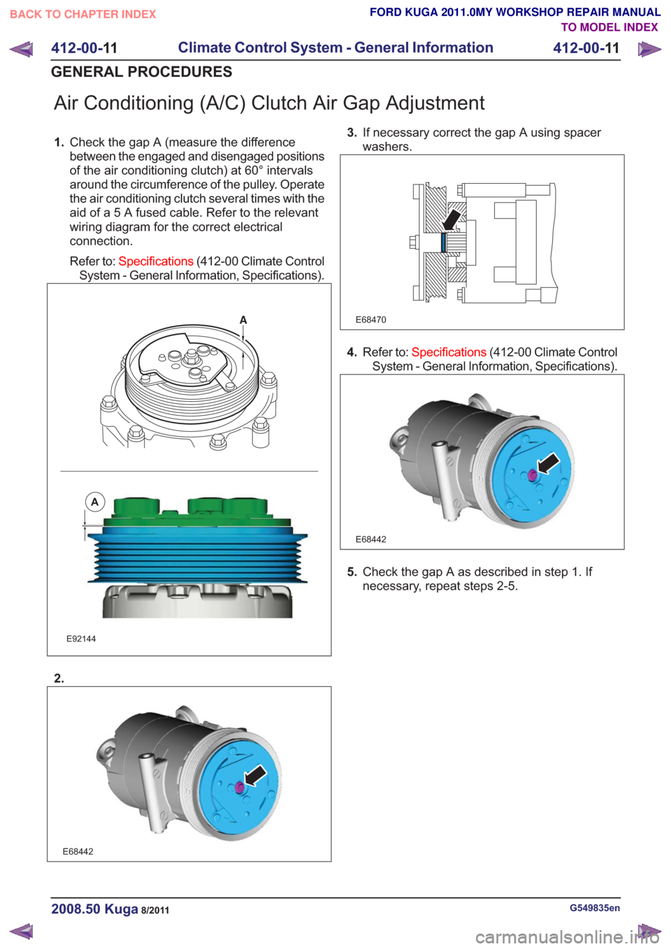
Air Conditioning (A/C) Clutch Air Gap Adjustment
1.Check the gap A (measure the difference
between the engaged and disengaged positions
of the air conditioning clutch) at 60° intervals
around the circumference of the pulley. Operate
the air conditioning clutch several times with the
aid of a 5 A fused cable. Refer to the relevant
wiring diagram for the correct electrical
connection.
Refer to: Specifications (412-00 Climate Control
System - General Information, Specifications).
E92144
A
2.
E68442
3. If necessary correct the gap A using spacer
washers.
E68470
4.Refer to: Specifications (412-00 Climate Control
System - General Information, Specifications).
E68442
5. Check the gap A as described in step 1. If
necessary, repeat steps 2-5.
G549835en2008.50 Kuga8/2011
412-00- 11
Climate Control System - General Information
412-00- 11
GENERAL PROCEDURES
TO MODEL INDEX
BACK TO CHAPTER INDEX
FORD KUGA 2011.0MY WORKSHOP REPAIR MANUAL
Page 2028 of 2057
SECTION 412-01 Climate Control
VEHICLE APPLICATION:2008.50 Kuga
PA G E
CONTENTS
SPECIFICATIONS
412-01-3
Specifications ........................................................................\
..............................................
DESCRIPTION AND OPERATION 412-01-4
Climate Control (Component Location) ........................................................................\
......
412-01-10
Climate Control (Overview) ........................................................................\
........................
412-01-10
Pollen filter ........................................................................\
..................................................
412-01-10
Heat exchanger ........................................................................\
..........................................
412-01-10
Evaporator assembly ........................................................................\
..................................
412-01-10
Blower motor ........................................................................\
..............................................
412-01-11
Fault Memory Interrogation without diagnostics unit - vehicles with automatic temperature
control ........................................................................\
.......................................................
412-01-11
Switch over from Celsius to Fahrenheit ........................................................................\
......
412-01-12
Climate Control (System Operation and Component Description) .....................................
412-01-12
System Diagram ........................................................................\
.........................................
412-01-19
System Operation ........................................................................\
.......................................
412-01-19
Climate control housing ........................................................................\
..........................
412-01-22
Climate control ........................................................................\
........................................
412-01-24
Component Description ........................................................................\
..............................
412-01-24
Air conditioning compressor ........................................................................\
...................
412-01-24
Pollen filter ........................................................................\
..............................................
412-01-24
Control assembly, climate control - vehicles with manual temperature control ..............
412-01-25
Control assembly, climate control - vehicles with automatic temperature control ...........
412-01-25
Control assembly, climate control - vehicles with DVD navigation system with a touch
screen........................................................................\
................................................... 412-01-25
Climate control module - vehicles with DVD navigation system with a touch screen.....
412-01-25
Sun sensor - vehicles with automatic temperature control .............................................
412-01-26
In-vehicle temperature sensor ........................................................................\
................
412-01-26
Ambient temperature sensor ........................................................................\
..................
412-01-26
Blower motor ........................................................................\
...........................................
412-01-26
Blower control module - vehicles equipped with automatic temperature control ............
REMOVAL AND INSTALLATION 412-01-28
(34 626 4)
Air Conditioning (A/C) Compressor — 2.5L Duratec (147kW/200PS) - VI5 ....
412-01-29
Air Conditioning (A/C) Compressor to Condenser Discharge Line .....................................
412-01-30
Air Conditioning (A/C) Compressor to Condenser Discharge Line — 2.5L Duratec
(147kW/200PS) - VI5 ........................................................................\
................................
412-01-31
Condenser ........................................................................\
..................................................
412-01-35
Clutch and Clutch Field Coil........................................................................\
.......................
412-01-36
Pollen Filter — RHD........................................................................\
...................................
412-01-37
(34
374 0)
Blower Motor — RHD ........................................................................\
.............
412-01-40
(34 382 0)
Blower Motor Resistor — Vehicles With: Manual Temperature Control, RHD .
412-01-41
(34 382 0)
Blower Motor Resistor — Vehicles With: Dual Automatic Temperature
Control ........................................................................\
..................................
412-01- 1
Climate Control
412-01- 1
.
TO MODEL INDEX
BACK TO CHAPTER INDEX
PAGE 1 OF 2 FORD KUGA 2011.0MY WORKSHOP REPAIR MANUAL
Page 2045 of 2057
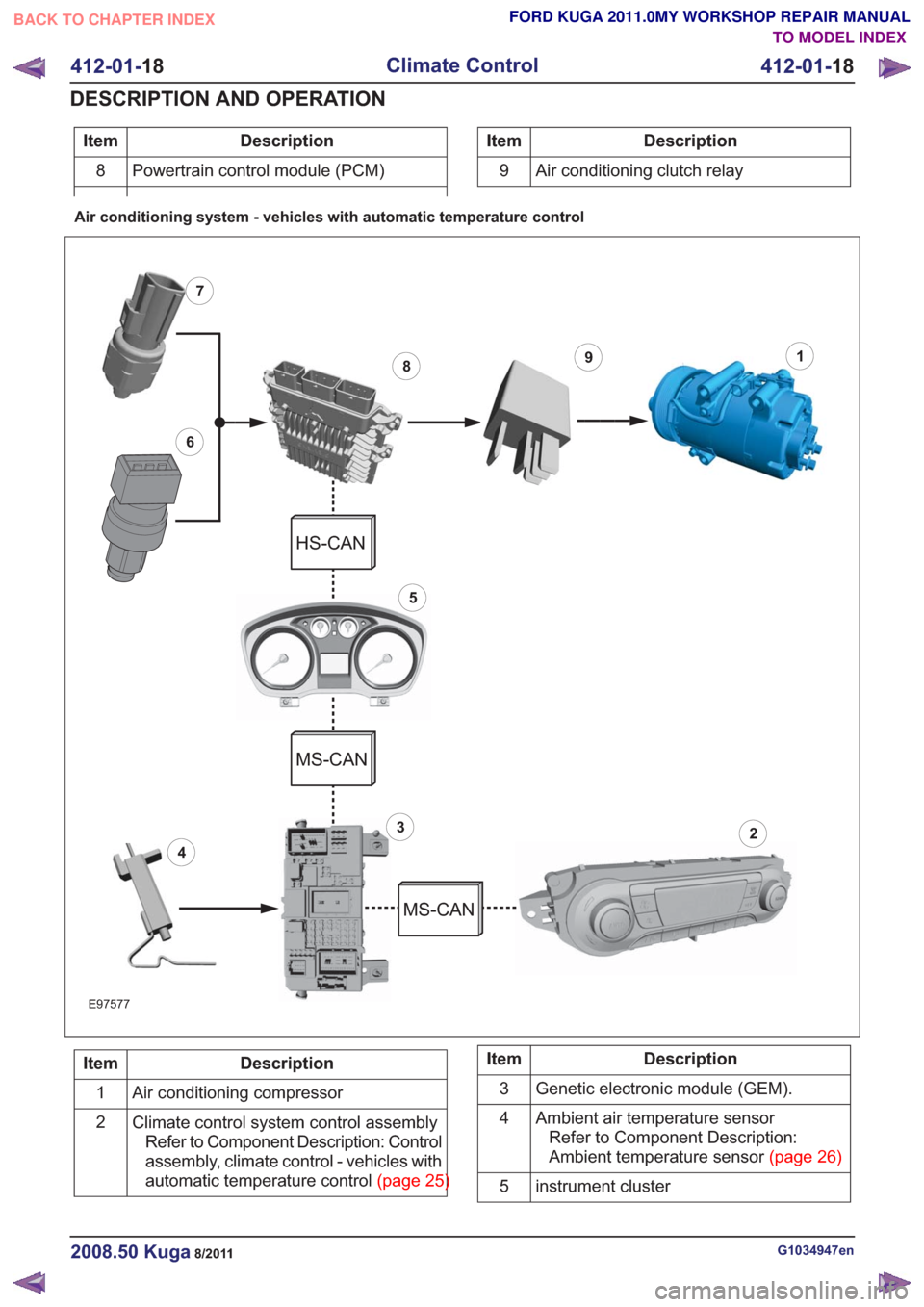
Description
Item
Powertrain control module (PCM)
8Description
Item
9 Air conditioning clutch relay
Air conditioning system - vehicles with automatic temperature control
18
6
7
3
9
5
2
4
E97577
HS-CAN
MS-CAN
MS-CAN
Description
Item
Air conditioning compressor
1
Climate control system control assemblyRefer to Component Description: Control
assembly, climate control - vehicles with
automatictemperaturecontrol(page25)
2Description
Item
Genetic electronic module (GEM).
3
Ambient air temperature sensorRefer to Component Description:
Ambienttemperaturesensor(page26)
4
instrument cluster
5
G1034947en2008.50 Kuga8/2011
412-01- 18
Climate Control
412-01- 18
DESCRIPTION AND OPERATION
TO MODEL INDEX
BACK TO CHAPTER INDEX
FORD KUGA 2011.0MY WORKSHOP REPAIR MANUAL
Page 2046 of 2057
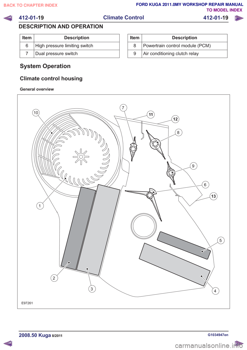
Description
Item
High pressure limiting switch
6
Dual pressure switch
7Description
Item
Powertrain control module (PCM)
8
Air conditioning clutch relay
9
System Operation
Climate control housing
General overview
13
12
11
8
7
9
6
4
5
2
3
E97261
1
10
G1034947en2008.50 Kuga8/2011
412-01- 19
Climate Control
412-01- 19
DESCRIPTION AND OPERATION
TO MODEL INDEX
BACK TO CHAPTER INDEX
FORD KUGA 2011.0MY WORKSHOP REPAIR MANUAL