Page 1880 of 2057

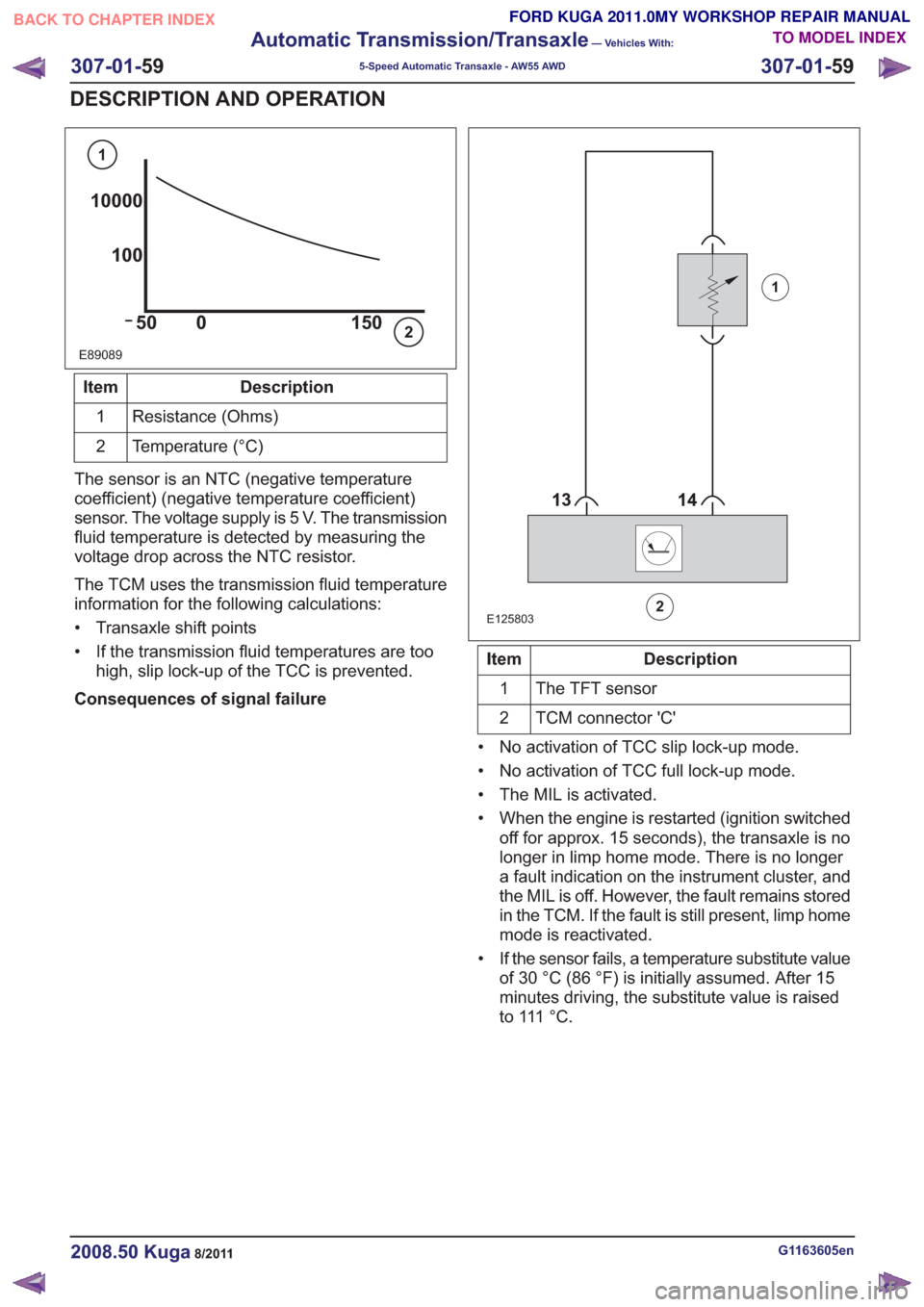
E89089
10000100
50 0 150
1
2
Description
Item
Resistance (Ohms)
1
Temperature (°C)
2
The sensor is an NTC (negative temperature
coefficient) (negative temperature coefficient)
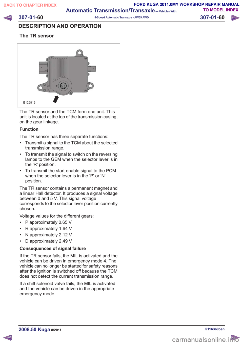
sensor. The voltage supply is 5 V. The transmission
fluid temperature is detected by measuring the
voltage drop across the NTC resistor.
The TCM uses the transmission fluid temperature
information for the following calculations:
• Transaxle shift points
• If the transmission fluid temperatures are too high, slip lock-up of the TCC is prevented.
Consequences of signal failure
88
E125803
1
2
Description
Item
The TFT sensor
1
TCM connector 'C'
2
• No activation of TCC slip lock-up mode.
• No activation of TCC full lock-up mode.
• The MIL is activated.
• When the engine is restarted (ignition switched off for approx. 15 seconds), the transaxle is no
longer in limp home mode. There is no longer
a fault indication on the instrument cluster, and
the MIL is off. However, the fault remains stored
in the TCM. If the fault is still present, limp home
mode is reactivated.
• If the sensor fails, a temperature substitute value of 30 °C (86 °F) is initially assumed. After 15
minutes driving, the substitute value is raised
t o 111 ° C .
G1163605en2008.50 Kuga8/2011
307-01- 59
Automatic Transmission/Transaxle
— Vehicles With:
5-Speed Automatic Transaxle - AW55 AWD
307-01- 59
DESCRIPTION AND OPERATION
TO MODEL INDEX
BACK TO CHAPTER INDEX
FORD KUGA 2011.0MY WORKSHOP REPAIR MANUAL
Page 1881 of 2057

The TR sensor
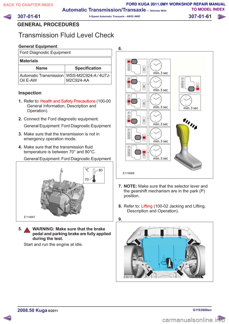
E125819
The TR sensor and the TCM form one unit. This
unit is located at the top of the transmission casing,
on the gear linkage.
Function
The TR sensor has three separate functions:
• Transmit a signal to the TCM about the selectedtransmission range.
• To transmit the signal to switch on the reversing lamps to the GEM when the selector lever is in
the 'R' position.
• To transmit the start enable signal to the PCM when the selector lever is in the 'P' or 'N'
position.
The TR sensor contains a permanent magnet and
a linear Hall detector. It produces a signal voltage
between 0 and 5 V. This signal voltage
corresponds to the selector lever position currently
chosen.
Voltage values for the different gears:
• P approximately 0.65 V
• R approximately 1.64 V
• N approximately 2.12 V
• D approximately 2.49 V
Consequences of signal failure
If the TR sensor fails, the MIL is activated and the
vehicle can be driven in emergency mode 4. The
vehicle can no longer be started for safety reasons
after the ignition is switched off because the TCM
does not detect the current transmission range.
If a shift solenoid valve fails, the MIL is activated
and the vehicle can be driven in the appropriate
emergency mode.
G1163605en2008.50 Kuga8/2011
307-01- 60
Automatic Transmission/Transaxle
— Vehicles With:
5-Speed Automatic Transaxle - AW55 AWD
307-01- 60
DESCRIPTION AND OPERATION
TO MODEL INDEX
BACK TO CHAPTER INDEX
FORD KUGA 2011.0MY WORKSHOP REPAIR MANUAL
Page 1882 of 2057

Transmission Fluid Level Check
General EquipmentFord Diagnostic Equipment
Materials
Specification
Name
WSS-M2C924-A / 4U7J-
M2C924-AA
Automatic Transmission
Oil E-AW
Inspection
1.
Refer to: Health and Safety Precautions (100-00
General Information, Description and
Operation).
2. Connect the Ford diagnostic equipment.
General Equipment: Ford Diagnostic Equipment
3. Make sure that the transmission is not in
emergency operation mode.
4. Make sure that the transmission fluid
temperature is between 70° and 80°C.
General Equipment: Ford Diagnostic Equipment
80
70
E114667
5. WARNING: Make sure that the brake pedal and parking brake are fully applied
during the test.
Start and run the engine at idle. 6.
E114668
7. NOTE:
Make sure that the selector lever and
the gearshift mechanism are in the park (P)
position.
8. Refer to: Lifting(100-02 Jacking and Lifting,
Description and Operation).
9.
E98183
G1163606en2008.50 Kuga8/2011
307-01- 61
Automatic Transmission/Transaxle
— Vehicles With:
5-Speed Automatic Transaxle - AW55 AWD
307-01- 61
GENERAL PROCEDURES
TO MODEL INDEX
BACK TO CHAPTER INDEX
FORD KUGA 2011.0MY WORKSHOP REPAIR MANUAL
Page 1883 of 2057
10.
E114670
11. CAUTION: Use lint free cloth.
E114671
80
70
12. Adjust the fluid level in the automatic
transmission if necessary.
Material: Automatic Transmission Oil E-AW
(WSS-M2C924-A / 4U7J-M2C924-AA)
transmission fluid
E114672
13.
E114938
14.
E98183
15. Switch off the engine.
16. Disconnect the Ford diagnostic equipment.
General Equipment: Ford Diagnostic Equipment
G1163606en2008.50 Kuga8/2011
307-01- 62
Automatic Transmission/Transaxle
— Vehicles With:
5-Speed Automatic Transaxle - AW55 AWD
307-01- 62
GENERAL PROCEDURES
TO MODEL INDEX
BACK TO CHAPTER INDEX
FORD KUGA 2011.0MY WORKSHOP REPAIR MANUAL
Page 1884 of 2057
Transmission Fluid Drain and Refill
General EquipmentFluid Container
Materials
Specification
Name
WSS-M2C924-A / 4U7J-
M2C924-AA
Automatic Transmission
Oil E-AW
Draining
17.
Refer to: Health and Safety Precautions (100-00
General Information, Description and
Operation).
18. Refer to: Lifting(100-02 Jacking and Lifting,
Description and Operation).
19.
E98183
20. WARNING: Be prepared to collect escaping fluid.
General Equipment: Fluid Container
E114758
21.Torque: 40Nm
E114758
Filling
22.
E114670
23.Use a suitable plastic tube.
E114933
G1163607en2008.50 Kuga8/2011
307-01- 63
Automatic Transmission/Transaxle
— Vehicles With:
5-Speed Automatic Transaxle - AW55 AWD
307-01- 63
GENERAL PROCEDURES
TO MODEL INDEX
BACK TO CHAPTER INDEX
FORD KUGA 2011.0MY WORKSHOP REPAIR MANUAL
Page 1885 of 2057
24. CAUTION: Make sure that all openingsare sealed.
E114759
25.
E114760
26. CAUTION: Take extra care not todamage the seal.
Use a suitable clear plastic tube.
General Equipment: Fluid Container
E114761
27.Material: Automatic Transmission Oil E-AW
(WSS-M2C924-A / 4U7J-M2C924-AA)
transmission fluid
E114762
2l
28. N O T E : Make sure that the selector lever and
the gearshift mechanism are in the park (P)
position.
29. Start and run the engine at idle.
30. Switch off the engine, if bubbles are visible in
the clear plastic tube.
E114807
G1163607en2008.50 Kuga8/2011
307-01- 64
Automatic Transmission/Transaxle
— Vehicles With:
5-Speed Automatic Transaxle - AW55 AWD
307-01- 64
GENERAL PROCEDURES
TO MODEL INDEX
BACK TO CHAPTER INDEX
FORD KUGA 2011.0MY WORKSHOP REPAIR MANUAL
Page 1890 of 2057
Main Control Valve Body
Removal
1.Refer to: Transmission Fluid Pan (307-01
Automatic Transmission/Transaxle - Vehicles
With: 5-Speed Automatic Transaxle - AW55
AWD, Removal and Installation).
2. NOTE: Note the position of the electrical
connectors.
E115690
3. CAUTION: Make sure that no component falls off during removal.
NOTE: Note the different lengths of the bolts.
E115691
x2
4.
E115692
G1163642en2008.50 Kuga8/2011
307-01- 69
Automatic Transmission/Transaxle
— Vehicles With:
5-Speed Automatic Transaxle - AW55 AWD
307-01- 69
REMOVAL AND INSTALLATION
TO MODEL INDEX
BACK TO CHAPTER INDEX
FORD KUGA 2011.0MY WORKSHOP REPAIR MANUAL
Page 1894 of 2057
Torque Converter Seal
Special Tool(s) / General Equipment303-293
Remover, Crankshaft Seal
21143
Special Tool(s) / General Equipment308-095
Installer, Input Shaft Bearing
16038
Round-Ended Steel Rule
Materials
Specification
Name
WSS-M2C924-A / 4U7J-
M2C924-AA
Automatic Transmission
Oil E-AW
Removal
1.
Refer to: Transmission (307-01 Automatic
Transmission/Transaxle - Vehicles With:
5-Speed Automatic Transaxle - AW55 AWD,
Removal).
2.
E115423
3. Special Tool(s): 303-293
303-293303-293
E115424
G1163637en2008.50 Kuga8/2011
307-01- 73
Automatic Transmission/Transaxle
— Vehicles With:
5-Speed Automatic Transaxle - AW55 AWD
307-01- 73
REMOVAL AND INSTALLATION
TO MODEL INDEX
BACK TO CHAPTER INDEX
FORD KUGA 2011.0MY WORKSHOP REPAIR MANUAL